
 ?Mathematical formulae have been encoded as MathML and are displayed in this HTML version using MathJax in order to improve their display. Uncheck the box to turn MathJax off. This feature requires Javascript. Click on a formula to zoom.
Abstract
Water mists are an effective means of suppressing coal fires in enclosed spaces. In the present work, A new type of nitrogen-water mist atomizer was developed. This atomizing device does not need additional power facilities. Only relying on the interaction between nitrogen generated by nitrogen injection equipment in coal mine and water in underground pipelines, it can produce nitrogen with large flow rate, small droplet size, uniform particle size distribution and sufficient mixing, and water vapor liquid two-phase fluid. The structure and working principle of water atomization device were investigated. Numerical simulations and experimentation using the five-hole probe method were used to assess the velocity distributions generated by the atomization device when employing different starter twist numbers CL, and the optimal number was found. With the increase of CL, the gas rotating jet field in the expansion section tends to be more uniform and stable, and the backflow area of the rotating jet appears earlier. At the same time, the tangential velocity conducive to the liquid atomization process also increases significantly. A fire extinguishing experiment in an enclosed space demonstrated that the water mist produced a significant cooling effect and could reduce the combustion temperature effectively.
1. Introduction
Coal fires are a major hazard associated with coal production, and often lead to injury and significant property loss (Liu Citation2009; Guo et al. Citation2018; Banerjee Citation1985; Xu Citation2006; Wu and Liu Citation2011). The high temperature and harmful smoke products produced in the fire pose a great threat to the safety of underground workers. And they may cause gas and coal dust explosion. To prevent underground fires, direct fire extinguishing techniques such as the excavation of fire sources, water injection, grouting, inert gas injection, foam injection (including two-phase foam and three-phase foam), and gel injection are commonly used (Tian Citation2009; Shi et al. Citation2017; Guo and Ren Citation2019; Liang Citation2010; Lu et al. Citation2018; Singh and Tripathi Citation1996; Zheng Citation2014;Walter Citation1981). However, if the fire in a goaf is out of control, the working face must be closed. In recent years, India's Central Mining Research Institute (CMRI) has listed water mist technology, liquid nitrogen and high stability nitrogen foam as three major technical means to prevent and control coal mine fire, and carried out a series of experimental studies using simulated roadway. They believe that one of the first advantages of water mist is that it can put out fires without sealing off the fire area. In addition, the water mist can reduce the degree of smoke flow reversal. Through experimental research, it is also found that water mist can reduce the intensity of underground fire, reduce the production of combustion products and the number of suspended particles, and the following experimental conclusions are drawn (Ray and Singh Citation2005; Ray and Singh Citation2007): After 20 minutes of water mist spraying, the temperature in the simulated roadway decreased to a large extent, and its average drop value reached 294 °C/h, and the phenomenon of smoke flow backsliding was greatly reduced. After the application of fine water mist, the oxygen concentration in the fire area increased to 19%, while the smoke produced by simultaneous combustion decreased significantly, which indicated that the fine water mist prevented the fire development process. Water mist reduced the generation rate of CO2 and CO by 89% and 93% respectively. In the fire extinguishing experiment of water mist, it was found that the hydrogen concentration increased by 0.01-0.26%, which would not reach the explosion limit, and the use of water mist would not cause water gas explosion. Fine mist reduces the opacity of smoke by 84% and improves visibility. Malcolm j. McPherson believes that water mist technology is an effective way to control the development of fire. When water mist is heated, a large amount of water vapor can replace the oxygen that helps combustion, and separate the fuel from the accelerant. Nitrogen-water mists have been found to be an effective technique to reduce the temperature of a closed fire zone, thus shortening the closing time while avoiding re-ignition after unsealing (NFPA, 2006; Wang et al. Citation2016; Grant et al. Citation2000; Kong et al. Citation2018).
For such a complex and diverse space in underground coal mine, the application of water mist technology will encounter difficulties: at the present stage, high pressure atomization mode is generally adopted in the water mist generating device for fire suppression. Second, the diameter of atomizing nozzle is very small, generally about 1 mm, it is difficult to ensure the flow of water under the premise of ensuring that the nozzle is not blocked; Third, the traditional distributed nozzle fire extinguishing system is obviously not suitable for the shaft and roadway where the space structure changes frequently. Therefore, it is necessary to study the fine water mist fire extinguishing technology which is suitable for the actual environmental characteristics of underground coal mine(Tang et al. Citation2019).
The structure of the atomization device directly affects the fire-prevention effect of the water mist. Currently, the methods for atomizing liquids primarily include impact, high pressure, static electricity, and ultrasonic waves. The impact and high-pressure methods tend to produce unstable atomization, such that the atomized particles are unevenly distributed, the energy consumption is significant, and pressurized equipment is needed. In addition, wastewater is often employed, which contains impurities such as coal and rock particles. These can easily block the tiny channels of the nozzle, thus reducing the flow area and atomization flow. Very small, uniform droplets can be obtained using ultrasonic or electrostatic waves, but the diameters of such droplets can be as low as several nanometers, which is not suitable for fire prevention. Moreover, the mist production rate is low, and so these devices are generally only used for laboratory and medical purposes rather than in industry, especially in underground coal mines (Zhong et al. Citation2016; Jones and Nolan Citation1995; Guo et al. Citation2013; Fan Citation2011). There are several rotational methods. These include the tangential injection method (Yu et al. Citation2016), in which the most common technology is a spin-up mode cyclone separator, but there is air column in atomization field, which is not conducive to fire prevention. Another approach is the inner pipe diversion method (Liu and Zhang Citation2006), which generates a swirling jet flow by installing an inclined blade to guide flow in the nozzle. This structure accelerates the atomization of the liquid by means of the momentum generated by the rotation of the air, although the structure and working conditions need to be optimized. Lastly, there is the mechanical rotation method (Dunand et al. Citation2005), in which weak rotation occurs in a long rotating tube and strong rotation is imparted by an inner rotary plate, such that the flow field is much more complicated. The mechanical rotation method requires a power supply, which increases the difficulty and hazards of this process, especially in environments involving explosive gas or dust, such as in a coal mine. It is therefore evident that it would be beneficial to develop a novel atomization device that takes full advantage of the cooling properties of water mists. A direct injection nozzle has a simple structure but poor atomization performance, and is not suitable for high flow conditions. In contrast, a centrifugal nozzle imparts a better atomization effect, but contains moving internal parts and requires an external force to maintain stable rotation, and so consumes large amounts of energy. A dual-channel gas-flow atomizing nozzle has the advantages of small droplet size and a simple structure, but the particle size in the water mist it produces is less than 100 microns, which is not suitable for downhole solid fire control (Zhuang et al. Citation2017; Qi Citation2017).
So we developed is suitable for the coal mine actual application of new nitrogen-water mist device, the device will be able to rely on underground roadway water nitrogen injection system provides the nitrogen and the interaction between aerosol mixing, spread good performance of the large flow rate of nitrogen - water mist, and does not need to add additional power facilities; The experimental system of nitrogen-water mist was constructed, and the atomization principle and performance of nitrogen-water mist, diffusion performance in confined space and fire-extinguishing ability were analyzed by combining basic theory and numerical simulation method. An analysis of the structures and working principles of such atomization devices suggests that the starter twist number (the number of turns in the starter element within the atomization device) is the key factor affecting the swirling intensity. In the present work, numerical simulations and the five-hole probe experimental method were used to investigate the velocity distribution in an atomization device with different starter twist numbers, and the optimal number was found to be three. The particle size distributions of water mists produced by the device were studied under different working conditions. As well, fire extinguishing experiments in an enclosed space demonstrated that the resulting water mists imparted a significant cooling effect and effectively reduced combustion temperatures.
2. Design of the water atomization device
2.1. Structure and working mechanism
provides a diagram of the water atomization device, which consists of a Venturi tube, starter, and water injector. The starter is fixed in the nozzle, while the water injector (which contains holes) is connected to the Venturi tube throat. When used in underground coal mines, the compressed nitrogen inlet and water inlet are connected to nitrogen and water supply pipes, respectively. In this device, compressed nitrogen through the starter into the nozzle of the Venturi tube and develops into a high speed swirling jet. Simultaneously, water is injected into the throat through the water injector. This water collides with the nitrogen swirling jet to generate a uniform water mist in the gas-liquid mixing chamber.
Figure 1. Structure of atomization device.
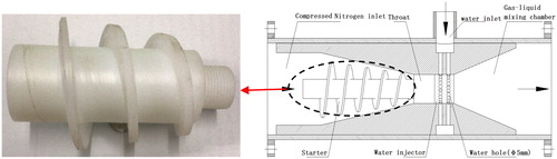
Compressed nitrogen performs two roles in the formation of the water mist. Firstly, it provides axial and tangential kinetic energy for the formation of the water mist. Secondly, it supplies energy that drives mixing of the nitrogen and water to prevent water from sinking to the bottom of the atomization device (Zhong et al. Citation2016).
2.2. Swirling intensity in the starter
The geometrical structure of the starter determines the characteristics of the swirling jet, especially the swirling intensity. This is a non-dimensional value, expressed as the ratio of the rotational momentum moment flux to the axial momentum flux (Cen and Fan Citation1990), as in the Equationequation (1)(1)
(1)
(1)
(1)
where S is the swirling intensity, M is the tangential momentum flux (kg.m2.s−1), K is the axial momentum flux (kg·m.s−1), and D is the swirling diameter (m).
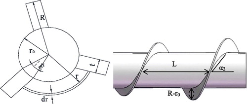
provides a diagram of the geometry of the impeller outlet. Here, the relationship between the various dimensions is
(2)
(2)
Figure 2. Sectional and side view of the starter.
Hence, we can write
(3)
(3)
and
(4)
(4)
The micro area of the flow at any radius, r, is given by
(5)
(5)
At the outlet of the blade, the axial momentum of the fluid micro area is
(6)
(6)
and the tangential momentum moment of the fluid microelement is
(7)
(7)
The fluid tangential momentum moment, M, and axial momentum, K, at the outlet are
(8)
(8)
and
(9)
(9)
Because the swirling jet is generated in the pipeline, where space is limited, compared to the axial and tangential speeds, the radial velocity is small enough to be negligible in calculations, such that
(10)
(10)
Combining EquationEqs. (8)(8)
(8) to (Equation10
(10)
(10) ) with EquationEq. (1)
(1)
(1) , gives
(11)
(11)
assuming that
(12)
(12)
The swirling force of the internal swirling jet in the atomization device is
(13)
(13)
such that
(14)
(14)
In the above equations, L is the total length of the starter (m), t is the thickness of the blade (m), R is the radius of the impeller (m), CL is the starter twist number, r0 is the radius of the hub (m), α2 is the exit angle of the blade(°), Ck is the number of blades in the starter, A is the micro area of the flow(m2), ρ is the water density (g/mL), w is the tangential velocity (m/s), u is the radial velocity (m/s) and C is the velocity of the swirling jet (m/s).
To reduce the loss of the energy of the nitrogen, Ck is given a value of 1. Thus, based on the geometric structure of the atomization device, the swirling intensity, S, is related solely to the starter twist number, CL.
3. Numerical simulation of flow field characteristics
According to the working principle of the atomization device, compressed nitrogen forms a rotating jet after passing through the starter and the throat, and its velocity can be decomposed into an axial velocity, u, a radial velocity, v, and a tangential velocity, w. In this device, the water droplets are twisted as they are atomized under the effect of the three-dimensional velocity. Therefore, if the gas flow rate and the initial velocity are constant, the primary factor affecting the strength of the rotating jet in the atomization device is CL.
This work simulated the flow field characteristics of the rotating gas jets in the atomization device, and analyzed the distribution of the three-dimensional velocity field of the rotating jets formed with varying helical turns. The particle size distributions in the mists generated by devices with different structures were investigated through experimentation and the optimal number of spinner blades was determined.
3.1. Physical model
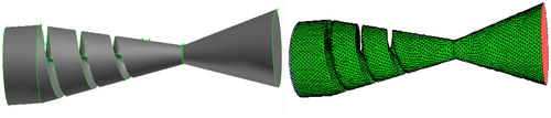
The initial blade number was one and the CL values were 1, 2, 3 or 4. The GAMBIT software package was utilized to construct a solid geometric model, with its origin at the center of the outlet face. Subsequently, the TGrid program was used to automatically generate computational meshes comprising cells with a triangular tetrahedral node structure. shows the physical model and the mesh generation of a device for which Ck = 1 and CL = 3.
Figure 3. Physical model and mesh generation of the device.
The entrance of the simulated area was positioned in the spinning-section, and the Reynolds Stress Model(RSM)turbulence model in the Fluent software package was employed to numerically simulate the three-dimensional flow field of the atomization device. The RSM gives up the Boussinesq hypothesis of isotropy, includes more physical processes, takes into account the effect of turbulent anisotropy, and has higher prediction accuracy for complex flows. The RSM are closer to the experimental data than with the Standard k-X model (Zhang and Liu Citation2005). It is very suitable for simulating complex flow fields such as hydrocyclones with high-speed rotating flow because the sharp changes of stress tensor caused by fluid rotation or streamline bending are fully considered (Wang and Chen Citation2006; Liang et al. Citation2007; Li and Qiu Citation2008).
In this simulation, the boundary conditions are set as follows:
Meshing: The model contained 9669 nodes, 4524 mixed wall faces, 99,668 mixed interior faces and 50,965 cells.
Inlet boundary conditions:It is considered that the gas turbulence has been fully developed, and the normal velocity of the inlet section is the mean value, that is, the velocity is set as 10 m s.
Outlet boundary conditions:An outflow setting for the outlet.
Wall condition: No slippage solid wall condition is adopted for flow boundary.
The boundary conditions included an inlet velocity of 10 m/s, an outflow setting for the outlet, and a fixed wall setting for all other surfaces of the device. The model contained 9669 nodes, 4524 mixed wall faces, 99,668 mixed interior faces and 50,965 cells. The swirling intensity is an important characteristic of the swirling jet, and reflects the degree of gas rotation. At the same position in the three-dimensional velocity field, a greater swirling intensity is correlated with a lower axial velocity and higher radial and tangential velocities. Based on the structure of the atomization device, the most important factors affecting the rotating gas flow field are the number of blades and the starter twist number. Therefore, varying the number of air intakes and helices, while maintaining the same working conditions, allowed an analysis of the rotating gas flow field in the expansion section. These effects were analyzed to achieve a better atomizing effect.
3.2. Effect of CL on velocity distribution
3.2.1. Axial velocity distribution
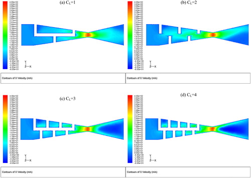
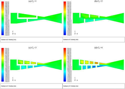
shows the axial velocity distribution contour of the nitrogen flow at CL = 1, 2, 3 and 4. The swirling jet exhibits backflow in all four atomization devices. As an example, when CL = 1, a weak backflow occurs at the outlet of the Venturi tube, while, at CL = 2, the backflow occurs earlier but the flow field distribution is uneven and unstable. When CL = 3 and 4, the backflow zone is closer to the throat and the intensity is much stronger. In addition, the flow field distribution is more uniform and stable, which provides adequate time for mixing and atomizing.
Figure 4. Contour of axial velocity.
3.2.2. Tangential velocity distribution
shows the tangential velocity distribution contour of the nitrogen flow for CL = 1, 2, 3 and 4. Liquid atomization is mainly divided into three types: bag-shaped fragmentation, shear fragmentation and explosive fragmentation. The liquid atomization process in the nitrogen-water mist atomizing device is completed by the water flow twisting, deforming and splitting under the action of airflow shear, and at the same time under the action of turbulence velocity and pressure changes. Water flow first expands into a twisted thin layer under the action of tangential shear airflow, and then divides into finer droplets to form water mist. Therefore, the tangential velocity of the rotating airflow plays a particularly important role in the atomization process. A swirling jet is formed as the nitrogen flows through the starter and the intensity in the throat is strong. The tangential velocity increases significantly as the starter twist number is increased, which improves the mixing intensity and imparts a better atomizing effect.
Figure 5. Contour of tangential velocity.
3.2.3. Radial velocity distribution
shows the radial velocity distribution contours of the nitrogen flow for CL values of 1, 2, 3 and 4. CL = 3,4 radial velocity is more symmetrical, mainly because the rotation formed by the gas is more stable after passing through more twist number, so it presents better symmetry in space. The greater the turbulence intensity of the rotary gas jet flow field is, the stronger its mixing and entrainment ability. Meanwhile, better symmetry of flow field can improve the accuracy and stability of atomizing device. The radial velocity is also an order of magnitude smaller than the axial and tangential velocities of the swirling jet, suggesting that the starter twist number has little effect on the radial velocity. This result is consistent with EquationEq. (10)(10)
(10) .
Figure 6. Contour of radial velocity.
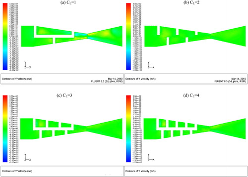
In summary, the simulation results demonstrate that, when CL = 1 or 2, the swirling intensity is too weak to atomize water. In contrast, CL values of 3 or 4 provide stronger backflow, a more complete mixing process, and a better atomization effect.
3.3. Velocity distribution at the cross-section centerline when CL = 3 or 4
To determine the final starter twist number, an experiment was conducted to verify the velocity distribution, employing a five-hole probe method.
The corresponding speeds at each measurement points were calculated using the equation
(15)
(15)
where: p0: total pressure, (Pa); ps: static pressure, (Pa); ρa: air intensity, g/ml.
velocity of fluid, (m/s).
The CL values were determined by comparing the experimental and simulation results.
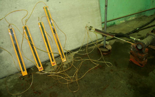
3.3.1. Experimental process
In these trials, an atomization device with CL = 3 was initially tested in conjunction with the equipment shown in . Prior to each trial, a differential manometer was fixed in place, its angle relative to the horizontal was determined, and it was connected to the five-hole probe. The nitrogen compressor was started and the nitrogen flow was set to 200 m3/h with a water flow of 2 m3/h. The variations in pressure were monitored until the liquid surfaces in the manometer reached the same level, at which point the pressure value was recorded. The above process was then repeated to assess the pressure at the second measurement point, after which the atomization device with CL = 4 was substituted and the entire process was repeated.
Figure 7. Five-hole probe.
3.3.2. Results comparison
3.3.2.1. Axial velocity
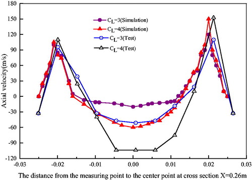
As shown in , the axial velocity in the cross-section area for which x = 0.26 m exhibits a central low-speed area, and the minimum velocity first decreases and then increases. The overall axial velocity distribution initially has an ‘M’ shape that gradually develops into a saddle shape. The maximum is near the center point of 0.02 m and the efflux velocity becomes smaller due to the boundary layer effect at the edge of the atomization device. When CL = 3, the center area is increased in size, such that the velocity curve becomes flat and even.
Figure 8. Axial velocity distribution.
3.3.2.2. Tangential velocity
The tangential velocity distribution of the swirling jet presents an inclined ‘N’ shape, and the axial center of the section is symmetrical. The maximum tangential velocity of the swirling jet appears at a point 0.02 m from the center point of the interface. As the capacity of the atomizing device to absorb the surrounding nitrogen increases, the width of the boundary layer of the rotating jet becomes larger. Compared with the axial velocity, the tangential velocity of the swirling jet weakens more rapidly in the axial direction, indicating that the mixing effect of the swirling jet primarily results from the tangential velocity. Therefore, increasing the swirling intensity requires an increase in the tangential velocity ().
Figure 9. Tangential velocity distribution.
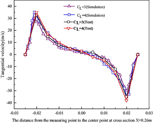
Figure 10. Radial velocity distribution.
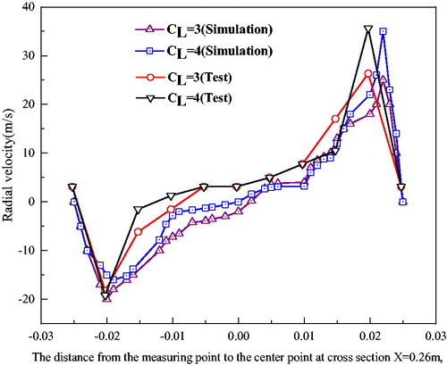
3.3.2.3. Radial velocity
As shown in , the radial velocity distribution has an ‘S’ shape and decays rapidly along the vertical axis. The maximum value of the radial velocity initially appears some distance from the center of the jet flow. As the distance from the center point decreases, the maximum value gradually approaches that of the center of the swirling jet.
The three-dimensional velocity distribution along the cross-section centerline (where x = 0.26 m) of the atomization device indicates that the distributions of the radial and tangential velocities are similar, whereas the axial velocity profile is different. In addition, the axial velocity at CL = 3 is higher than at CL = 4, confirming a greater energy loss in the latter case. Considering all results, the optimal starter twist number is evidently 3.
4. Atomization effect and fire extinguishing performance
4.1. Experimental system
4.1.1. Equipment
The equipment employed to verify the atomizing effect of the device included a particle size analyzer (PSA; Winner318C), nitrogen compressor, atomization device (CL = 3), water pump and computer, vortex flow meter, temperature logger and temperature sensors. The PSA was located 1 m from the outlet of the device. The V99 and V50 values were used to characterize the particle size distribution of the mist, where V50 (V99) is the 50th (99th) percentile particle volume.
4.1.2. Process
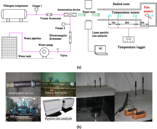
In these trials, the equipment was set up as in and the operation of the apparatus was checked, after which the nitrogen compressor, water pump and PSA were powered on. The water flow was maintained at 2 m3/h, the compressed nitrogen flow was set at 100 m3/h, and the V50 and V99 values were determined. Subsequently, the nitrogen flow was adjusted to 150, 260 and 360 m3/h and V50 and V99 were again determined. Following these measurements, a mass of burning coal was used as a combustion source and four temperature sensors were positioned in the combustion zone. The apparatus was operated using the previously determined optimum nitrogen and water flows and the flame temperature was recorded at 5 s intervals.
Figure 11. Experimental system (a) schematic figure; (b) physical photos.
4.2. Results and analyses
4.2.1. Atomization effects
As the mist enters the fire zone, it absorbs heat from the combustion. The heat absorption process of fine water mist droplets includes sensible heat exchange and latent heat exchange. Sensible heat exchange is the result of heat transfer due to heat conduction, convection and radiation due to temperature difference between environment and fog droplets. Latent heat exchange is the result of absorption or release of latent heat of vaporization by evaporation of fog droplets or condensation of water vapor. Total heat exchange is the sum of sensible heat exchange and latent heat exchange.
According to the mass exchange theory, when air is in direct contact with water, it forms a saturated air boundary layer whose temperature is equal to the surface temperature of fog droplets due to the irregular movement of water molecules near the place around fog droplets. Sensible heat exchange between air and fog droplets depends on the temperature difference between boundary layer and surrounding air, while wet exchange and latent heat exchange caused by it depend on the difference in molecular concentration of water vapor between them or the difference in water vapor pressure between them (Guo et al. Citation2019).
If we assume a tiny droplet surface of dS, sensible heat exchange between the tiny surface and the surrounding air can be expressed as EquationEq (18)(18)
(18) :
(18)
(18)
Since the difference of water vapor pressure in a relatively small temperature range can be replaced by the difference of moisture content with different wet exchange coefficients, the wet exchange capacity can be expressed as:
(19)
(19)
Wet exchange is accompanied by latent heat exchange, and the latent heat exchange capacity is:
(20)
(20)
The total heat exchange between the droplet and the fire area can be expressed as EquationEq (21)(21)
(21) :
(21)
(21)
EquationEq (21)(21)
(21) suggests that that more dispersed particles will have a larger specific surface area, and a faster heat transfer rate will result when the water quantity is constant.
Where dS is the Droplet surface, m2; dQx is Sensible heat exchange, J; αa,w is the Heat-exchange coefficient W m−2
K−1; Ta is the Air temperature, K; Tb is the Boundary layer temperature, K; dQq is the Latent heat exchange, J; qq is the Unit latent heat at temperature Tb, J
kg−1; dM is the wet heat exchange volume; σa,w is the wet heat exchange coefficient, kg
m2
s−1; da is the Moisture content, kg/kgdryair; db is the Moisture content of the air layer, kg/kgdryair; dQz is the Total heat exchange, J.
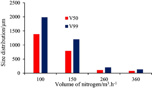
The data in demonstrate that both V50 and V99 decreased with increasing nitrogen flow. Because the optimal distribution range for class A coal fire extinguishment is between 500 and 1200 μm, the preferred nitrogen flow rate is 150 m3/h.
Figure 12. Water size distribution under different nitrogen volume.
4.2.2. Fire extinguishing performance
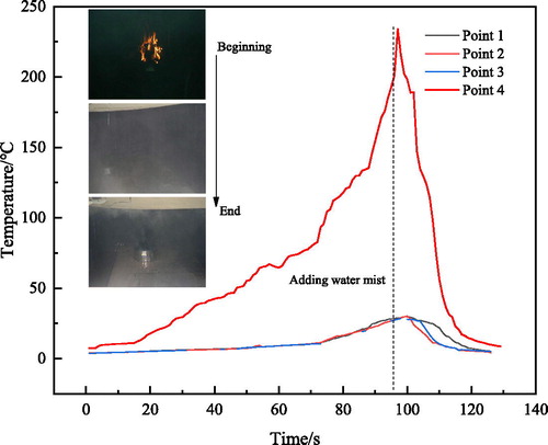
plots the temperatures at various points as functions of time. Prior to applying the water mist, the temperature increased in a steady manner. However, after applying the mist, the temperature suddenly increased over a short time span of approximately 1.5 s and then gradually decreased. This sudden rise in temperature is due to a disturbance of the flow field by the initial water mist, which strengthened the combustion velocity of the burning coal. Continued application of the mist absorbed heat to cool the flame zone, such that the temperature decreased gradually.
Figure 13. Changing of temperatures in sealed zone.
5. Conclusions
This work studied an atomization device with an optimized design and assessed the atomization performance and fire suppression effect. The following conclusions can be made:
The fire prevention technology of nitrogen-water mist in enclosed spaces is put forward. The technology to make nitrogen and water mist constitute the mixture gas liquid two phase fluid, in the limited space to form a three-dimensional full cover type fire mode, make full use of the water mist good heat and cooling ability and large flow rate of nitrogen suffocation ability, thus improve the effect of the fire, is an efficient technique in the coal mine fire prevention and treatment.
A new nitrogen - water mist atomizing device was developed. The structure and mechanism of the atomization device were described in detail. And flow field characteristics in the atomization device were evaluated using numerical simulations and a laboratory model test. According to the research results, the optimal starter twist number is 3, and one blade is preferable.
Particle size distributions were characterized by determining V50 and V99 values at various flow rates in conjunction with Ck = 1, CL = 3 and Qw = 150 m3/h. The particle sizes were found to be in the range of 500–1200μm, and the associated mist rapidly reduced the combustion temperature in an enclosed space.
Disclosure statement
The authors declare no conflicts of interest.
Additional information
Funding
References
- Banerjee S C. 1985. Spontaneous combustion of coal and mine fire. Rotterdam: A.A. Balkema, p. 101–122.
- Cen KF, Fan JR. 1990. Theory and calculation of gas-solid multiphase flow in engineering. Hangzhou: Zhejiang University Press.
- Dunand A, Carreau J L, Roger F. 2005. Liquid jet breakup and atomization by annular swirling gas jet. Atomiz Spr. 15(2):223–247.
- Fan WL. 2011. Center air path bifurcated multiplex high efficiency atomizing device: CN 102189051B [P].
- Grant G, Brenton J, Drysdale D. 2000. Fire suppression by water sprays. Prog Energy Combust Sci. 26(2):79–130.
- Guo CW, Zhou JL, Liu X. 2013. Pulsed water jet suction atomizing device: CN103447184 B [P].
- Guo Q, Ren W, Zhu J, Shi J. 2019. Study on the composition and structure of foamed gel for fire prevention and extinguishing in coal mines. Process Saf Environ Prot. 128:176–183. ():
- Guo Q, Ren W. 2019. Atomization parameters and fire suppression characteristics of water mist in simulated roadway. Geomat Nat Hazards Risk. 10(1):1529–1541.
- Guo Q, Ren WX, Lei B. 2018. Properties of foamed gel for coal ignition suppression in underground coal mine. Combust Sci Technol. 191(8), 1294–1308.
- Jones A, Nolan P F. 1995. Discussions on the use of fine water sprays or mists for fire suppression. J Loss Prev Process Ind. 8(1):17–22.
- KongB, Zenghua L, Enyuan W, et al. 2018. An experimental study for characterization the process of coal oxidation and spontaneous combustion by electromagnetic radiation technique. Process Saf Environ Prot. 119:285–294.
- Li L, Qiu XY. 2008. numerical simulation of weakly rotating flow in a turbid-water hydraulic separation clearwater unit. J Hydropower. 27(2):103–106.
- Liang CL. 2010. Several Colliery Fire Accident Cause Analysis and Prevention Measures. Sci Technol West China. 09(13):18–19.
- Liang Z, Wu SH, Ren LC. 2007. On the selection of turbulence model in numerical simulation of hydrocyclone flow field. Nat Gas Ind. 27(3):119–121.
- Liu JZ. 2009. Science and Technology Demand and Countermeasures for Coal Mine Safety in China. Coal Mine Saf. 40(8):112–115.
- Liu NL, Zhang X. 2006. Analysis of jet and droplet distribution characteristics of water mist nozzle. National HVAC Refrigeration Academic Proceedings. 150–152.
- Lu X, Zhu H, Wang D, Hu C, Zhao H, Huo Y. 2018. Flow characteristic investi-gation of inhibition foam used for fire extinguishment in the underground goaf. Process Saf Environ Prot. 116:159–168.
- National Fire Protection Association (NFPA). 2006. NFPA 750 Standard on water mist fire protection systems. 2006 Edition. MA: An International Codes and Standards Organization, 7
- Qi KC. 2017. Optimization design and test analysis of spray nozzle in collecting dust. Fluid Power Transm Control. 4:49–51.
- Ray S K, Singh R P. 2005. Effect of water mist on open fire-a model study. Min Technol Trans. Inst. Min. Metall. A. 114(5):A1–A12.
- Ray S K, Singh R P. 2007. Recent. Developments and practices to control fire in underground coal mines. Fire Technol. 43(4):285–300.
- Shi G, Liu M, Guo Z, Hu F, Wang D. 2017. Unsteady simulation for optimal arrangement of dedusting nitrogen duct in coal mine heading face. J Loss Prev Process. 46(3):45–53.
- Singh R.V, Tripathi D.D. 1996. Fire fighting expertise in Indian coal mines. J Mines Metals Fuels. 44(6):210–212.
- Tang Y, Si S, Zhong X. 2019. Experimental investigation of the performance of an effective self-suctioning water mist generator for controlling underground coal fires. Process Saf Environ Prot. 126:98–105.
- Tian ZJ. 2009. Research on the Theory and technology of foamed gel using for fire prevention. JiangSu XuZhou:China University of Mining and Technology
- Walter B. 1981. Fighting mine fires with nitrogen in the Germany coal industry. Mine Eng. 140(296): 797–804.
- Wang Z, Wang W, Wang Q. 2016. Optimization of water mist droplet size by using CFD modeling for fire suppressions. J Loss Prev Process Ind. 44(11):626–632.
- Wang ZB, Chen WM. 2006. Numerical simulation and analysis of flow field characteristics in hydrocyclone. J Sichuan Univy (Eng Sci Ed). 38(3):59–64.
- Wu J, Liu X. 2011. Risk assessment of underground coal fire development at regional scale. Int J Coal Geol. 86(1):87–94.
- Xu YQ. 2006. Coal Mining. China University of Mining and Technology Press, Xuzhou
- Yu M, Wan S, Xu Y, Zheng K, Liang D. 2016. The influence of the charge-to-mass ratio of the charged water mist on a methane explosion. Journal of Loss Prevention in the Process Industries. 41(3):68–76.
- Zhang Y, Liu SY. 2005. Application of the Reynolds Stress Model to the Calculation of Three-Dimensional Turbulent Flow-Field. J Aerosp Power. 20(4):572–576.
- Zheng H. 2014. Research on Chinese coal production peak and sustainable utilization of coal resources. Sichuan, Chengdu: China Southwestern University of Finance and Economics
- Zhong H, Chen G, Jiang S. 2016. A novel method for evaluation of fire prevention by using water curtain with large droplets. J Loss Prev Process Ind. 43(7):585–592.
- Zhuang Z, Liang J, Luo CT. 2017. Droplet size distribution of two-fluid airblast atomizing nozzle in MTP reactor. Chem Eng (China). 45(08):42–48.