
 ?Mathematical formulae have been encoded as MathML and are displayed in this HTML version using MathJax in order to improve their display. Uncheck the box to turn MathJax off. This feature requires Javascript. Click on a formula to zoom.
Abstract
In fully mechanized caving mining, the earlier the top coal enters the limit-equilibrium zone, the easier it is for leakage to be induced in front of the support. As the dip angle of the seam increases, the leakage of the top coal in front of the support drastically reduces the stability of the stope support–surrounding rock system. In this study, theoretical analysis, a physical simulation experiment, a numerical simulation, and field measurements were performed to consider the influence of the coal seam dip effect on the gradual deterioration of top coal for the first time, and quantitative characterization of the limit equilibrium boundary of top coal was realized based on analysis of the continuous damage medium mechanics. The results show that the two boundaries exhibit a consistent, asymmetric ‘double arch’ distribution along the incline. The top coal in the inclined upper-middle region of the working face is the first to enter the limit-equilibrium state, whereas the inclined upper and lower regions lag behind. The initial and final boundaries of the limit-equilibrium zone are distributed from 1.24 to 3.04 m and from 0.19 to −1.95 m in front of the coal wall, respectively. The distribution of the limit-equilibrium zone boundary was verified by the leakage times of the top coal in the working face. These results could provide reference information for evaluating stope support–surrounding rock systems in fully mechanized caving mining with steeply dipping coal seams.
1. Introduction
In China, fully mechanized longwall caving mining technology in steeply dipping coal seams (SDCSs) has progressed considerably in recent years. Because the broken top coal can easily leak before the support, the support–surrounding rock system becomes unstable, which severely compromises the safety and efficiency of stope production. Top coal is the only medium between the support and roof, and its mining mechanical behaviour is the main factor affecting the stability of the support–surrounding rock system. According to prior research, the evolution of the mechanical behaviour of top coal can be classified into elastic, plastic, and loose-block zones, which reflect the mechanics of coal in different mining stages (Yan and Wu Citation1996). However, it is difficult to express these stages with a unified constitutive relation, and the limits of each area cannot be quantified. Thus, suitable guidelines regarding coal production are not available.
Based on the limitations of early research, scholars discussed the gradual deterioration of top coal from the perspectives of crack evolution on the micro–macro scale, damage development, migration, and fragmentation of top coal. Xie and Zhao (Citation2001) and Chen and Xie (Citation2000, Chen et al. Citation2002a, Chen et al. Citation2002b) defined top coal as a type of quasicontinuous medium between continuous and discontinuous media and performed analyses based on the damage mechanics changes in the damage factor of top coal under different stress boundary conditions. Alehossein and Poulsen (Citation2010) used limit equilibrium theory to analyze the stress state of top coal in front of a coal wall. They studied the relationship between the crack propagation process and top-coal type, as well as the magnitude and direction of the principal stress, and determined the stress-driving mechanisms of crack propagation in different mining stages. The aforementioned studies have been used as references for the evaluation of top coal cavability (Wang et al. Citation2014, Citation2019; Wang and Wang Citation2018). To explore the relationship between the top coal displacement distribution and the degree of damage from the perspective of large macroscopic deformation, numerical simulations and field observations have been conducted (Yan and Wu Citation1996; Khanal et al. Citation2011). Yasitli and Unver (Citation2005) and Tien et al. (Citation2018) studied the stress distribution and failure process of top coal in longwall top-coal caving mining by numerical calculation. These previous studies have laid a theoretical foundation for the discussion of the gradual deterioration of top coal. However, the initial boundary position of the top coal limit-equilibrium state could not be determined in these works.
Furthermore, the existing research is limited to flat or gently inclined coal seams and does not address the mechanism through which the coal seam dip angle influences the mining stress path. When the dip angle is large, the overlying strata structure and mining stress distribution in the stope show new characteristics, which affect the dynamic mining behaviour of top coal. Wu et al. (Citation2010, Citation2017, Citation2020) and Xie et al. (Citation2018; Xie and Wu Citation2019) found that the gangue that collapses in the longwall working face of an SDCS is unevenly filled in the goaf, the roof is asymmetrically broken, and the bearing structure and movement of the overlying strata exhibit intensive leaps, time sequences, and asymmetric shapes. Kulakov systematically studied the law of mine pressure behaviour in a steep coal seam working face. Luo et al. (Citation2016) formulated an axis equation that describes the overlying strata stress arch and determines the basic form of the stress-space arch shell under the influence of the dip angle. Based on three-dimensional physical experiments and numerical simulations, Wang et al. (Citation2016a, Citation2016b) discovered the spatial envelope structure of a stress-caving arch shell in the overlying strata at an SDCS longwall stope. The rock mass structure mechanism that controls the mining stress in the clamping range of ‘double arches’ was determined, and the rock mass-bearing structure was defined as the critical zone in the overlying strata; accordingly, the equilibrium conditions of the rock mass structure in the critical zone in the overlying strata were clarified.
In recent years, researchers have reached a consensus regarding the failure mechanism of top coal. First, top coal is neither a completely continuous medium nor a completely discontinuous medium; thus, it is not suitable to divide the failure process of top coal simply based on the traditional elastic–plastic theory. Second, the failure process of top coal essentially involves coal fracture expansion, evolution, and gradual deterioration of mechanical properties. This process is similar to the basic process of macroscopic material damage and can be analyzed from the fundamental viewpoint of damage.
To produce a fully mechanized caving face with an SDCS efficiently and provide a safe working environment for workers, it is necessary to study the boundary of the top coal limit-equilibrium zone. The determination of the boundary position of the top coal limit-equilibrium zone in fully mechanized caving with an SDCS ensures that there is a targeted area for coal mining, the coal caving process, and protection of the working face, which greatly improves the working efficiency and reduces accidents.
In this study, the gradual deterioration of the top coal during mining was explained by continuum damage mechanics. The quantitative characterization of the top-coal damage state at the boundary of the limit-equilibrium zone was realized by combining the generalized Hooke's law with the Hoek–Brown criterion. Considering Changshanzi (China) with an SDCS as the research object, the evolution of macro-equivalent damage to the top coal at different critical-zone strata heights was determined based on physical experiments and UDEC numerical calculations. Furthermore, a method of determining the boundary-distribution form of the top coal limit-equilibrium zone under SDCS conditions was established; this method could provide a reference for evaluation of the ‘support–surrounding rock’ relationship in fully mechanized caving mining with an SDCS.
2. Macro-equivalent damage process of top coal
2.1. Basis of describing top-coal deterioration from the viewpoint of damage
The deterioration of the macro-mechanical properties of materials or structures due to irreversible changes in the microstructural defects (such as microcracks and micropores) under an applied external load is called damage. Previous studies have shown that the process from the start point in front of the coal wall to the failure state is essentially a process of initiation–development–expansion–penetration of internal cracks in coal under the influence of the dynamic evolution of the mining stress field (Yan et al. Citation1995). This process can be regarded as the evolution of internal cracks in coal from meso to macro-cracks. When a macro-crack forms, it gradually cleaves the top coal into cracked blocks of uniform scale as it propagates, causing the top coal to lose its bearing capacity, which is known as strength failure. In the process of its internal deterioration, the progressive failure of top coal conforms to the definition of damage; however, from the perspective of scale, progressive failure is a type of large deformation that leads from meso to macro-damage. Therefore, it is necessary to study the macro-mechanical properties of materials and the deterioration of structures from a macro-damage perspective based on phenomenology to avoid discussing the physical background of damage and the changes in the meso-structures of materials. The deformation range of top coal is relatively large, and there is an order of magnitude difference between the sizes of the macro-cracks and top coal. Therefore, it is feasible to equate the process of initiation–development–expansion of internal cracks in coal with the cumulative process of internal damage in top coal, which is consistent with the basis of damage mechanics.
2.2. Definition of macro-equivalent damage of top coal
The development of continuum damage mechanics has provided a new theoretical basis for studying the constitutive relation of top coal. Unlike traditional elasticity, plasticity, and fracture mechanics, continuum damage mechanics can be used to establish the relationship between the internal damage and macro-deterioration of coal. Combining damage theory and elastic–plastic theory enables the advantages of both theories to be employed and compensates for the disadvantages of both, thereby reasonably reflecting the stress–deformation responses of materials.
To facilitate continuous analysis of the nonlinear stress–strain relationship during coal loading, we consider the hypothesis of strain equivalence in damage mechanics, which states that the strain caused by the stress acting on damaged materials is equivalent to the strain caused by the effective stress acting on nondestructive materials. According to this assumption, if there exists a nondestructive ideal elastic material, it will always exhibit elastic characteristics during loading, and its stress–strain characteristics will be different from those of a coal sample, as shown in .
Figure 1. Differences in stress and strain characteristics between an ideal elastic material and coal.
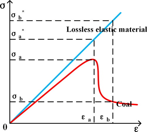
Before the material yields, when the strain of coal reaches εa, the internal stress is σa. Under strain εa, the internal and effective stresses of the nondestructive material are σa* and σa, respectively. Similarly, σb and σb* are the effective and nominal stresses corresponding to strain εb, respectively. The strain generated during the loading process of the nondestructive material and the corresponding nominal stress always follow a linear elastic relationship according to the generalized Hooke’s law, as expressed in EquationEq. (1)(1)
(1) :
(1)
(1)
where E is the elastic modulus of coal, μ is the Poisson’s ratio of coal, ε is the strain at the ultimate strength of the coal sample, σ1* is the maximum nominal principal stress of the coal sample, and σ2* and σ3* are the second and third nominal principal stresses of the coal sample, respectively. The development and expansion of internal cracks in coal weakens its macro-mechanical properties. The relationships between the nominal stress σ* and effective stress σ are
(2)
(2)
where σ1 is the maximum principal stress of the coal sample, D is its damage variable, and σ2 and σ3 are its second and third principal stresses, respectively. Substituting EquationEq. (2)
(2)
(2) into EquationEq. (1)
(1)
(1) yields the following expression:
(3)
(3)
EquationEquation (3)(3)
(3) reflects the damage process of coal samples and conforms to the stress boundary change and the gradual deterioration of coal under the influence of mining activity. Therefore, the damage variable D of coal samples can be equivalently replaced with the macro-equivalent damage variable DL of top coal:
(4)
(4)
At present, it is difficult to establish an accurate function to quantify the damage suffered by top coal. However, the damage can be determined in terms of the change in the displacement of top coal when it transitions from the original state to the loose state. The displacement of top coal is essentially the degree of separation of the rigid unit on which the observation point is located, relative to the reference point. This displacement indirectly and macroscopically reflects the development and opening degree of internal cracks in the coal body. The greater the displacement, the larger the volume occupied by voids inside the top coal, and the smaller the volume of the internal structure. As macro-damage to the top coal becomes more severe, the degree of macro-damage is reduced, and vice versa. The ratio of the displacement of top coal at any time and position to the displacement of the top-coal body during caving is represented by the macro-equivalent damage variable DL:
(5)
(5)
where SL is the displacement of top coal from the working face L and SF is the displacement when the top coal enters the critical loose-block-medium state (immediately before the abrupt increase in the displacement of top coal). Owing to the different directions of crack opening, the top-coal body exhibits both horizontal and vertical movements. According to the geometric relationship, the displacement of the top coal is
(6)
(6)
where SVL and SHL are the vertical and horizontal displacements of the top coal from the working face, respectively.
2.3. Top coal damage process and stress boundary conditions during mining
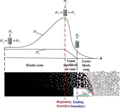
Under the effects of mining activities, top coal undergoes the process of initiation–development–expansion–penetration from the original state to the final loose-block state. This process can be regarded as the evolution of internal cracks in coal from the mesoscale to the macroscale. Under the action of the front abutment pressure, the mesopores in the coal body become budded and start to develop. The development scale and density of cracks at the peak abutment pressure begin to reduce the macro-strength of the top coal. We propose that macro-cracks are formed in the top coal during this phase and that they accelerate the damage accumulation, inducing a transition of the mechanical behaviour from the elastic state to the limit-equilibrium state. After the top coal enters the limit-equilibrium state, axial and radial stresses are unloaded; the macro-cracks are further stretched, expanded, and connected; and macro-damage accumulates rapidly. Finally, the top coal is cut into loose blocks, and the residual axial bearing capacity is maintained only by the friction between blocks and the limiting effects of external constraints. Meanwhile, the lateral constraints disappear. At this time, the macro-cracks in the top coal become well-connected, and the macro-damage accumulates and reaches its maximum density. Soon thereafter, the top coal enters the loose-block-medium state from the equilibrium state limit.
The original rock stress can be decomposed into vertical and horizontal stress components. According to the in situ stress database of Chinese coal mines (Kang et al. Citation2019), the vertical stress is essentially equal to the weight of overlying strata, whereas the horizontal stress is complex. Based on a large number of in situ stress data of coal mines, the relationship between the ratio of the average horizontal to vertical stress and the buried depth has been determined:
(7)
(7)
where Kav is the ratio of the average horizontal to vertical stress and H is the buried depth of the coal seam.
Owing to the complex distribution of the initial underground and mining stress fields, stress fields cannot be analyzed and described accurately. Thus, the following assumptions are necessary:
With a continuous increase in the front abutment pressure, internal macro-cracks form in the top-coal body, which then enters the limit-equilibrium state. The bearing capacity of the unit coal body reaches its limit. The confining pressure starts to unload from the peak abutment pressure and decays approximately linearly (Xie and Zhao Citation2001).
After being completely cut by the connecting macro-cracks into nonmechanically connected blocks, the top coal enters the discontinuous loose-block-medium state from the limit-equilibrium state. The axial stress of the top coal decreases to the single-axial residual strength at this instant, and the confining pressure drops to zero (Gao et al. Citation2018).
illustrates the evolutions of the mechanical behaviour of top coal during mining and the stress boundary conditions at the boundary of the limit-equilibrium zone.
Figure 2. Gradual deterioration process of top coal during mining.
2.4. Macro-equivalent damage of top coal at the boundary of the limit-equilibrium zone
The top coal in the limit-equilibrium zone is a fractured rock mass that obeys the Hoek–Brown criterion (Hoek and Brown Citation1980):
(8)
(8)
where σ1 is the axial ultimate principal stress when top coal is damaged, σ3 is the lateral ultimate principal stress when top coal is damaged, σc is the uniaxial compressive strength of top coal, and m and s denote the conditions of the structural surface and the rock mass empirical constant related to the quality and rock mass structure, respectively. By substituting EquationEq. (8)
(8)
(8) into EquationEq. (4)
(4)
(4) , we derived the macro-equivalent damage variable of top coal:
(9)
(9)
At the end boundary of the limit-equilibrium zone, σ3 = 0. Based on EquationEq. (9)(9)
(9) , the macro-equivalent damage variable of top coal can be obtained, as expressed in EquationEq. (10)
(10)
(10) :
(10)
(10)
3. Engineering background
The main coal seam of the Changshanzi Coal Mine of the Yaojie Coal and Electricity Group Co., Ltd. in China is No. 2 coal. Studies of the 1123 fully mechanized longwall caving face with an SDCS in Changshanzi Coal Mine have revealed that the average thickness and average inclination angle of the coal seams in the working face are 10 m and 36°, respectively, and that the coal seams are relatively stable. The design strike length of the working face is approximately 530 m, and the inclined length is approximately 100 m. The fully mechanized longwall top-coal caving mining method is utilized for the working face, and the roof is managed using all caving methods. The cutting height of the working face is 3 m, the caving height is 7 m, and the mining-to-caving ratio is 1–2.33. lists the physical–mechanical parameters of the coal seam, roof, and floor.
Table 1. Coal and rock mechanical parameters.
3.1. Experiment on the distribution of critical-zone strata
In the process of longwall mining in an SDCS, the secondary distribution of the surrounding rock stress causes the overlying strata to crumble and form a caving arch. Regardless of the strike or inclination, the boundary contour of the caving arch is consistent with that of the stress arch, and the edge is located inside the stress arch. The rock strata between the stress arch and caving arch control the entire stope. The rock mass structure formed by the rock strata in this range is called the critical zone of the stope (Wang et al. Citation2017). In an SDCS stope, the rock mass structure controlling the movement of the overlying strata is not limited to strata in any particular horizon, but rather constantly changes as a function of the stress constraint and boundary conditions. The distribution of this structure spans several strata along the direction of the incline. Therefore, determining the distribution of the critical-zone strata in the overlying strata of the working face is a prerequisite for analyzing the gradual deterioration of top coal in a fully mechanized caving face with an SDCS. The critical-zone strata in the direction of the incline are affected by specific factors, such as the coal seam dip angle, mining height, uneven filling of the goaf, and lithology of the overlying rocks. The distributions of the critical-zone strata in different working faces must be determined through physical experiments.
3.1.1. Experimental model
A physical simulation experiment was conducted in this study, wherein a variable-angle simulation experiment frame with dimensions of 2,150 mm × 200 mm × 1,800 mm (l × w × h) was used. According to the size of the working face and the attributes of the research problem, the geometric similarity ratio was determined to be 1:100. Based on similarity theory, the density, stress, load, and time similarity parameters were determined. lists the specific calculation results.
Table 2. Physical simulation parameters used in the test.
The materials needed for the physical simulation experiments included river sand, gypsum, lime powder, mica sheet, and water. River sand was the main construction material, gypsum and lime powder were the bonding materials, and mica sheet was the layering material for the model. All the materials were mixed with each other in a certain proportion to simulate rock strata. According to the similarity relationships between various parameters of the model and prototype, different proportions of similar materials were selected for rock layers with different lithologies. lists the proportions and laying thickness of the similar materials, and shows the laid model.
Figure 3. Similarity experimental model of fully mechanized top-coal caving face along the inclined direction.
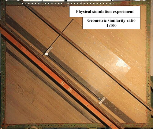
Table 3. Material ratios and laying thicknesses of the models.
3.1.2. Experimental process
According to the geometric similarity ratio Cl (1:100), the design excavation length of the working face of the model, mining height, and caving height were set to 100 cm, 3 cm, and 7 cm, respectively. The specific experimental steps were as follows:
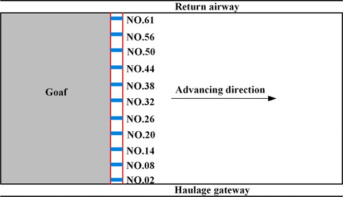
Excavation of return airway and haulage gateway. The return airway and haulage gateway were located at the inclined upper and lower parts of the working face, respectively. Considering the boundary effect, excavation was conducted 600 mm away from the model boundary, and the lengths and widths of the cross-sections of the return airway and haulage gateway were set to 50 mm and 30 mm, respectively.
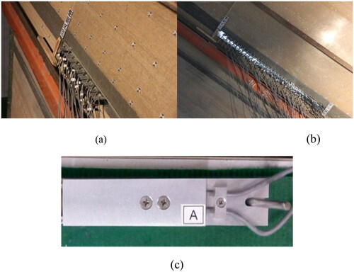
Open-off cut. Mining was conducted from the upper to the lower parts along the inclined direction of the working face. The support was constructed and adjusted to the initial support state every time a region was excavated, until all supports in the working face had been arranged. A total of 30 simulated sensing supports with adjustable heights were installed, as shown in .
Mining and caving. The mining height of the coal seam was 30 mm. When the working face advanced by 10 mm, the support was repeatedly raised and lowered for six rounds after installation, to simulate the advancing of the working face. The sensing support was not raised any further when the load reached 2.56 kg, and the interval between successive height changes was 48 min. The working face immediately receded from the upper to the lower parts after 20 mm advancement at each instant, to simulate caving. When the top coal collapsed, the caved and accumulated coal was removed, which was regarded as the top coal for transportation. Furthermore, the third step was iterated until the mining had been completed.
Figure 4. Open-off cut process of fully mechanized top-coal caving face: a. process onset from the return airway, b. end of process, and c. simulated support.
3.1.3. Experimental results
SDCSs are affected by the dip angle of the coal seam during mining and caving, and the overlying strata are uneven during caving. The overlying strata in the inclined upper region of the working face cave earlier than those in the lower region. When the overlying strata in the upper region collapse, the collapsed gangue will slip along the floor to the lower region of the working face, which will accompany the phenomenon of flying gangue. Thus, the overlying strata in the upper region collapse completely and separate, whereas the overlying strata in the lower region collapse insufficiently and rotation occurs under the hinging action of the lower overlying strata. Finally, filling phenomena of different degrees appear along the inclined direction of the working face.
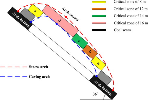
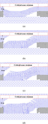
After the completion of mining in the working face and after the top coal has completely caved, the strata gradually collapse with time before breaking and sinking, the goaf is gradually filled and compacted, and the caving shape tends to stabilize, as shown in . Along the inclined direction of the working face, the critical-zone strata between the lower and upper regions continually migrate upward until they reach the upper part of the main roof; moreover, the critical-zone strata between the upper-middle and upper regions migrate downward. The vertical height of critical zone A (highlighted in yellow) from the coal seam is 8 cm, and the vertical heights of critical zones B (orange), C (green), and D (pink) from the coal seam are 12, 14, and 16 cm, respectively ().
Figure 5. Caving characteristics of the overlying strata along the direction of the incline of the working face.
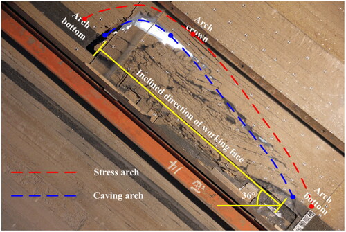
Figure 6. Distribution of critical-zone strata heights in the inclined direction of the working face.
3.2. Numerical analysis of top coal migration characteristics
3.2.1. Numerical model and experimental process
UDEC is a discrete element-based numerical analysis software package that offers unique advantages in analyzing the movement and deformation of rock mass containing internal cracks and weak planes. According to the critical-zone stratum height of the 1123 working face in the inclined direction, five sections parallel to the normal direction of the coal seam were cut along the strata of A, B, C, and D, and the UDEC plane model was established within each section, as shown in . Each model could be used to analyze the migration characteristics of top coal by controlling the corresponding critical-zone strata height.
Figure 7. Division basis of modeling in the numerical calculations.
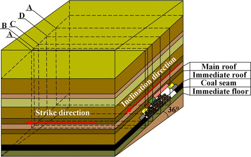
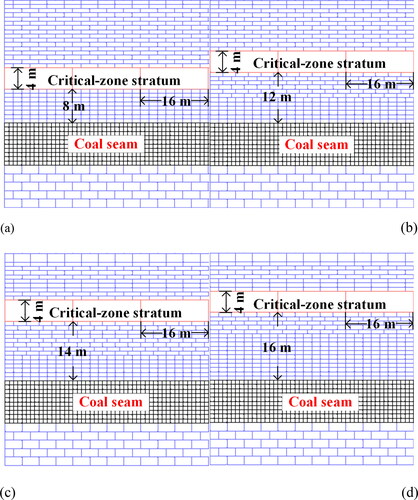
The role of the critical-zone strata in SDCS is consistent with that of the key stratum in near-horizontal coal seams. Because it is necessary to form a hinged structure to bear the load of the overlying strata, the critical-zone strata should have a large fracture step, large thickness, and high strength. Critical-zone stratum A is located in the interbedded fine sandstone and mudstone, Critical-zone strata B and C lie in the lower part of fine sandstone, and Block D is in the upper part of the fine sandstone. Combining the joints of the critical-zone strata in the physical simulation experiment and the periodic weighting step of the working face, the unit length and width of the critical-zone strata were 16 m and 4 m, respectively. To observe the collapse characteristics and migration laws of the overlying strata clearly, the unit sizes of other strata were divided into three types according to the buried depth. The unit sizes from the deep to the shallow regions were 4 × 1 m, 3 × 1 m, and 2 × 1 m (l × w).
The geometric dimensions of the five models were 200 × 100 m (l × w), and the buried depths were 236, 246, 260, 268, and 274 m, respectively. The difference between models 1 and 5 was negligible because their critical-zone strata had the same height and because the difference between the overlying strata load caused by the difference between the buried depths was small. Therefore, the five models were simplified into four models for analysis. The distances from the critical-zone strata to the roof for the four models were 8, 12, 14, and 16 m.
The upper boundary was set as the free boundary, and the bottom boundary and the boundary on either side were set as the fixed boundaries (). The Mohr–Coulomb constitutive model was used for the block material, and the Coulomb sliding model with surface contact was selected as the joint constitutive model. lists the mechanical parameters of each rock stratum.
Figure 8. Numerical models with different critical-zone strata. Critical zones of a. 8 m, b. 12 m, c. 14 m, and d. 16 m.
The measurement point was set 50 m in front of the coal wall of the open-off cut. The height of the measurement point from the floor was 4 m, and it was used to monitor the horizontal and vertical displacements of the top coal during mining. The process of mining and caving in the working face simulated by the model can be divided into four steps. The first step was used to simulate the open-off cut. In practice, the cross-sectional width and height of the open-off cut are 6 m and 2.6 m, respectively. In the model, the open-off cut was simulated by deleting blocks. The second step involved the processes required for the model to reach equilibrium. The third step entailed the mining of the lower coal seam with a mining height of 3 m. The fourth step was related to the recovery of the coal seam after removal of the top coal, with the caving height set to 7 m. The mining-to-caving ratio range was 3–7. After mining and caving had been completed, the third and fourth steps were repeated in the subsequent cycle until the entire mining process had been completed. The cycle was completed using the built-in programming language (FISH) in the UDEC model.
3.2.2. Collapse form of overlying strata and displacement characteristics of top coal
shows the collapse forms of the overlying strata in fully mechanized top-coal caving under different critical-zone strata heights. In , the critical-zone strata do not collapse during coal seam mining and caving, but only sink in the vertical direction. Because the lithology of the immediate roof is carbon mudstone, it can easily fall along a weak surface or fissure. In the coal seam mining process, immediate roof collapse occurs along with the caving of the top coal. Above the open-off cut, the immediate roof was cut, resulting in the separation between the critical-zone and collapse strata. Because of the interaction between the blocks in strata, the collapsed strata and intact strata form a masonry beam structure. With increasing critical-zone stratum height, the collapse trend of the overlying strata does not change. As the strata between the critical-zone strata and coal seam increase, the top coal is progressively loaded at increased quantities.
Figure 9. Collapse patterns of overlying strata with different critical-zone strata. Critical zones of a. 8 m, b. 12 m, c. 14 m, and d. 16 m.
The vertical and horizontal displacements at the top-coal layer at 4 m were obtained based on the measurement points. The vertical and horizontal displacements acquired at the measurement points were introduced into EquationEq. (6)(6)
(6) to obtain displacements SL1, SL2, SL3, and SL4. shows the evolution of the top-coal displacement with its distance from the coal wall of the working face at different critical-zone strata heights.
Figure 10. Top-coal displacement characteristics in different critical-zone strata.
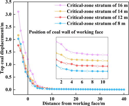
The numerical calculation results show that when the critical-zone stratum height is 8 m, the starting position of top-coal displacement is 7 m in front of the coal wall, and the displacement changes slowly within the range of 2–7 m from the coal wall and starts to increase abruptly at 2 m from the coal wall. At critical-zone stratum heights of 12, 14, and 16 m and starting positions of the top-coal displacements ranging from 9, 10, and 10 m in front of the coal wall, respectively, the position of the top-coal displacement sharply increases to 3, 3, and 4 m in front of the coal wall, respectively. With increasing critical-zone stratum height, the distance of the starting position of the top coal is increased, and the position where displacement suddenly increases is farther away from coal wall.
3.2.3. Macro-equivalent damage evolution of top coal
When the displacement at the top-coal caving time is known, the macro-equivalent damage variable at any position before top coal caving can be obtained. Before and after caving, the top-coal vertical displacement increased abruptly, which signifies the free fall of the top coal. Therefore, the beginning of the sudden increase in this vertical displacement can be considered as the instantaneous position of top coal caving. In the four groups of models, when the critical-zone stratum heights are 8, 12, 14, and 16 m, the vertical displacements at the instant of the sudden change in the top coal are 0.792, 1.042, 1.041, and 0.866 m, respectively, and the corresponding horizontal displacements are 0.771, 0.737, 0.865, and 0.846 m, respectively. The average SF of the final displacement of the top coal at the height of each critical-zone stratum before caving is approximately 1.13 m. Substituting the instantaneous displacement and SF of top coal at each instant in into EquationEq. (5)(5)
(5) revealed the evolution characteristics of the macro-equivalent damage variables of different critical-zone strata, as shown in .
Figure 11. Evolution of macro-equivalent damage variables with different critical-zone strata.
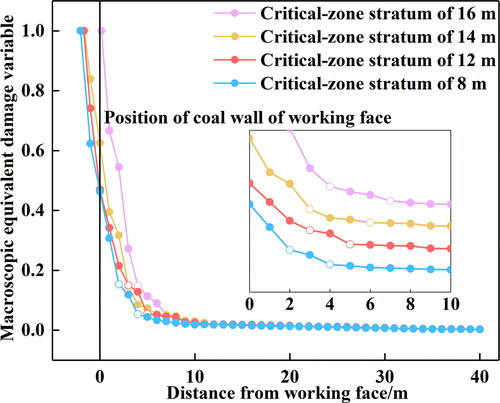
As is evident from , the evolution of macro-equivalent damage of the top coal is similar to that of the displacement. When the critical-zone stratum height is 8 m, the evolution of the macro-equivalent damage variable at 4 m from the top coal to the coal wall accelerates abruptly. This finding may mean that macro-cracks had already formed in the top coal and accelerated the damage. The evolution trend of the macro-equivalent damage at 2 m from the top coal to the coal wall becomes steeper, which may indicate that the macro-cracks in the top coal were connected to each other at that instant. Once the external constraints of the top coal have weakened or disappeared, the macro-equivalent damage will increase rapidly and will soon thereafter enter the discontinuous medium state of the loose-block zone. When the critical-zone stratum height is 12, 14, and 16 m, the distance from the coal wall when macro-cracks are formed is 5, 6, and 7 m, respectively, and the distance from the coal wall when macro-cracks are connected is 3, 3, and 4 m, respectively. Typically, the higher the critical-zone strata, the earlier the moment of formation and connection of top coal macro-cracks, and the farther away the coal wall.
4. Top-coal limit-equilibrium zone boundary calculation
4.1. Initial boundary calculation
According to the engineering background, the average buried depth of the coal seam is 260 m. Combined with EquationEq. (7)(7)
(7) , it can be concluded that the horizontal pressure on the coal unit in the original state zone is equal to 1.1 times the vertical pressure, i.e. σ2 = σ3 = 1.1σ1 = 1.1γH.
At the first boundary of the limit-equilibrium zone, the radial stress σ3 = 1.1γH can be substituted into EquationEq. (9)(9)
(9) to obtain the macro-equivalent damage variable of the top coal:
(11)
(11)
where ε1 is the corresponding strain when the top coal is at its ultimate strength.
EquationEquation (11)(11)
(11) formulates the macro-equivalent damage variable characterization method when macro-cracks are formed. Parameters μ, σC, E, ε, and m must be determined. Two groups of coal samples were obtained from the Changshanzi coal mine for rock mechanical testing and controlled axial displacement loading at an axial strain rate of 0.001 mm/s. lists the test results for the two groups of coal samples.
Table 4. Mechanical parameters of the coal samples.
The average buried depth of the coal seam in the 1123 working face is 260 m, the comprehensive bulk density of the overlying strata is 2,500 kg/m3, and the uniaxial compressive strength of the coal seam is 10 MPa. The empirical constant m of the rock mass quality can be obtained according to the Hoek–Brown criterion:
(12)
(12)
The advanced abutment pressures of the top coal caving faces in the Dongtan Coal Mine, Xinglongzhuang Coal Mine, and Xinzhou Kiln Mine were measured, and the average value of coefficient k at the peak value of this pressure was 1.98 (Jin et al. Citation2001; Qin and Wang Citation2004; Huang et al. Citation2007). The value of m according to EquationEq. (12)(12)
(12) was 0.46.
Substituting m, σ1, σ3, σC, E, and ε into EquationEq. (11)(11)
(11) indicates that the value of s is far less than 1 and thus can be ignored. Hence, the macro-equivalent damage variable DL1 corresponding to the occurrence of macro-cracks in the top coal can be obtained:
(13)
(13)
In , the abscissa x corresponding to the point at which D is 0.27 is 1.24 m, i.e. when the critical-zone stratum height is 8 m, the top coal has a macro-crack at 1.24 m in front of the coal wall. By using the same analysis and derivation methods, we derived the distance from the coal wall when macro-cracks were generated in the top coal at different critical-zone strata conditions, as listed in .
Table 5. Distance from the coal wall when the top coal produces macro-cracks in different critical-zone strata.
4.2. End boundary calculation
For a complete rock material, the rock mass empirical constant s is unity. For a damaged rock, the value of this constant it is less than unity; for whole granular samples or aggregates of rock fragments, it is zero. The integrity of coal is relatively low, and the damage is serious. Many methods can be employed to determine s. The method that uses the rock mass rating (RMR) index is the one most suitable for engineering practice. Subject to the condition of disturbed rock, s can be expressed as shown in EquationEq. (14)(14)
(14) (Hoek and Brown Citation1997):
(14)
(14)
The rock mass quality m of the top coal deteriorated rapidly before caving. The RMR index consists of five indices: rock strength, rock quality designation (RQD), joint spacing, joint condition, and groundwater (Bieniaski Citation1973, Citation1989). According to the actual situation of the coal seam, the value corresponding to each index can be obtained by comparison with an RMR system classification table. The range of the RMR score is 0–100, and the quality of rock is better the higher the score. According to the geological report on the coal seam in Changshanzi Coal Mine, the uniaxial compressive strength of the coal is 10 MPa, the PQD value of the coal seam is less than 25, the opening degree is 1–5 mm, and the groundwater is seriously affected. The rock strength, RQD, joint spacing, joint condition, and groundwater scores are 2, 3, 5, 10, and 0 respectively, and the RMR value is 20. At this time, the strain of the top coal, i.e. ε2 in , was 0.008. By combining EquationEqs. (10)(10)
(10) and Equation(14)
(14)
(14) , the macro-equivalent damage variable can be expressed as
(15)
(15)
shows the distance from the coal wall when the macro-equivalent damage variable of top coal was 0.988 with different critical-zone strata. presents the specific values.
Table 6. Distance from the coal wall when the top-coal medium state is transformed in different critical-zone strata.
4.3. Boundary distribution of top-coal limit-equilibrium zone
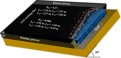
In the fully mechanized longwall caving face of Changshanzi 1123 with SDCS, when DL1 became 0.27, macro-cracks appeared in the coal, unloading began, and the elastic state entered the limit-equilibrium zone. The boundary was defined as the onset point of the limit-equilibrium zone. When DL2 was 0.988, the macro-cracks of the coal body became interconnected, the mechanical connection between blocks was lost, the radial stress decayed to zero, and the top coal blocks only relied on external constraints to maintain the residual bearing capacity. From the limit-equilibrium to the loose-block state, and once the external constraints had been removed, coal was quickly released in the form of free-state loose blocks. The boundary was defined as the end boundary of the limit-equilibrium zone. Based on the calculated data listed in and , illustrates the beginning and ending boundary-distribution forms of this zone at different critical-zone strata.
Figure 12. Boundary-distribution form of top coal limit-equilibrium zone in the 1123 working face in Changshanzi.
4.4. Field monitoring
In the fully mechanized top-coal caving face 1123 in Changshanzi, the leakage between supports is severe, as shown in . Because of the inclination effect, the gangue collapses and slides downwards, which leads to the support falling and affects the stope safety, as shown in . The working conditions of the supports in the 1123 working face were monitored for three months. The support top-coal leakage was monitored at a monitoring advancing distance of 140 m. A measuring station was set up at every sixth support from the inclined lower *2# support. There were 11 monitoring stations in total, as shown in .
Figure 13. Hidden dangers of on-site disasters in fully mechanized top-coal caving face. a. Leakage between support. b. Support falling.
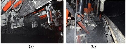
Figure 14. Measurement point layout in fully mechanized top-coal caving face.
Statistics were calculated based on the number and position of the top-coal leakage before and between the top-coal supports within a distance of 140 m from the working face. In total, 59 occurrences of top-coal leakage can be observed directly. Along the inclined direction of the working face, the number of top-coal leakages varied. Furthermore, the leakage of top coal had obvious regionalization characteristics along the inclined direction, as shown in .
Figure 15. Leakage distribution in fully mechanized top-coal caving face.
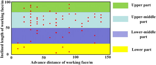
During monitoring along the inclined direction of the working face, there were 5 leakages between 0 and 20 m, 12 between 20 and 50 m, 34 between 50 and 80 m, and 8 between 80 and 100 m. As shown in , top-coal leakage is the most frequent in the middle–upper regions.
5. Discussion
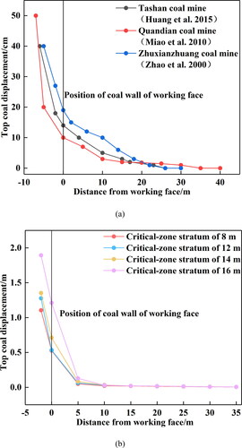
The research scope of this study was the nondestructive state of top coal. This state is also equivalent to the process that occurs before the top coal enters a loose-block or destructive state. In 1996, Yan and Wu (Citation1996) applied damage to top-coal caving for the first time and divided the top coal into three parts: elastic, plastic, and loose. The elastic and plastic parts are nondestructive. Based on the top-coal cavability, it can be considered that the top-coal migration process approximately conforms to the macro-damage principle. The displacement of top coal was monitored in real time in three mines, and the displacement curves of the top coal with the advancement of the working face were obtained (Zhao et al. Citation2000; Liao et al. Citation2010; Huang et al. Citation2015), as shown in . The overall trends of the three curves increase exponentially. The displacement curve of the top coal with the advancing working face was obtained based on UDEC numerical simulations in this study (). The overall trend is basically consistent with the engineering measurements. When the distance from the working face is large, the top coal hardly moves. When the distance from the working face is approximately 10 m, the top-coal displacement begins to change. As the distance from the working face decreases, the displacement increases. Xie and Zhao (Citation2001) and Chen and Xie (Citation2000) showed that the top coal in the fully mechanized top-coal caving mining was neither a completely continuous medium nor a purely loose medium, but rather a quasicontinuous medium. The failure state was attained only when it lost its mechanical contact with the surrounding rock mass. Before the failure state, the method of continuous medium damage mechanics could be used to study top coal.
Figure 16. Comparison of measured and numerical simulations of top-coal displacement characteristics. a. Measurement of top coal displacement in different mines. b. Measurement of top coal displacement in numerical simulations.
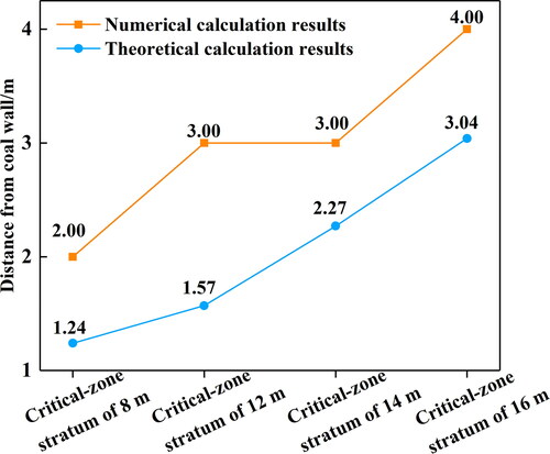
After the top coal entered the limit-equilibrium state, the strength deteriorated, crack development accelerated, and damage began to increase. According to the theoretical calculation, DL1 = 0.27 at the initial boundary of the limit-equilibrium zone of the top coal, and the corresponding positions at different critical-zone strata heights were 1.24, 1.57, 2.27, and 3.02 m away from the coal wall. The numerical simulation results show that the acceleration points of macro-equivalent damage of top coal at different critical-zone stratum heights are 2.00, 3.00, 3.00, and 4.00 m away from the coal wall and the corresponding macro-equivalent damage variables are 0.1533, 0.1496, 0.1444, and 0.1479, respectively. The theoretical calculation results are highly consistent with the numerical calculation results ().
Figure 17. Comparison between theoretical and simulation results of the beginning boundary in the limit-equilibrium zone.
The characteristics of the end-face leakage timing directly reflect the degree of top-coal breakage. The difference between the end-face leakage characteristics in different regions along the inclined direction verifies the asymmetry and time sequence of the top-coal deterioration process in the fully mechanized caving face with SDCS. The research results show that the final boundary of the limit-equilibrium zone of the inclined upper-middle part top coal in the 1123 working face is located 0.19 m in front of the coal wall, and the top coal is completely broken in loose-block media before it enters the support (). This finding is consistent with the field monitoring results indicating that the inclined upper-middle top coal is the most prone to facial leakage (), and the two sets of results are mutually verified. Similarly, in the upper and lower inclined parts wherein the final boundary of the top-coal limit-equilibrium zone is located, the leakage times of the end-face are reduced. This finding also confirmed the objective of achieving an asymmetric distribution pattern of the boundary of the top-coal limit-equilibrium zone.
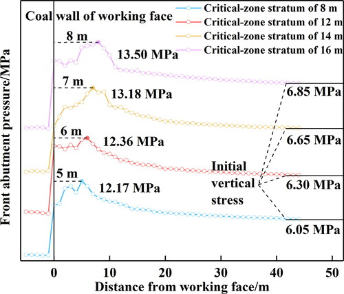
In this study, the SDCS was mainly investigated; the overlying rock mass structure was found to control the mining stress path that determined the deterioration process of the top coal. Under different critical-zone stratum heights, the distribution of front abutment pressure of top coal is different. presents the numerical calculation results. When the critical-zone stratum height is 8, 12, 14, and 16 m respectively, the peak value of the front abutment pressure is 12.17, 12.36, 13.18, and 13.50 MPa, respectively, and the distance from the coal wall is 5, 6, 7, and 8 m, respectively. With increasing critical-zone strata height, the peak value of front abutment pressure is larger and the distance from coal wall is farther.
Figure 18. Front abutment pressure distribution of top coal with different critical-zone stratum heights.
The critical-zone strata in the 1123 working face are asymmetrically distributed along the inclined direction, and the damage deterioration process of the top coal in different regions along the inclined direction exhibits an obvious time sequence. Determining the boundary of the limit-equilibrium zone plays an important role in the efficient mining of coal seam and the security of workers. The critical-zone strata in the inclined upper-middle part of the fully mechanized longwall top-coal caving face with SDCS are the highest, and the top coal enters the limit-equilibrium state and the loose-block state the earliest. When the top coal is broken above the canopy tip, it can easily flow out in the direction of the shield canopy after the caving of the top coal, resulting in the empty roof phenomenon and leading to instability of the support. Therefore, in the process of coal caving, any disturbance to the ‘high-risk area’ of top coal crushing should be minimized. The corresponding measures are formulated for the fully mechanized caving stope with SDCS. When caving in the fully mechanized caving face, the coal caving process should follow the ‘top-down’ principle, and the coal caving quantity should follow the principle of ‘less caving in the upper part, enough in the middle part, and as much as possible in the lower part.’ The effects of implementing these measures are obvious: worker safety is guaranteed and the support–surrounding rock system is more stable. In the process of advancing from 200 m to 340 m, 26 occurrences of top coal leakage were ascertained, which is 33 occurrences less than that in the 0–140 m advancing stage.
The research method of determining the boundary position of the top coal limit-equilibrium zone is not limited to SDCSs, but rather is also applicable to other coal seams. In future research, all kinds of coal seams will be studied, including ones with different dip coal seams, different roof and floor lithologies, and different coal seam thicknesses.
SDCSs are widely found in India, Russia, Uzbekistan, Belarus, Ukraine, and other countries besides China. Most countries are developing countries, and the demand for coal resource development is relatively strong. The relevant research results in this paper will help guide fully mechanized top-coal caving mining in SDCSs in these countries and have broad prospects for popularization and application.
In the study, the original rock stress of top coal was simplified to some extent. Because in situ stress monitoring was not conducted at this mine, it was difficult to obtain the radial stress. Thus, the radial stress was determined based on the combination of the fitting curve of the ratio of the vertical stress to the horizontal stress in the underground in situ stress database (Kang et al. Citation2019), i.e. σ2 = σ3 = 1.1σ1. In practice, under every set of geological conditions, the magnitude of the in situ stress is different. This feature affects the calculated damage variables at the initial boundary of the top-coal limit-equilibrium zone. In future work, the mining-induced stress of the coal and rock masses should be measured in real time during mining under different depth conditions, and the boundary conditions of top-coal stress should be defined. This work will help improve the calculation accuracy.
6. Conclusions
Based on the continuum mechanics of damage and the generalized Hookian law with damage and the Hoek–Brown criterion of rock mass, an expression for the degree of damage at the beginning and ending boundaries of the limit-equilibrium zone of top coal was obtained.
Because the damage process of coal itself is a ‘black box’ problem, which is difficult to monitor and analyze statistically, a method of describing the macro-equivalent damage using the ratio of instantaneous displacement of top coal to caving displacement was developed, and the corresponding relationship between the damage state of top coal and the spatial position was established.
The asymmetric distribution of the overlying strata in the critical zone of the fully mechanized caving face with SDCS was verified via empirical experiments, and the asymmetry and time sequence of the top-coal damage process subject to the influence of the critical zone were revealed via UDEC numerical calculations. The higher the critical-zone strata along the inclined direction, the earlier the top coal enters the limit-equilibrium and loose-block zones.
The macro-equivalent damage variables DL1 and DL2 were 0.27 and 0.988 at the initial and final boundaries of the limit-equilibrium zone, respectively, which was distributed between 1.24 m and 3.02 m in front of the coal wall and between 0.19 m in front and 1.95 m behind the coal wall, respectively, along the inclined part of the working face. The boundary of the limit-equilibrium zone was distributed in an asymmetric ‘double arch’ shape, and the crown of the ‘double arch’ was located in the inclined upper-middle part of the working face, Thus, it is more difficult to control the stope support–surrounding rock system in the inclined upper-middle part of the working face.
Disclosure statement
No potential conflict of interest was reported by the authors.
Data availability
The data used and generated in this study are available from the corresponding author upon reasonable request.
Correction Statement
This article has been republished with minor changes. These changes do not impact the academic content of the article.
Additional information
Funding
References
- Alehossein H, Poulsen BA. 2010. Stress analysis of longwall top coal caving. Int J Rock Mech Sci. 47(1):30–41.
- Bieniaski ZT. 1973. Engineering classification of jointed rock masses. J S Afr Inst Civ Eng. 15(12):335–344.
- Bieniaski ZT. 1989. Engineering rock mass classification. New York: Science Press; p. 180–250.
- Chen Z-H, Xie H-P. 2000. Damage mechanics analysis of abutment pressure distribution in fully mechanized top-coal caving face. J Rock Mech Eng. 19(4):436–439.
- Chen Z-H, Xie H-P, Lin Z-M. 2002a. Study on falling Ability of top coal during top coal caving by damage mechanics. J Rock Mech Eng. 21(8):1136–1140.
- Chen Z-H, Xie H-P, Wang J-C. 2002b. Numerical analysis of three-dimensional deformation and failure of top coal in fully mechanized top-coal caving mining. J Rock Mech Eng. 21(3):309–313.
- Gao M-Z, Zhang R, Xie J, Peng G-Y, Yu B, Ranjith PG. 2018. Field experiments on fracture evolution and correlations between connectivity and abutment pressure under top coal caving conditions. Int J Rock Mech Sci. 111:84–93.
- Hoek E, Brown ET. 1980. Empirical strength criterion for rock masses. J Geotech Engrg Div. 106(9):1013–1035.
- Hoek E, Brown ET. 1997. Practical estimates of rock mass strength. Int J Rock Mech Min Sci. 34(8):1165–1186.
- Huang B-X, Liu C-Y, Zheng B-S, Cheng Q-Y. 2007. Study on the distribution characteristics of coal pillar abutment pressure in super-long isolated island fully mechanized top-coal caving face. J Geotech Eng. 6:932–937.
- Huang Z-Z, Mao D-B, Liu Q-J. 2015. Study on the movement characteristics of extra-thick top coal in fully mechanized top coal caving mining with large mining height. China Coal. 41(11):41–43. +63.
- Jin Z-M, Wei J-P, Jin W-X. 2001. Distribution characteristics of abutment pressure in front of caving stope. J Taiyuan Univ Technol. 3:216–218.
- Kang H-P, Yi B-D, Gao F-Q, Lu H-W. 2019. In-situ stress database and distribution law of in-situ stress in coal mines in China. J Coal Sci. 44(1):23–33.
- Khanal M, Adhikary D, Baluse R. 2011. Evaluation of mine scale longwall top caving parameters using continuum analysis. Min Sci The. 21:787–796.
- Liao Y-F, Kang Q-Y, Wang X. 2010. Experimental study on top coal migration law of fully mechanized top-coal caving face in soft thick seam with large dip angle. Energy Technol Manage. 4:46–47. +55.
- Luo S-H, Wu Y-P, Liu K-Z, Xie P-S, Lang D. 2016. Study on spatial stress arch shell shape of longwall mining in steep seam. J Coal Sci. 41(12):2993–2998.
- Qin Z-C, Wang T-X. 2004. Distribution of abutment pressure in isolated fully mechanized top-coal caving face of deep well and its transmission law in floor. J Rock Mech Eng. 7:1127–1131.
- Tien DL, Oh J, Hebblewhite B, Zhang C-G, Mitra R. 2018. A discontinuum modelling approach for investigation of Longwall Top Coal Caving mechanisms. Int J Rock Mech Min Sci. 106:84–95.
- Wang J-C. 2018. Engineering practice and theoretical progress of top-coal caving mining in China. J Coal Sci. 43(1):43–51.
- Wang J-C, Wang Z-H. 2018. Propagating mechanism of top-coal fracture in longwall top-coal caving mining. J China Coal Soc. 43(9):2376–2387.
- Wang Z-H, Wang J-C, Wang K. 2019. Construction and application of top coal caving prediction model in fully mechanized top-coal caving mining. J Rock Mech Eng. 38(1):49–62.
- Wang H-W, Wu Y-P, Xie P-S, Cao P-P. 2016a. Critical zone conversion and rock structure balance characteristics in mining the steeply dipping seam. J Liaoning Technol Univ (Nat Sci). 35(10):1009–1014.
- Wang H-W, Wu Y-P, Xie P-S, Li Y-J, Cao P-P. 2016b. Quantitative filling characteristics of the waste rock and roof movement mechanism in the steeply inclined seam working face. J China Univ Min Technol. 45(5):886–892.
- Wang H-W, Wu Y-P, Xie P-S, Li Y-J. 2017. Stability analysis of rock mass structure in "critical zone" of mining in steeply dipping coal seams. J Min Saf Eng. 34(2):287–294.
- Wang J-C, Yang S-L, Li Y, Wei L, Liu H. 2014. Caving mechanisms of loose top-coal in longwall top-coal caving mining method. Int J Rock Mech Min Sci. 71:160–170
- Wu Y-P, Lang D, Wang Y-L. 2017. Regional interaction behaviour of “top coal-support”on fully-mechanized caving face in soft steeply dipping seam. J Xi’an Univ Sci Technol. 37(3):312–318.
- Wu Y-P, Xie P-S, Ren S-G. 2010. Analysis of asymmetric structure around coal face of steeply dipping seams mining. J China Coal Soc. 35(2):182–184.
- Wu Y-P, Yun D-F, Xie P-S, Fan ZD, Wang DF, Zhang YH. 2020. Progress, practice and scientific issues in steeply dipping coal seams fully-mechanized mining. J China Coal Soc. 45(1):24–34.
- Xie P-S, Wu Y-P. 2019. Deformation and failure mechanisms and support structure technologies for goaf-side entries in steep multiple seam mining disturbances. Arch Min Sci. 64(3):561–574.
- Xie P-S, Wu Y-P, Luo S-H, Wang HW, Lang D. 2018. Stability structural evolution of ladder roof and its stability analyses for a fully-mechanized working face with a large mining height in steeply inclined coal seams. J Min Saf Eng. 35(5):953–959.
- Xie H-P, Zhao X-Q. 2001. Analysis of continuous damage and failure of top-coal. J China Univ Min Technol. 35(4):323–327.
- Yan S-H. 2013. New consideration of mine strata pressure behaviour law and relationship between hydraulic powered support and surrounding rock in fully-mechanized top-coal caving mining. Coal Sci Technol. 41(9):96–99.
- Yan S-H, Meng J-S, Wu J. 1995. Mechanical method of top coal zoning in top coal caving mining. Coal Sci Technol. 12:33–37. ():
- Yan S-H, Wu J. 1996. Measurement of top coal movement and analysis of damage characteristics in top coal caving mining. J Rock Mech Eng. 15(2):155–162.
- Yasitli NE, Unver B. 2005. 3D numerical modeling of longwall mining with top-coal caving. Int J Rock Mech Min Sci. 42(2):219–235.
- Zhao X-Q, Chen Z-H, Cheng G-M, Shen Z-W, Wu J. 2000. Actual measurement and analysis of top coal movement in pre-mining top and fully mechanized top coal caving mining in "three soft" thick seam. Coal Sci Technol. 28(12):35–37.