
 ?Mathematical formulae have been encoded as MathML and are displayed in this HTML version using MathJax in order to improve their display. Uncheck the box to turn MathJax off. This feature requires Javascript. Click on a formula to zoom.
Abstract
Gob-side roadways are excavations created during the mining process, serving to alleviate mining-induced stress. Previous studies have predominantly focused on the caving method, neglecting the examination of failure mechanisms in gob-side roadway associated with continuous mining and continuous backfilling (CMCB). In this study, focusing on Sima Coal Mine, we employed numerical simulation method to thoroughly investigate the full-cycle stress evolution patterns of the gob-side roadway. The numerical simulation results reveal that during the upper working face mining period, severe stress concentration phenomena occur within the coal pillars, with peak stresses reaching 36.0 MPa. Throughout the mining period of next working face, as the CMCB process progressed, the coal inside the working face was gradually replaced by the filling body, forming various coal pillars with decreasing widths. The alternant load between the coal pillar and filling body led to the gradual increase of the internal stress of the coal pillar, with the peak stress reaching 45.0 MPa. To mitigate stress concentration in the surrounding rock of the roadways, this study proposes a control methodology that incorporates "directional control of hydraulic fracturing slots" in conjunction with "reinforcement support of coal pillars" and "temporary support of single hydraulic props" as core components. Industrial experiments were conducted to validate the efficacy of the proposed control techniques. Field monitoring results demonstrate significant improvements in the stress environment, effectively mitigating deformation of roadway.
1. Introduction
Over the past few decades, China’s coal mining technology has undergone significant advancements, leading to improved mine output and mining efficiency (Xie et al. Citation2019; Yu et al. Citation2021). However, many coal mines in China continue to face challenges related to mining replacement shortages, which can negatively impact mine productivity and profitability (Yu et al. Citation2020). To address this issue, an increasing number of mines have adopted the technology of gob-side roadway (Jia et al. Citation2022). Gob-side roadway, which are excavated in advance on both sides of the working face, experience three distinct disturbance influences: roadway excavation, working face mining, and subsequent mining operations (Huang et al. Citation2022; Lv et al. Citation2022).
Numerous researchers have investigated the deformation mechanism and control technology of gob-side roadway (Seryakov et al. Citation2018; Le et al. Citation2020; Babets et al. Citation2023). For instance, (Gao et al. Citation2015) utilized UDEC Trigon to analyze the failure characteristics of gob-side roadway during the extraction of two working faces. Xia et al. (Citation2021) focused on gob-side roadway associated with 6-meter coal pillars, examining the stability characteristics of these pillars during the repeated mining of both sides of the working face. Additionally, researchers such as (Orlecka-Sikora Citation2010; Li et al. Citation2015b) have attributed the failure of roadway to the superposition of dynamic and static stress during the mining process. In response to significant roadway deformations, Yang et al. (Citation2019b) proposed the use of presplit blasting to mitigate roof issues, which was successfully implemented in the field and resulted in reduced roadway deformation. Huang et al. (Citation2018), Kang et al. (Citation2018) emphasized the efficacy of hydraulic fracturing above the gob of adjacent working faces to obstruct stress transmission and eliminate stress concentration. Moreover, (Liu et al. Citation2020) conducted a comparative analysis of the deformation of gob-side roadway using hydraulic fracturing and without hydraulic fracturing in Majiliang Coal Mine. Skrzypkowski (Citation2020a, Citation2020b) proposed the utilization of artificial supports filled with waste rock, which not only ensures the stability of the roadway but also reduces the storage of surface waste materials. Malashkevych et al. (Citation2022), Smoliński et al. (Citation2022) suggested that leaving rocks underground after coal mining could provide certain support and help reduce stress in the surrounding rock near the working face.
CMCB is a fill mining technique that ensures effective rock stability and replacement of remaining coal resources (Feng et al. Citation2015; Ajayi et al. Citation2022; Xu et al. Citation2022). Lu et al. (Citation2021) analyzed the stress distribution of working faces and the deformation of overlying rock strata during CMCB mining. Combining theoretical analysis with numerical simulation, (Wen et al. Citation2022) examined the influence of the backfill material on the settlement of the overlying rock strata. Their findings demonstrated that an increase in the elastic modulus led to a gradual decrease in the settlement of the overlying rock strata, following a trend of initial increase and subsequent decrease. Through numerical simulations, (Li et al. Citation2022a) elucidated the technical principles underlying the step-by-step coal recovery process using CMCB and analyzed the roof control mechanisms associated with the alternant load between coal pillars and the backfill material. Cao et al. (Citation2018) developed a mechanical model to evaluate the combined loading effects of the backfill material and coal pillars. Lin et al. (Citation2021) employed the digital image correlation method to accurately monitor the vertical displacement of similar models in CMCB. Additionally, (Yu et al. Citation2019) established a roof subsidence mechanical model by considering the alternant loading capacity between coal pillars and the backfill material during different mining stages of CMCB. The results were consistent with the findings of numerical simulations. Currently, research on CMCB primarily focuses on filling materials and overlying rock strata deformation (Xue et al. Citation2018; Hu et al. Citation2020; Lin et al. Citation2022).
After years of research conducted by domestic and international scholars, an understanding of the failure mechanisms in gob-side roadway has played a crucial role, leading to the development of a relatively comprehensive theoretical system (Bai et al. Citation2015, Citation2017; Liu et al. Citation2022). However, limited attention has been given to investigating the deformation mechanisms of gob-side roadway in the context of CMCB. Consequently, there is a need to enhance research on gob-side roadway employing CMCB. The 1101 panel of Sima Coal Mine adopts the caving method for mining, while the 1116 panel employs the CMCB method, resulting in the 1116 headgate experiencing the influence of two working faces’ mining, leading to a complex stress environment in the surrounding rock. Therefore, to ensure the stability of the gob-side roadway, this study focuses on the 1116 headgate, establishing a numerical computation model using FLAC3D and conducting a series of corrections to validate the model’s rationality. Building upon this foundation, we investigated the stress evolution patterns of the gob-side roadway during the mining periods of the adjacent working faces. Finally, stability measures for the roadway were proposed.
2. Research case
2.1. Layout of working face
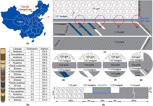
Sima Coal Mine, located in Changzhi, Shanxi, was established and commenced operations in 2006. After nearly a decade of mining, the available resources in the mine have gradually diminished. The surrounding area of the mine consists of densely populated villages and buildings. The coal deposits beneath these structures, water bodies, and railways amount to approximately 80 million tons, with a significant portion being high-quality coking coal. To maximize coal recovery and enhance resource extraction rates, the mine proposed the utilization of the paste filling method for the first time, conducting an experiment on the 1116 panel.
The 1116 panel is adjacent to the 1101 panel, with a coal pillar separating them, measuring 10 meters in width. No villages or buildings exist above the 1101 panel, and therefore, the caving method was employed. The roadways in the 1116 panel were designed in a "W" shape, consisting of two headgates, one tailgate, and two crosscuts. The 3# coal, located at a depth of 250 m, possesses a thickness of 6.5 m. The 1116 panel has a strike length of 900 m and a dip length of 205 m. The mining and backfilling process for each branch roadway typically takes approximately 28 days. The mine location and working face layout are illustrated in .
Figure 1. Position of mine and layout of working face: (a) test site position; (b) borehole column diagram of working face; (c) layout of working face; and (h) A-a side.
2.2. Roadway support
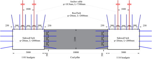
Both the 1101 and 1116 headgates have rectangular cross-sections with dimensions of 5.0 × 3.2 m (width × height) and are supported using anchor cables and bolts.
The roof is supported by φ 20 × 2400 mm bolts with a spacing of 900 × 1000 mm, anchored with 1 MSCKb2360 and 1 MSZ2360. The roof is also reinforced by φ 18.9 × 7300 mm anchor cables with a spacing of 1800 × 2000 mm, anchored with 1 MSCKb2360 and 2 MSZ2360. Additionally, both sides are supported by φ 20 × 2000 mm bolts with a spacing of 800 × 1000 mm, anchored with 1 MSCKb2360 and 1 MSZ2360. The roadway support section is depicted in .
Figure 2. The support section of roadway.
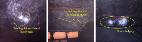
2.3. On-site observations
presents on-site images of 1116 headgate, illustrating significant deformation and subsidence in the roof area. Many ladder beams are bent and deformed, and a pronounced bulge is observed in the upper part of the coal pillar rib. Furthermore, there are also a large number of bolts and anchor cables with high loads on site, and there is a phenomenon of significant bulging of the bottom plate of the roadway in localized areas. These deformations primarily resulted from lateral support stresses.
Figure 3. Deformation on site.
3. Analysis of roadway stability factors
The stability of 1116 headgate in Sima Coal Mine is influenced by the mining of two working faces. The 1101 panel is mined using the caving method, resulting in substantial mining-induced effects. The hard rock strata situated above the gob tend to form an overhanging roof, imposing significant pressure on both 1116 headgate and coal pillar. The 1116 panel is mined using the CMCB method, where coal pillars and filling materials are loaded alternately, leading to local stress concentration.
3.1. Overhanging roof of 1101 panel
There is a hard roof above 1101 panel in Sima Coal mine, which is high-strength and good integrity. Hard roof is difficult to collapse in time after mining at working face, resulting in hard overhanging roof at the side of coal pillar. Failure of the overhanging roof to collapse in time is prone to fracture, and different fracture locations will affect the stability of gob-side roadway to different degrees (Yang et al. Citation2019a; Chen et al. Citation2022).
According to masonry beam theory (Qian et al. Citation1994), after mining 1101 panel, the hard rock strata above the gob cracks and forms a tidy block structure, and the adjacent blocks are hinged by horizontal thrust (Liu et al. Citation2017; Zhang et al. Citation2020). After mining of 1101 panel, there are three possible fracture locations in the main roof, which are side of gob, above coal pillar and above 1116 headgate. The fracture results of roof are shown in .
Figure 4. The fracture structure of main roof.
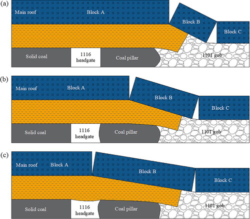
When the main roof fractures at the side of 1101 gob, block A remains intact with a partial overhanging roof above the gob. Since the length of overhanging roof of block A is not substantial and the subsidence is minimal, the stress within the coal pillar does not increase significantly, resulting in a favorable stress environment for 1116 headgate.
When the main roof fractures above coal pillar, coal pillar not only experiences vertical loads caused by bending subsidence in block A but also encounters double vertical and horizontal loads due to the rotational subsidence of fractured block B. The stress concentration leads to significant deformations of the coal pillar, making it prone to instability.
When the main roof fractures above 1116 headgate, the roof above the headgate is subjected to the loading of blocks A and B. If the overhead load exceeds the bearing limit, it can cause fractures in the immediate roof. The coal pillar is entirely pressed beneath the fractured block B, resulting in a significant reduction in its bearing capacity.
In summary, the location of fractures in the hard roof plays a crucial role of the gob-side roadway. Employing roof-cutting pressure relief methods can optimize the roof structure.
3.2. Mining 1116 panel by using CMCB
CMCB is a mining method characterized by intermittent mining and step-by-step coal replacement using backfilling. It offers advantages such as minimal disturbance and low roof subsidence (Ma et al. Citation2019). illustrates the four-step mining mode employed in the 1116 panel, where the working face is mined in four stages. Each branch roadway is filled immediately after mining, and the next branch roadway is mined simultaneously, allowing for simultaneous working without interference. After the first filling body reaches stability, the second, third, and fourth stage coal pillars are successively mined, achieving the goal of CMCB and full mining with full filling. It is worth mentioning that the scheme of alternating excavation and backfilling helps to minimize the deformation of the overlying layers due to the compressibility of the backfill material (Skrzypkowski Citation2021).
Figure 5. The mining way of CMCB.
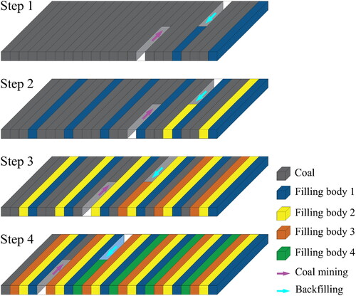
During the CMCB process, the roof undergoes three stages: coal pillar support, joint support of the coal pillar and filling body, and filling body support. These stages subject the roadway to multiple mining impacts, resulting in constantly changing interaction mechanisms between the coal pillar and filling body and complex and variable stress distributions.
3.3. Bearing characteristics of filling materials
The filling materials selected for CMCB mainly consist of gangue, cement, fly ash, water and additives, among which gangue is used as skeleton, cement as cementing material and fly ash as admixture, and additives are used to improve the parameters of filling materials.
Waste rocks discharged from Sima Coal mine during excavating, mining and coal washing are selected as gangue, and the main components are SiO2, Al2O3, and CaO, etc. In order to meet the smoothness of transportation of filling materials, the particle size of gangue after crushing should not exceed 15 mm, and the proportion of 0 ∼ 5 mm should reach more than 50%.
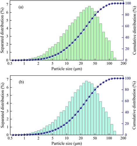
The particle size distribution characteristics of filling materials are shown in . Cement selects ordinary 42.5 Portland cement, and the maximum particle size is not more than 150 µm, of which the particle size below 27.5 µm accounts for more than 50%. The main components of fly ash are SiO2, Al2O3, FeO, CaO, rich in O, Si, Ca, Al, Fe, and other elements, and the particle size is mainly concentrated in 5 ∼ 100 µm.
Figure 6. The particle distribution of filling materials: (a) fly ash; (b) cement.
The filling materials used in CMCB, not only needs to have good fluidity, but also needs to have certain strength. In the view of this, as shown in , the influences of cement, fly ash and slurry concentration on the age strength were studied, respectively.
Figure 7. The age strength of filling body.
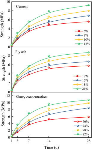
demonstrates that the changing rule of age strength at different proportions was basically consistent. The 1 ∼ 7 d was rapid growth stage, the 7 ∼ 14 d was slow growth stage, and the 14 ∼ 28 d was stable growth stage. When the cement dosage increased from 6% to 12%, the 28 d strength increased from 5.6 MPa to 9.2 MPa. When fly ash dosage increased from 12% to 21%, the 28 d strength increased from 5.8 MPa to 8.7 MPa. When the slurry concentration increased from 70% to 82%, the 28 d strength increased from 5.9 MPa to 10.8 MPa.
Generally, the strength of filling body in CMCB is required to reach 3 ∼ 5 MPa (Li et al. Citation2022b). According to the above research results, it can basically meet the requirements at 7 d. Through comprehensive consideration of material fluidity, strength, site geological conditions and other factors, finally, the ratio of gangue to fly ash to cement were determined to be 5:2:1, slurry concentration was 74%∼78%.
4. The numerical simulation analysis of gob-side roadway
4.1. Simulation scheme
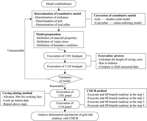
shows the specific simulation process. (1) constitutive models and mechanical parameters of rock strata, gob and coal pillar were determined and corrected, respectively; (2) ground stress and boundary conditions were imposed; (3) 1101 headgate and 1116 headgate were excavated, and the simulation results were compared with field measurements to prove that overall model was rational; (4) 1101 panel was mined with the full height method; (5) CMCB was adopted to mine 1116 headgate.
Figure 8. The process of numerical simulation.
depicts the establishment of the FLAC3D numerical calculation model based on the actual site conditions. The model dimensions were set to 280 × 400 × 62.1 m, consisting of 1,541,120 units and 1,597,425 nodes. The model boundaries were fixed at the bottom and sides, while a 6.3 MPa vertical stress was applied to the top. To accurately simulate the behavior of different rock formations, various constitutive models were employed. The gob was simulated using the double-yield model, while the coal pillar and other rock strata were modeled using the strain-softening model and Mohr-Coulomb model, respectively. The mechanical parameters of each rock stratum are presented in .
Figure 9. Numerical calculation model.
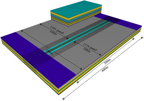
Table 1. The mechanical parameters of model.
4.2. The characteristics of rock strata of roof
The height of the caving zone after mining 1101 panel was determined using an empirical formula established by M et al. (Citation1995). This formula, which has been widely applied in various mines, provides an estimate of the caving zone height (Yavuz Citation2004; Tajdus Citation2009).
(1)
(1)
In this formula: is the height of caving zone;
is the mining height of coal;
and
are modification factor (Chen et al. Citation2023). shows the parameter value.
Table 2. Calculation coefficient of average height of caving zone.
Based on the given information, with a mining height of 6.5 m and the presence of multiple layers of hard fine sandstone and siltstone with an average strength exceeding 40 MPa. By selecting appropriate parameters from , we can determine the height of caving zone to be 21.9 m.
4.3. Verification of double-yield model
4.3.1. Mechanical analysis
After mining of 1101 panel, the rockmass in gob undergoes gradual compaction as a result of the collapse of the overlying rock strata. To accurately simulate this behavior in the numerical simulation, it is important to consider the strain-hardening of the rockmass in the gob. The stress-strain relationship of the rockmass can be described using the Salamon theoretical model, as proposed by Zhang et al. (Citation2018).
(2)
(2)
In the formula (2): is the vertical stress of rockmass of gob;
is the strain of rockmass of gob under vertical stress;
is the initial modulus of rockmass of gob, which can be calculated by formula (3):
(3)
(3)
In the formula (4): is the expansion coefficient of rockmass of gob;
is the maximum strain of rockmass of gob.
(4)
(4)
(5)
(5)
In the formula (5): is the compressive strength of caving rockmass.
According to laboratory test, the average compressive strength of roof strata is 45 MPa. Through plugging in above formulas, the expansion coefficient of the rock mass in the gob is 1.297, the maximum strain is 0.229, and the initial modulus is 74.067 GPa. The stress-strain relationship of rockmass in gob is shown in .
Table 3. Stress-strain Relationship of gob materials.
4.3.2. The correction of numerical simulation parameters
The double-yield model incorporated into FLAC3D has been found to accurately depict the gradual recovery process of rock mass stress in the gob, as demonstrated by Zhang et al. (Citation2015).
After the mining of the coal, the rockmass in the gob undergoes a process of collapse followed by gradual compaction, experiencing continuous changes in stress and deformation (Chen et al. Citation2024). The double-yield model can more accurately describe the nonlinear behavior of rockmass and the stress recovery process. Additionally, parameters of the double-yield model can be adjusted according to specific conditions to adapt to different geological conditions.
In order to validate and refine the model, a smaller-scale FLAC3D model with dimensions of 1 × 1 × 1 m was created. The model was constrained at the bottom and around its perimeter to prevent displacement, while a vertical load of 10−5 m/step was applied at the top to mimic the actual loading conditions. The model parameters were continuously adjusted to achieve convergence and improve the agreement between the numerical results and theoretical calculations.
The corrected stress-strain curve of the numerical model demonstrated good correspondence with the theoretical calculations, as depicted in . The finalized parameters are provided in .
Figure 10. Results comparison between salamon model and numerical calculation.
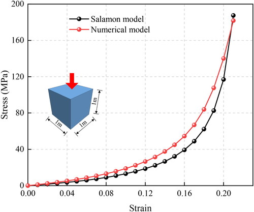
Table 4. The mechanical parameters of materials in gob.
4.3.3. The verification of stress environment
To verify the rationality of the stress environment, the double-yield model was employed to simulate the 1101 panel and the rock strata in the overlying caving zone. The model was run until a state of equilibrium was achieved. Measuring points were strategically placed along the strike of the 1101 panel to capture the stress distribution. The results of these measurements are illustrated in .
Figure 11. Vertical stress distribution of 1101 gob.
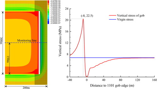
It was observed that the stress in the gob of the 1101 panel gradually recovered as the rock mass underwent compaction. At a distance of 130 m from the edge of gob, the vertical stress had recovered to 6.71 MPa, which corresponds to 98.7% of the virgin stress. Notably, a stress concentration was detected at a location approximately 8.0 m away from the 1101 panel. The maximum stress recorded in this area reached 22.5 MPa, resulting in a stress concentration coefficient of 3.31.
4.4. The correction of strain-softening model
Coal pillar can be divided into three zones: elastic, yield deformation and failure zone (Jaiswal and Shrivastva Citation2009). To capture the progressive failure process of coal pillar, the strain-softening model, was incorporated into the FLAC3D simulation(Li et al. Citation2015a).
The strain-softening model is a mathematical model used to describe the strain-softening behavior of materials during loading. The design purpose of such models is to capture the nonlinear, non-elastic, and failure behavior of materials, especially when the strength of the material decreases as the strain increases. In FLAC3D software, to achieve the gradual decrease in material strength with its own deformation, the built-in strain-softening constitutive model can be used. In combination with fish language, parameters such as cohesive strength and internal friction angle can be defined autonomously as functions of strain.
The model was established in FLAC3D, whose height was 46.5 m and the mesh size was all 0.5 × 0.5 m. The displacement of bottom and surrounding of the model were fixed, and a constant displacement of 1 × 10⁻⁵ m/step was applied to the top and bottom for loading. By changing the width of coal pillar, the load bearing conditions of coal pillar with different width-height ratios were simulated. shows the numerical model, and shows mechanical parameters of the model. When the coal pillar strain reached 1%, the cohesion decreased to 40% and the friction angle decreased by 8°.
Figure 12. Strain-softening model correction: (a) numerical calculation model; (b) stress-strain curves of coal pillar with different width-height ratios; and (c) comparison of stress peaks with different width-height ratios.
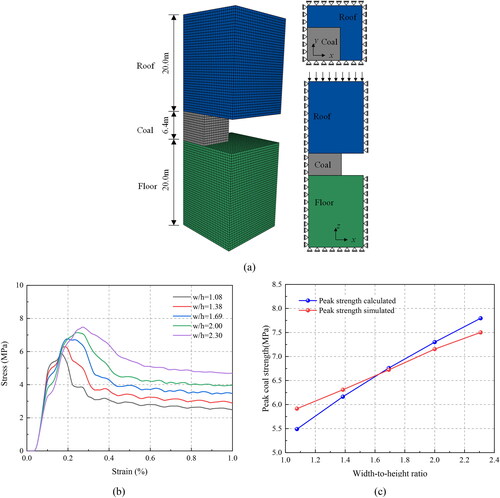
Table 5. The strain-softening model parameters of coal pillar materials.
The formula of rectangular coal pillar strength proposed by Smd and Ma (Citation1967) has been widely used in the world.
(6)
(6)
In the formula (6): is the strength of coal pillar;
is the width of coal pillar;
is the height of coal pillar.
illustrates that the width-height ratios examined were 1.08, 1.38, 1.69, 2.00, and 2.30, which corresponded to peak strengths of 5.91, 6.30, 6.72, 7.15, and 7.50 MPa, respectively. These values represent the maximum strength that the coal pillar can sustain before undergoing failure.
In , a comparison between the numerical simulation results and theoretical calculation results is presented. The high consistency observed between the two sets of results demonstrates the reasonable nature of the parameters used in the strain-softening model. This indicates that the model accurately captures the progressive failure behavior of the yielding coal pillar under different width-height ratios.
4.5. The validation of global model
The rationality of the numerical model was assessed by comparing the internal stress distribution of coal pillar with field measurements. To accomplish this, a series of stress sensors were installed at regular intervals of 1.0 m along a vertical hole drilled from 1116 headgate into the internal coal pillar. These sensors were utilized to monitor the stress levels within the coal pillar. Simultaneously, based on the numerical model in , the excavation of the 1116 headgate was conducted, and the coal pillar material was assigned as a strain-softening model. The simulation was run until equilibrium was reached, and stress values in the middle of the coal pillar were monitored in the model.
The stress sensor used on-site is the GYW80 intrinsically safe surrounding rock stress sensor for mining. The physical representation is depicted in .
Figure 13. The validation of global model: (a) GYW80 intrinsically safe surrounding rock stress sensor for mining; (b) the layout of field measured points; and (c) comparison between numerical simulation and field measured results.
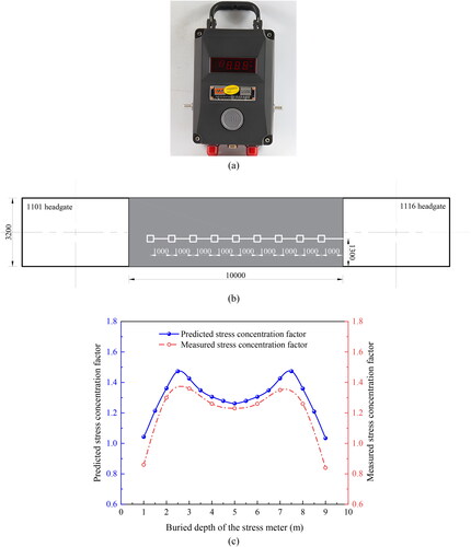
Based on the on-site monitoring results and numerical simulation outcomes, the stress concentration factors at various positions within the coal pillar are computed.
(6)
(6)
where
is predicted stress concentration factor.
is virgin stress.
is the stress value at point
illustrates the layout of the stress sensors in the field, while presents the corresponding monitoring results. It can be observed that the differences between the field-measured and numerical simulation results were minimal. Additionally, the stress distribution curves displayed a consistent trend between the two sets of data. This high level of agreement between the measured and simulated stress distributions provides strong evidence for the rationality.
5. Numerical simulation results
5.1. During mining of 1101 panel
To monitor the stress distribution of surrounding rock during mining, a measuring station was set up 150 m away from the cutting hole of the 1101 panel. Eleven measuring points were arranged inside the coal pillar and on all sides of the 1116 panel.
According to , the plastic zone of the rockmass in front of the 1101 panel exhibited an "L" shape distribution. Inside coal pillar, the plastic zone gradually increased from the front to the rear, forming a “V” shape distribution. The plastic zone of the rockmass in the 1116 panel remained relatively stable at a depth of 1–2 m.
Figure 14. Vertical stress of two ribs during the mining of 1101 panel: (a) the distribution of plastic zone in working face; (b) vertical stress curves inside coal pillar; and (c) vertical stress curves of solid coal side.
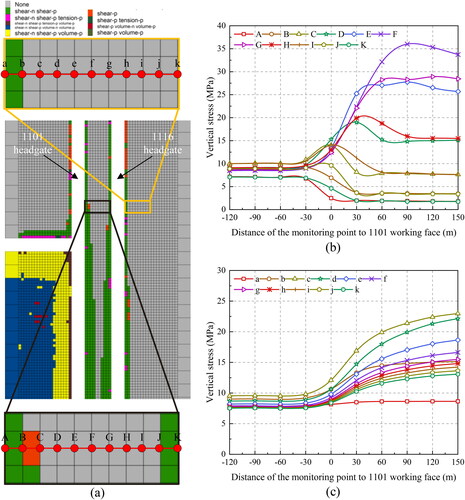
illustrates the arrangement of measuring points from surface of coal pillar to its interior, with a spacing of 1.0 m between each point. A total of 11 measuring points were utilized. The stress values at measuring points A, B, J, and K showed a decreasing trend as the working face advanced. On the other hand, points C, I, D, H, G, E, and F reached their peak stress values at distances of 0, 0, 30, 30, 60, 90, and 90 m, respectively. This indicates that the coal pillar experienced progressive failure in both the strike and dip directions.
presents the arrangement of measuring points from the surface of 1116 headgate to the deep surrounding rock of the 1116 panel, with a distance of 1.0 m between each point. Again, a total of 11 measuring points were employed. The stress values of all measuring points began to increase at a position approximately 30 m in front of the working face, indicating the influence of advance support stress disturbance. The stress values gradually increased from point a to point c and then decreased continuously from point d to the depth. This suggests that point c represents the position of peak stress.
During the gradual advancement of 1101 panel, the distribution of plastic zone and vertical stress were recorded at intervals of 30 m. The results are depicted in .
Figure 15. The plastic zone and stress distribution: (a) -120 m; (b) -90 m; (c) -60 m; (d) -30 m; (e) 0 m; (f) +30 m; (g) +60 m; (h) +90 m; (i) +120 m; and (j) +150 m.
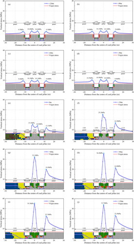
shows that the peak stress inside coal pillar was 10.0 MPa. The stress curves of 1101 panel and 1116 panel exhibited a nearly symmetrical distribution. At a distance of 2 m from roadway surface, the peak stress reached 9.5 MPa.
illustrate that as the working face advanced from −90 to −30 m, the range of plastic zone remained relatively unchanged. The peak stress of coal pillar and panels on both sides slightly increased, with the growth range being 1101 panel > coal pillar > 1116 panel.
demonstrates that as the working face reached 0 m, the peak stress inside coal pillar increased to 15.3 MPa. The stress peak on the side of the 1116 panel reached 12.1 MPa.
shows that as the working face advanced to +30 m, the internal stress of coal pillar rose sharply. The stress curve transitioned from bimodal to unimodal, and the peak stress reached 25.2 MPa, representing a 64.7% increase compared to the stress at 0 m. The peak stress on the side of the 1116 panel reached 16.9 MPa, which was 39.7% higher than at 0 m.
reveal that as the working face continued to advance, the peak stress inside coal pillar reached 36.0 MPa, while the peak stress on the side of the 1116 panel reached 22.9 MPa. By the time the working face reached +60 m, only 1 m of the plastic zone inside coal pillar remained intact. When the working face reached +90 m, the interior of coal pillar had been completely destroyed, and the plastic zone had been fully penetrated.
5.2. During the mining of 1116 panel
The mining of the 1116 panel using the CMCB method can be divided into four stages, each characterized by different stress distributions and load-bearing mechanisms. The stress distribution and migration during the mining process are illustrated in . Here is a summary of the observations for each stage:
Figure 16. Stope of stress distribution during mining 1116 panel: (a) filling 160 m in stage I; (b) filling 300 m in stage I; (c) filling 160 m in stage II; (d) filling 300 m in stage II; (e) filling 160 m in stage III; (f) filling 300 m in stage III; (g) filling 160 m in stage IV; and (h) filling 300 m in stage IV.
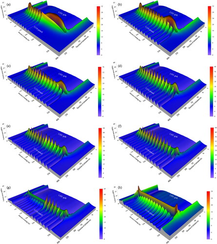
Stage I: As mining commenced, the stope roof was primarily supported by coal pillar. The stress distribution in the surrounding rock of the stope exhibited a wavy pattern. By the time the filling reached to 300 m, the maximum stress in coal pillar was 30.3 MPa, while the peak value of the advanced supporting stress was 25.8 MPa.
Stage II: The stope roof gradually transitioned from being supported by coal pillar to a joint load carried by coal pillar and filling body. When filling reached 300 m, the maximum stress in coal pillar increased to 33.1 MPa, and the peak value of the advanced supporting stress rose to 36.7 MPa.
Stage III: The joint load-bearing of coal pillar and filling body for supporting the stope roof. By the time the filling reached 300 m, the maximum stress in coal pillar was 29.8 MPa, and the peak value of the advanced supporting stress reached 42.1 MPa.
Stage IV: The stope roof gradually transitioned from the joint load of coal pillar and filling body to primarily being supported by filling body alone. When the filling reached 300 m, the stope roof load was mainly carried by filling body, with the maximum stress in coal pillar was 25.6 MPa, and the peak stress in filling body was 15.5 MPa.
In summary, during the CMCB process in the 1116 panel, there exists a primary-secondary load-bearing structure where the coal pillars and the filling body alternately support the roof load, resulting in dynamic migration of stress distribution in the surrounding rock of the mining area, exhibiting a wave-like pattern. Initially, during the early stage of mining, there was an observed increase in peak stress within the surrounding rock. As the mining progressed, the reduction in width of the coal pillar supporting the stope roof led to substantial stress concentration near 1116 headgate of the coal pillar. This concentration of stress has the potential to trigger coal pillar instability and failure, leading to significant deformation of the roadway and posing considerable risks to mining safety. The relationship between coal pillar and filling body displayed a primary-secondary bearing arrangement, with the filling body assuming the role of secondary support. During the phase of joint load-bearing between coal pillar and filling body, the stress experienced by filling body was considerably lower in comparison to that endured by coal pillar. This disparity indicates that the primary load-bearing responsibility in the stope rested with the coal pillar. Upon the completion of stage IV, all coal pillars within 1116 panel were extracted, and the primary load-bearing role transitioned to filling body. Subsequently, following the completion of the CMCB method, a significant reduction in stress within the surrounding rock was observed.
6. The industrial test
6.1. The roadway control technology
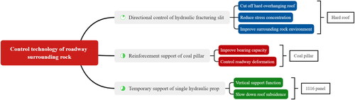
Based on the theory and numerical simulation analysis results, as well as the specific conditions of Sima Coal Mine, a control system for the roadway surrounding rock was formulated. The core of this control system is based on three key components: "directional control of hydraulic fracturing slit + reinforcement support of coal pillar + temporary support of single hydraulic prop". The control system aims to reduce stress concentration and enhance the safety of roadway. The specific measures involved in the control system are as follows:
Directional control of hydraulic fracturing slit: By strategically creating hydraulic fracturing slits in the overhanging roof above the gob in the 1101 panel, the hard and unstable roof strata can be controlled. The direction and position of the hydraulic fracturing slits are carefully planned to alleviate stress concentration and minimize the potential for roof instability and rock failure.
Reinforcement support of coal pillar: This can be achieved through various means, such as installing additional bolts and cables, using shotcrete or steel mesh for reinforcement, and employing rock bolting techniques. Reinforcing the coal pillar helps distribute the load more effectively and reduces stress concentration points.
Temporary support of single hydraulic prop: To provide immediate support during the mining process, single hydraulic props can be employed as temporary supports. These props are adjustable and can be strategically placed in critical areas to help maintain stability and reduce stress concentration. They provide localized support while allowing for flexibility and adjustability as the mining progresses.
By implementing this control system, it is expected that stress concentration inside the coal pillar can be mitigated, reducing the risk of instability and failure. The combined effect of directional control of hydraulic fracturing slits, reinforcement support of coal pillar, and temporary support of single hydraulic props helps enhance the overall safety and stability of the roadway in 1116 headgate area ().
Figure 17. The control system of roadway surrounding rock.
6.1.1. Directional control of hydraulic fracturing slit
shows the construction scheme of drilling hydraulic fracturing. The fracturing bed was a fine-grained sandstone above the roof with a thickness of 6.5 m. The estimated hydraulic fracturing length range was 240 m, and a total of 20 drilling groups were designed. Each group contained one A and a one B fracturing hole. The spacing of the two holes in the same group was 4 m, and the spacing of each group was 12 m.
Figure 18. The construction scheme of drilling hydraulic fracturing: (a) plane graph; (b) cross-section graph.
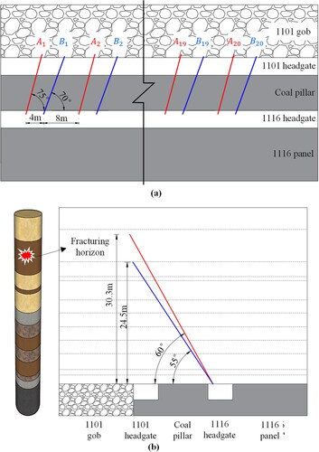
A drilling hole: in the roadway roof, the vertical elevation angle of 60° and the horizontal azimuths angle of 75° were used to drill holes in the direction of the gob of 1101 panel. The diameter of drilling hole was φ65 mm, whose depth was designed to be 35 m. And the drilling holes were fractured four times with a spacing of 5 m.
B drilling hole: in the roadway roof, the vertical elevation angle of 55° and the horizontal azimuths angle of 70° were used to drill holes in the direction of the gob of 1101 panel. The diameter of drilling hole was φ65 mm, whose depth was designed to be 30 m. And the drilling holes were fractured three times with a spacing of 5 m.
6.1.2. Reinforcement support of coal pillar
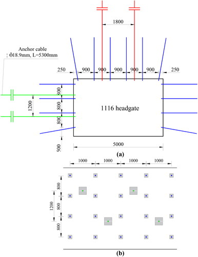
illustrates the reinforcement support configuration where two anchor cables were installed at coal pillar rib. The anchor cables utilized had a size of φ 18.9 × 5300 mm. They were arranged in rows with a spacing of 1200 mm horizontally and 1000 mm vertically. The arrangement followed an up and down dislocation layout, ensuring comprehensive reinforcement coverage in the supported area.
Figure 19. Anchor cable reinforcement support: (a) cross-section graph and (b) side view.
6.1.3. The temporary support of single hydraulic prop
The single hydraulic prop serves as a vital temporary support technology employed in coal mining operations to provide roof support and ensure stability in gob areas. As a commonly used temporary support device, it offers the flexibility to adjust the telescopic extension length of the hydraulic cylinder, enabling attachment of the prop to either the roof or coal wall as needed ().
Figure 20. The temporary support of single hydraulic prop.
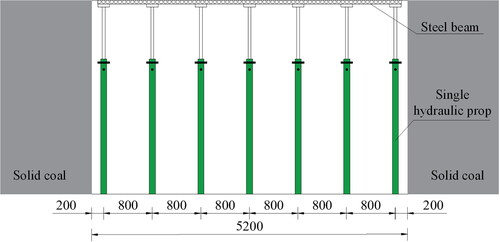
Following the excavation of the branch roadway in 1116 panel, a gob area is formed. To mitigate the risks associated with gob collapse and roof caving resulting from coal seam mining, prompt implementation of temporary support measures is crucial along the side adjacent to the working face of 1116 headgate. It is important to note that the single hydraulic prop should not be removed prematurely after gob filling. Instead, its removal should be carried out once the backfilling material has attained the expected strength, ensuring the stability and integrity of the supported area.
6.2. The roadway control effect
The convergences of the roof, yield pillar rib, solid coal rib and floor of roadway were monitored. shows the monitoring results.
Figure 21. The convergences of roadway.
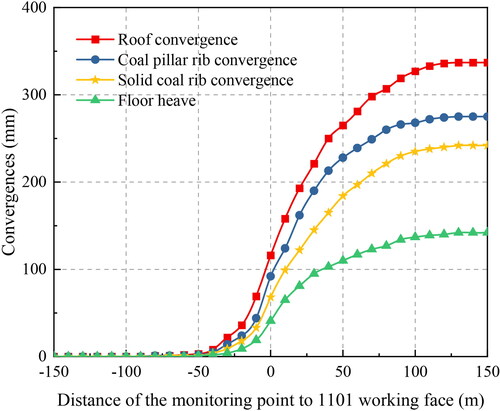
The symbol "-" in the figure indicates that the monitoring station is located in front of the working face, while the symbol "+" indicates that the monitoring station is located behind the working face.
When the monitoring station is positioned more than 50 m in front of the working face, the roadway basically does not deform. Starting from a location 50 m ahead of the advancing working face, the roadway begins to be affected by the advance mining activities, and as the working face approaches, the rate of surrounding rock deformation gradually increases. When the monitoring station is positioned 110 m behind the working face, the surrounding rock stabilizes, and deformation ceases. Ultimately, after stabilization, the maximum convergence of the roof, coal pillar rib, solid coal rib and floor were 337, 275, 242, and 142 mm, respectively.
7. Conclusion
This study investigated the stability characteristics of gob-side roadway using the CMCB method through a combination of on-site observations and numerical simulations. The following conclusions were drawn:
Gob-side roadway, although helpful in alleviating mining tension, is influenced by mining activities on both sides of the working face. In particular, the 1101 panel was prone to forming a hard overhanging roof. The mining process of the 1116 panel involved alternating loading between the coal pillar and filling body, resulting in multiple stress distribution migrations. The complex and changing stress environment of the gob-side roadway made it challenging to analyze using theoretical approaches.
To ensure the accuracy of the numerical simulations, the constitutive model, mechanical parameters, and other relevant parameters were meticulously calibrated. The simulation results revealed that during the caving mining of the 1101 panel, significant stress concentration occurred in the surrounding rock of the coal pillar, with a maximum stress concentration factor of 5.29. During the CMCB mining of the 1116 panel, the stress distribution in the stope exhibited dynamic migration, and the surrounding rock was influenced by both lateral supporting stress and advanced mining stress, resulting in a maximum stress concentration coefficient of 6.62.
During the mining process of the 1116 panel, coal pillars with gradually diminishing width are formed within the working face. At the completion of the first, second, third, and fourth mining steps, the widths of the coal pillars are 15, 10, 5, and 0 m, respectively. During the first three steps, the peak stresses within the coal pillar are measured at 25.8, 36.7, and 42.1 MPa, respectively. Subsequent to the completion of the fourth mining step, the load on the roof of the working face is predominantly borne by the filling body, with a peak stress within the filling body of 15.5 MPa.
To improve the stress environment of surrounding rock, a roadway support technology was proposed. Field monitoring demonstrated that during the mining of 1101 panel, the maximum convergence of the roof, coal pillar rib, solid coal rib and floor were 337, 275, 242 and 142 mm, respectively. The technology could contribute to the understanding and practical implementation of mining methods in similar geological conditions.
Future research could explore the long-term performance and optimization of the proposed control system for roadway surrounding rock in CMCB mining operations. Additionally, research could delve into the development of advanced numerical models and monitoring techniques tailored specifically to the unique challenges of CMCB mining, allowing for more accurate prediction and management of roadway stability. Furthermore, exploration of innovative materials and technologies for reinforcement and support in CMCB mining environments could provide valuable insights into enhancing safety and efficiency.
Data availability statement
Data will be made available on request.
Disclosure statement
The authors declared that they have no conflicts of interest to this work.
Additional information
Funding
References
- Ajayi SA, Ma L, Spearing AJS. 2022. Ground stress analysis and automation of workface in continuous mining continuous backfill operation. Minerals. 12(6):754. doi: 10.3390/min12060754.
- Babets D, Sdvyzhkova O, Hapieiev S, Shashenko O, Vasyl V. 2023. Multifactorial analysis of a gateroad stability at goaf interface during longwall coal mining: A case study. Min Miner Depos. 17(2):9–19. doi: 10.33271/mining17.02.009.
- Bai J, Shen W, Guo G, Wang X, Yu Y. 2015. Roof deformation, failure characteristics, and preventive techniques of gob-side entry driving heading adjacent to the advancing working face. Rock Mech Rock Eng. 48(6):2447–2458. doi: 10.1007/s00603-015-0713-2.
- Bai Q, Tu S, Wang F, Zhang C. 2017. Field and numerical investigations of gateroad system failure induced by hard roofs in a longwall top coal caving face. Int J Coal Geol. 173:176–199. doi: 10.1016/j.coal.2017.02.015.
- Cao Z, Xu P, Li Z, Zhang M, Zhao Y, Shen W. 2018. Joint bearing mechanism of coal pillar and backfilling body in roadway backfilling mining technology. CMC-Comp Mater Continua. 54:137–159.
- Chen D, Wang X, Wu S, Zhang F, Fan Z, Wang X, Li M. 2023. Study on stability mechanism and control techniques of surrounding rock in gob-side entry retaining with flexible formwork concrete wall. J Cent South Univ. 30(9):2966–2982. doi: 10.1007/s11771-023-5436-z.
- Chen D, Wang X, Zhang F, Bai J, Zhao X, Li M, Yu Y, Wang X, Sun S. 2024. Study on the mechanism of progressive instability of special-shaped coal pillar and the stability control of roadway under the influence of mining. Rock Mech Rock Eng. doi: 10.1007/s00603-024-03798-6.
- Chen D, Wang X, Zhang F, Li M, Zhao X, Li G, Yu Y, Wang G, Zhao J, Wang X. 2022. Research on directional controllability of cracking in hydraulic fracturing of hard overburden based on local stress field intervention. Energies. 15(12):4252. doi: 10.3390/en15124252.
- Feng X, Zhang N, Gong L, Xue F, Zheng X. 2015. Application of a backfilling method in coal mining to realise an ecologically sensitive “black gold” industry. Energies. 8(5):3628–3639. doi: 10.3390/en8053628.
- Gao F, Stead D, Kang H. 2015. Numerical simulation of squeezing failure in a coal mine roadway due to mining-induced stresses. Rock Mech Rock Eng. 48(4):1635–1645. doi: 10.1007/s00603-014-0653-2.
- Hu B, Liu P, Cui F, Wang H 2020. Review and development status of backfill coal mining technology in China. Coal Science and Technology. 48:39-47.
- Huang W, Liu S, Gao M, Hou T, Wang X, Zhao T, Sui L, Xie Z. 2022. Improvement of reinforcement performance and engineering application of small coal pillars arranged in double roadways. Sustainability. 15(1):292. doi: 10.3390/su15010292.
- Huang B, Liu J, Zhang Q. 2018. The reasonable breaking location of overhanging hard roof for directional hydraulic fracturing to control strong strata behaviors of gob-side entry. Int J Rock Mech Min Sci. 103:1–11. doi: 10.1016/j.ijrmms.2018.01.013.
- Jaiswal A, Shrivastva BK. 2009. Numerical simulation of coal pillar strength. Int J Rock Mech Min Sci. 46(4):779–788. doi: 10.1016/j.ijrmms.2008.11.003.
- Jia Y, Wang Y, Zhuo R, Lou F, Jin S, Zhao P. 2022. Research on the safety control technology of gob-side entry in inclined thick coal seam. Process Safety and Environmental Protection. 166:241–248. doi: 10.1016/j.psep.2022.08.019.
- Kang H, Lv H, Gao F, Meng X, Feng Y. 2018. Understanding mechanisms of destressing mining-induced stresses using hydraulic fracturing. Int J Coal Geol. 196:19–28. doi: 10.1016/j.coal.2018.06.023.
- Le Q, Vladimir Z, Thang PD. 2020. Design a reasonable width of coal pillar using a numerical model. A case study of Khe Cham basin, Vietnam. In E3S web of conferences.
- Li W, Bai J, Peng S, Wang X, Xu Y. 2015a. Numerical modeling for yield pillar design: a case study. Rock Mech Rock Eng. 48(1):305–318. doi: 10.1007/s00603-013-0539-8.
- Li Z, Dou L, Wang G, Cai W, He J, Ding Y. 2015b. Risk evaluation of rock burst through theory of static and dynamic stresses superposition. J Cent South Univ. 22(2):676–683. doi: 10.1007/s11771-015-2570-2.
- Li Y, Lu B, Yang R, Lin H, Xu B, Wang S, Liu C. 2022a. Cemented backfilling mining technology with continuous mining and continuous backfilling method for underground coal mine and typical engineering cases. J China Coal Society. 47:1055–1071.
- Li Y, Lu B, Yang R, Lin H, Xu B, Wang S, Liu C. 2022b. Risk evaluation of rock burst through theory of static and dynamic stresses superposition. J China Coal Society. 47:1055–1071.
- Lin H, Yang R, Li Y, Lu B, Xu B, Fan Z, Li J. 2022. Application of short-wall continuous mining and continuous backfilling cemented-fill mining technology. Chinese Journal of Engineering. 44:981-992.
- Lin H, Yang R, Lu B, Li Y, Fang S, Fan Z, Li Z. 2021. Overlying strata movement law of continuous mining and continuous backfilling cemented-fill mining. Environ Earth Sci. 80(20). doi: 10.1007/s12665-021-09993-w.
- Liu C, Li H, Mitri H, Jiang D, Li H, Feng J. 2017. Voussoir beam model for lower strong roof strata movement in longwall mining: case study. J Rock Mech Geotech Eng. 9(6):1171–1176. doi: 10.1016/j.jrmge.2017.07.002.
- Liu J, Liu C, Yao Q, Si G. 2020. The position of hydraulic fracturing to initiate vertical fractures in hard hanging roof for stress relief. Int J Rock Mech Min Sci. 132:104328. doi: 10.1016/j.ijrmms.2020.104328.
- Liu H, Zhang B, Li X, Liu C, Wang C, Wang F, Chen D. 2022. Research on roof damage mechanism and control technology of gob-side entry retaining under close distance gob. Eng Fail Anal. 138:106331. doi: 10.1016/j.engfailanal.2022.106331.
- Lu B, Li Y, Fang S, Lin H, Zhu Y. 2021. Cemented backfilling mining technology for gently inclined coal seams using a continuous mining and continuous backfilling method. Shock Vib. 2021:1–12. doi: 10.1155/2021/6652309.
- Lv J, Wan Z, Zhang Y, Wang J, Yan W, Xiong L. 2022. Effect of multi-factor dynamic loading on gob-side entry driving during longwall face extraction: a case study. Bull Eng Geol Environ. 81(10):409. doi: 10.1007/s10064-022-02880-z.
- M B, F K, V RD. 1995. Chinese and North American high-extraction underground coal mining strata behavior and water protection experience and guidelines. Conference presented at.
- Ma L, Jin Z, Liu W, Zhang D, Zhang Y. 2019. Wongawilli roadway backfilling coal mining method: a case study in Wangtaipu coal mine. IJOGCT. 20(3):342–359. doi: 10.1504/IJOGCT.2019.098457.
- Malashkevych D, Petlovanyi M, Sai K, Zubko S. 2022. Research into the coal quality with a new selective mining technology of the waste rock accumulation in the mined-out area. Min Miner Depos. 16(4):103–114. doi: 10.33271/mining16.04.103.
- Orlecka-Sikora B. 2010. The role of static stress transfer in mining induced seismic events occurrence, a case study of the Rudna mine in the Legnica-Glogow Copper District in Poland. Geophysical Journal International. 182(2):1087–1095. doi: 10.1111/j.1365-246X.2010.04672.x.
- Qian M, Miao X, He F. 1994. Analysis of key block in the structure of Voussoir beam in longwall mining. Journal of China Coal Society. 557-563.
- Seryakov VM, Rib SV, Basov VV, Fryanov VN. 2018. Geomechanical substantiation of technology parameters for coal mining in interaction zone of longwall face and gate roadway. J Min Sci. 54(6):899–906. doi: 10.1134/S1062739118065047.
- Skrzypkowski K. 2020a. Comparative analysis of the mining cribs models filled with gangue. Energies. 13(20):5290. doi: 10.3390/en13205290.
- Skrzypkowski K. 2020b. Decreasing mining losses for the room and pillar method by replacing the inter-room pillars by the construction of wooden cribs filled with waste rocks. Energies. 13(14):3564. doi: 10.3390/en13143564.
- Skrzypkowski K. 2021. 3D numerical modelling of the application of cemented paste backfill on displacements around strip excavations. Energies. 14(22):7750. doi: 10.3390/en14227750.
- Smd G, Ma H. 1967. A study of the strength of coal pillars. Journal of the South African Institute of Mining & Metallurgy. 68.
- Smoliński A, Malashkevych D, Petlovanyi M, Rysbekov K, Lozynskyi V, Sai K. 2022. Research into impact of leaving waste rocks in the mined-out space on the geomechanical state of the rock mass surrounding the longwall face. Energies. 15(24):9522. doi: 10.3390/en15249522.
- Tajdus K. 2009. New method for determining the elastic parameters of rock mass layers in the region of underground mining influence. Int J Rock Mech Min Sci. 46:1296–1305.
- Wen X, Ge Z, Zhang F. 2022. Study on the migration law of overlying rock in the upward layered continuous mining face of thick coal seam with paste backfill mining. Math Prob Eng. 2022:1–12. doi: 10.1155/2022/7297477.
- Xia Z, Yao Q, Meng G, Xu Q, Tang C, Zhu L, Wang W, Shen Q. 2021. Numerical study of stability of mining roadways with 6.0-m section coal pillars under influence of repeated mining. Int J Rock Mech Min Sci. 138:104641. doi: 10.1016/j.ijrmms.2021.104641.
- Xie H, Gao M, Zhang R, Peng G, Wang W, Li A. 2019. Study on the mechanical properties and mechanical response of coal mining at 1000m or deeper. Rock Mech Rock Eng. 52(5):1475–1490. doi: 10.1007/s00603-018-1509-y.
- Xu B, Yue Z, Li Y, Wang S, Li J, Lu B. 2022. Research on the control of overburden deformation by filling ratio of cementing filling method with continuous mining and continuous backfilling. Environ Sci Pollut Res. 30(10):26764–26777. doi: 10.1007/s11356-022-24038-w.
- Xue Y, Cao Z, Du F, Zhu L. 2018. The influence of the backfilling roadway driving sequence on the rockburst risk of a coal pillar based on an energy density criterion. Sustainability. 10(8):2609. doi: 10.3390/su10082609.
- Yang X, Hu C, He M, Wang H, Zhou Y, Liu X, Zhen E, Ma X. 2019. Study on presplitting blasting the roof strata of adjacent roadway to control roadway deformation. Shock Vib. 2019:1–16. doi: 10.1155/2019/3174898.
- Yang J, Wang H, Wang Y, Liu B, Hou S, Cheng Y. 2019. Stability analysis of the entry in a new mining approach influenced by roof fracture position. Sustainability. 11(22):6349. doi: 10.3390/su11226349.
- Yavuz H. 2004. An estimation method for cover pressure re-establishment distance and pressure distribution in the goaf of longwall coal mines. Int J Rock Mech Min Sci. 41(2):193–205. doi: 10.1016/S1365-1609(03)00082-0.
- Yu Y, Bai J, Wang X, Zhang L. 2020. Control of the surrounding rock of a goaf-side entry driving heading mining face. Sustainability. 12(7):2623. doi: 10.3390/su12072623.
- Yu Y, Lu J, Pan Y, Zhao X, Chen D. 2021. Research and practice on filling technology of fully mechanized coal mining face through trend abandoned roadway. Sustainability. 13(17):9920. doi: 10.3390/su13179920.
- Yu Y, Ma L, Zhang D. 2019. Characteristics of roof ground subsidence while applying a continuous excavation continuous backfill method in longwall mining. Energies. 13(1):95. doi: 10.3390/en13010095.
- Zhang Z, Bai J, Chen Y, Yan S. 2015. An innovative approach for gob-side entry retaining in highly gassy fully-mechanized longwall top-coal caving. Int J Rock Mech Min Sci. 80:1–11. doi: 10.1016/j.ijrmms.2015.09.001.
- Zhang C, Jin Z, Song X, Feng G, Li Z, Gao R, Zhu D, Li C. 2020. Failure mechanism and fracture aperture characteristics of hard thick main roof based on voussoir beam structure in longwall coal mining. Energy Science & Engineering. 8(2):340–352. doi: 10.1002/ese3.492.
- Zhang G, Liang S, Tan Y, Xie F, Chen S, Jia H. 2018. Numerical modeling for longwall pillar design: a case study from a typical longwall panel in China. Journal of Geophysics and Engineering. 15(1):121–134. doi: 10.1088/1742-2140/aa9ca4.