
 ?Mathematical formulae have been encoded as MathML and are displayed in this HTML version using MathJax in order to improve their display. Uncheck the box to turn MathJax off. This feature requires Javascript. Click on a formula to zoom.
Abstract
Dump failure is one of the most catastrophic hazards in the opencast mining industry and involves sudden and violent failures. Therefore, susceptible region identification is essential for slope failure mitigation in the large dump. This study proposed a sustainable approach for large dump critical zone of interest (CZI) identification, stability monitoring and slope failure prediction. UAV close-range photogrammetry survey and structure-from-motion (SfM) approach were used for the dump realistic 3D model reconstruction. 3D numerical modelling was employed for dump stability analysis. In this investigation, the dump critical zone, slope factor of safety (FOS), displacement and slope failure prediction were analysed using the 3D numerical modelling. The results indicate that maximum displacement was found in the critical zone I. However, the dump was stable under static conditions. Dump critical slope failure time is predicted using the inverse velocity method. The results of this investigation are reliable and establish the scope of UAV photogrammetry for realistic 3D modelling. In addition, the slope stability state and failure model were consistent with field observations. The proposed approach can be used for the mine, hill, and roadcut slopes. UAV technology and 3D modelling approaches have substantially reduced data collection time and expense.
Introduction
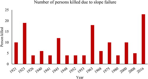
Mine slope failure is a significant issue in the opencast industry. Therefore, dump CZI and slope failure prediction are essential for human and mine machinery safety. The opencast mining method generates huge overburden (OB) material inside the mine leasehold area. The soil and rock are removed from above the coal seam, and the removed material is called OB material. OB material is loose, a mixture of soil and rock and discrete. This material accommodated inside the mine area with stability is a challenging task for mining engineers. The internal dump has a limited ground floor area for OB material accommodation. So, a steep angle dump slope with maximum height is used for the material dumping. In this study area, the dump has an average height of 100 m. The volume of OB depends on the mine stripping ratio and working depth. Drilling and blasting operations fragment the OB material, and the shovel damper combination is used for transporting and depositing at a dump site. Internal dumping is a sustainable mining approach; however, unplanned OB deposition is the leading cause of slope failure, which may be a disaster. A devastating collapse occurred on February 22nd 2023, in a coal mine in the Alxa League region of Inner Mongolia, China. The incident included the failure of a slope of 180 m in height, leading to the burial of the mine beneath a significant volume of debris. The occurrence resulted in the unfortunate death of a minimum of 6 people, with an additional 47 people being listed as missing (Open-pit coal mine collapse in China Citation2023). Many dump slope failure cases have occurred in India, as shown in (Dash Citation2019). Several dump slope collapse incidents occurred at the Basundhara mines of the Mahanadi Coalfields Limited (2013) (Kumar Behera et al. Citation2016), the Singreni mine in December 2009 (Poulsen et al. Citation2014), and the Western Coalfield Limited in Nagpur, India (Kainthola et al. Citation2011). In 2016, twenty-five people were killed in the Rajmahal opencast mine because of a dump slope collapse (Yadav et al. Citation2019). In 1986–1987, 1999–2000, 2009–2010, 2014–2015, and 2015–2016, Coal India Limited (CIL) removed 160, 462, 695, 886.528, and 1148.908 million cubic meters of OB, respectively. Coal production from opencast mining in India accounts for approximately 95.64% of overall, while underground mining accounts for only 4.36% (Vinay et al. Citation2022). According to the mine regulatory agency, dump stability analysis and monitoring are essential for ensuring human safety and smooth-running mining operations.
Figure 1. Fatality to slope failure from 1921 to 2016 in India (Dash Citation2019).
The mine dump mass is composed of loose soil and different types of sedimentary rock, such as shale and sandstone. Generally, circular failure occurs in a dump (Igwe et al. Citation2023) because the material is discrete, broken, and fragmented. Slope failure can result in serious environmental issues, capital loss, and even endanger human lives (Laurence Citation2006). Opencast mining activity continuously produces a huge OB material and continuously deposits material, thereby increasing dump height. Increasing dump height also increases the risk of slope failure.
In recent years, unmanned aerial vehicle (UAV) technology has rapidly developed (Karam et al. Citation2022; Iqbal et al. Citation2023; Li et al. Citation2023; Ollervides-Vazquez et al. Citation2023; Yordanov et al. Citation2023), and several researchers have used it to study mined-out area location, deformation, slope monitoring, etc., as well as mining influence on landslip place time evolution (Czikhardt et al. Citation2017; Yang et al. Citation2018; Chen et al. Citation2020). However, complex problems of time and space cannot be solved solely through remote sensing, and field exploration, on-site investigation, and theoretical analysis are required. Using a multiple UAV network, a machine learning model was utilised to recognise mining haul road objects (Xu et al. Citation2023).
In the past, extensive studies have been conducted on the stability of existing dumps under static, dynamic, and rainfall conditions (Koner and Chakravarty Citation2011; Citation2016; Layek et al. Citation2022), failure mechanisms (Wang and Chen Citation2017; Zhan et al. Citation2021), stability assessment (Kumar Behera et al. Citation2016), stabilisation of mine dumps (Rai et al. Citation2012; Ranjan et al. Citation2017; Rajak et al. Citation2021), Dump failure probability analysis (Kumar et al. Citation2023) and dump failure zone identification (Chand and Koner Citation2023a; Citation2023b). Failure of the dump during construction has also been reported (Poulsen et al. Citation2014). Therefore, it is an active research area in the mining industry. Some efforts have been made to investigate the factors influencing dump stability based on the FOS and slope deformation using numerical simulations (Koner Citation2021). Dump stability analysis investigation has recently focused on 3D modelling methods and UAV photogrammetry. Layek used (DJI Phantom 4 Pro) drone for the dump image data collection and 3D reconstruction of a dump (Layek et al. Citation2022). The UAV platform detects in-situ rock mass features and estimates slope stability (Junaid et al. Citation2022). Using the UAV data, a rock slope hazard map was prepared (Vemulapalli and Mesapam Citation2021).
The parameters influencing dump stability are slope angle, height, curvature, weak ground floor, and material properties. For a slope stability assessment, it is essential to have a good understanding of the geotechnical properties and design parameters of the dump. Slope stability maps are helpful tools for failure zone identification and depict the possibility of failure in a specific region (Gu et al. Citation2015). GIS tools have been used to address landslides in many studies. This approach is suitable for preparing dump stability maps. Some researchers have used qualitative, quantitative, and semi-quantitative approaches for stability mapping (Shano et al. Citation2020).
Geotechnical engineers commonly employ the 2D limit equilibrium method to evaluate slope stability. Large opencast mine dump stability analysis requires a robust approach. So that dump stability and failure zones can be identified. Recently, UAV platform applications have been widely used in landslide, slope monitoring, and bridge health monitoring. The opencast mining industry also adopts UAV technology for the entire mine, including digital elevation model creation, dump management, and mine slope monitoring. The UAV technology and numerical modelling were used for mine dump and pit slope stability analyses (Layek et al. Citation2022; Maiti and Chakravarty Citation2022) and hill slope stability analysis by Congress and Puppala Citation2021. The UAV-DP approach was implemented for geological surveys and rock slope stability evaluations (Hao et al. Citation2023).
Creating an actual ground condition realistic 3D model is challenging. Over the years, many approaches have been applied, such as light detection and ranging (LiDAR), which can be used (Jensen and Mathews Citation2016) to generate a 3D model of a location through surveying. It provides the 3D coordinates of the surveyed geometry, known as point cloud data (PCD). Nonetheless, in this study, to minimise costs, a UAV platform was used to acquire the imagery of the study area (Bar et al. Citation2020). Additionally, the use of LiDAR in active mining areas is problematic. LiDAR must be used from different locations numerous times, and it is time-consuming and challenging to place the instrument without interfering with mining activities. Therefore, the use of UAVs is appropriate, given their high-resolution images, low cost, and lack of interference with mining activities. The comparative error was less than 0.4%, which shows that the suggested reconstruction of UAV images is viable and efficient. The usability of UAVs is an effective way to map and survey opencast mine regions without interrupting mining operations.
Nowadays, computing power is becoming faster; therefore, developing a realistic 3D model with high accuracy is possible. In theory, multiple images of an exact location or object captured from different input angles can produce 3D point cloud data. PCD can be achieved using a computer-vision approach, SfM, a popular technique for creating 3D models. SfM is fast, reliable, and available in open-source code (Westoby et al. Citation2012; Schönberger and Michael Citation2016). SfM extracts and matches the features of different images and triangulates the features to extract their 3D locations. However, 3D numerical simulations of large areas remain challenging because they require extensive computation facilities.
The previous study identified a dump critical zone (Chand and Koner Citation2023a; Citation2023b). This paper aims to develop a large internal dump stability monitoring methodology. The study primarily relies on a UAV close-ranging photogrammetry survey and a 3D numerical modelling method for dump stability analysis. UAV close-range photogrammetry survey images were used for the dump PCD generation and realistic 3D model reconstruction. The 3D limit equilibrium analysis assesses the stability of the entire dump and creates a safety map for the entire dump. The dump failure zones were identified using Slide-3D software and validated using the Flac3D modelling results. The dump critical section displacement was also analysed for stability and settlement time calculations. The inverse velocity (INV) method predicted dump slope failure time. Finally, the dump stability monitoring, CZI, and failure predictions were examined. Based on the investigation results, make decisions for failure mitigation, which will benefit the opencast mining industry.
Study area
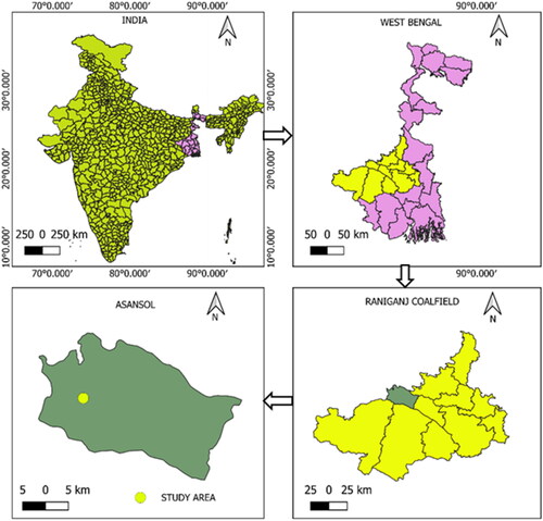
The study area lies in the Raniganj Coalfield, located in eastern India. This coalfield area covers approximately 1130 km2 between 23°25 N and 23°50 N in latitude and 86°38 E and 87°20 E in longitude (Murthy et al. Citation2010), including the districts of Burdwan, Birbhum, Bankura, and Purulia in West Bengal and Dhanbad in Jharkhand. The Raniganj coalfield area is significant for coal production. The Eastern Coalfield Limited (ECL) runs 98 mines in the Raniganj coalfield, 77 underground (UG) mines and 21 opencast mines. Coalfields have proven reserves of 16.9 billion tonnes. An opencast coal mine from the Raniganj Coalfield area was selected for this investigation. The locations of the study area are shown in . The top-to-bottom method was used for dump construction with multiple bench stages in the mine. An internal dumping approach was used for the OB management in the decoaled mine area.
Figure 2. Location of the study area Raniganj Coalfield, West Bengal, India.
Material and methodology
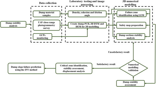
This study is completed in three sections. The dump image data collection and 3D reconstruction using UAV photogrammetry and image processing techniques are described in the first section. The second section discusses the 3D modelling for slope stability analysis and numerical validation of the failure zone. Displacement and slope failure time prediction are presented in the third section. illustrates the scheme used for dump stability analysis.
Figure 3. Scheme for large dump CZI identification and failure prediction.
Geotechnical investigation
Geotechnical parameters play a significant role in numerical simulation. Modelling results depend on the characteristics of the material shear strength. Therefore, the dump material geotechnical investigation mainly focuses on the material shear strength parameters and unit weight. Numerical modelling is becoming a popular and reliable approach for analysing complex structure stress-strain, stability, and displacement. For the dump slope numerical analysis, unit weight (kN/m3), friction angle (°), and cohesion (kPa) are required as input parameters. Hence, these geotechnical parameters are necessary to investigate the slope stability at a preliminary stage. Dump material samples were collected from the active dump site for laboratory testing. The collected dump material samples were loose soil, broken stone, clay, and silt. The dump material shear strength parameters are determined by soil triaxial test (undrained and unconsolidated) according to ASTM D2850. Cohesion, density, and frictional angle are necessary for advanced technical assessment (Khanal et al. Citation2012). The results of dump material cohesion and friction angle are shown in .
Figure 4. Laboratory testing (a) dump material soil triaxial test results graph and (b) compaction curves for the dump material.
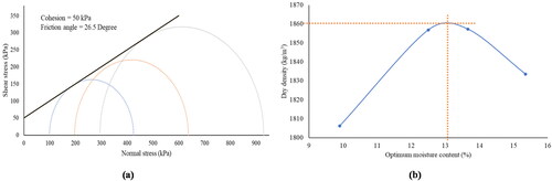
Compaction tests were performed according to the Indian Standard (IS 2720) Part 6 (1965). The dry and bulk density of the OB material were determined using a compaction test. This test achieved a material density by repeatedly hammering and removing the void space. The compaction test results indicated that the optimal moisture levels varied between 10.50% and 16.24%, whereas the maximum dry unit weight varied from 15.05 to 18.8 kN/m3. shows the compaction curve for the dump material.
UAV close-range photogrammetry survey and dump 3D reconstruction
Dump image data were collected using a UAV photogrammetry survey platform. A DJI Air 2S drone was employed for the dump images collection. A vertical intersection route design was used for flight paths (Ma et al. Citation2023). Dump images were collected using a grid flying path (S-path), as shown in . Image overlap is significant in terms of the accuracy of 3D reconstruction. The image collection employed an 85% end gap along the flight path and an 80% side gap along the path (Xue et al. Citation2023). In principle, the front image overlap should be 75% or greater, and the side image overlap should be 65% or greater. UAV flying height will be fixed at the dump images collection time because irregular flying height creates an error in 3D model reconstruction. Therefore, 50 m flying height from the dump top surface was used for the UAV photogrammetry survey. Six hundred digital images were collected from the UAV photogrammetry survey, which takes more than one hour.
Figure 5. Approaches used for the dump data collection are (a) UAV flying path, (b) field survey and ground control points (GCPs) measurement, and (c) workflow of dump 3D reconstruction.
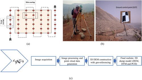
Dump surface realistic 3D surface reconstruction is vital for actual ground conditions with dump stability analysis. The dump’s 3D reconstruction and digital elevation model are created using image processing tools like Pix-4D Mapper and CloudCompare software. The SfM computing algorithm was used for the dump surface PCD generation. The Poisson Surface Reconstruction computing algorithm constructed a smooth surface for mine dump surface using dump surface PCD. It aims to create a 3D mesh surface of the dump.
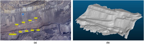
On the other hand, a UAV photogrammetry survey with ground control points (GCPs) measurement survey was conducted using Total Station (Sokkia 330 R), as shown in . illustrates the dump 3D reconstruction workflow used in this investigation. shows the active dump site’s reference point and GCPs distribution. GCPS is required for actual shape and elevation with dump digital elevation model creation. These GCPs are imported into the Pix-4D Mapper with a unique ID number. After model processing, the actual shape and size dump DEM was generated in different file formats. DEM is created in the CAD file (.stl) format ().
Figure 6. Mine dump (a) a picture showing the full GCP distribution spread at the dump site, with orange colour triangles and (b) a digital elevation model after GCP processing.
Limit equilibrium analysis
LEM was used to assess the stability of the rock slope (Sarat et al. Citation2020; Congress and Puppala Citation2021; Anton et al. Citation2022). Recently, several studies have been conducted to predict slope stability (Kumar Behera et al. Citation2016). 3D modelling was used for hill slope stability analysis (Congress et al. Citation2021). Bishop method considers the force and moment equilibrium, which makes it suitable for analysing potential failure surfaces on both circular and non-circular surfaces. The dump susceptible zone stability is analysed in this study using 3D LEM. The Mohr-Coulomb failure criteria was used for the slope stability analysis. The input parameters of the dump material are listed in .
Table 1. Dump material properties investigated by laboratory testing.
A safety map has been prepared for the rock slope stability analysis (Kumar and Ismail Citation2020). The safety map preparation procedure is as follows: Initially, a dump 3D reconstruction was created using the UAV image data. Finally, the 3D model was imported into the Slide-3D software, and the slope stability was analysed. This study applied the grid search method to set the slip surface entrance and exit ranges for potential slip surface searching. Entrance and exit ranges were applied to the entire dump. The auto-grid search technique was used for the FOS. The entire dump slope stability analysis used the FOS contour map legend.
Numerical modelling
The numerical modelling performed in this study utilised the Itasca software (Flac3D) to simulate dump stability and creep behaviour. The mathematical model, derived from continuum mechanics principles, was solved using the finite-difference approach. This research incorporates two constitutive models in its numerical modelling framework: the Mohr-Coulomb and creep models. The creep model can simulate the behaviour of the slope with time. The Mohr-Coulomb model is used for the dump slope failure and FOS calculation.
The dump model length, width, and height were 900, 450, and 104 m, respectively. The dump slope angle is 38°. Dump soil and broken materials were simulated using solid elements. Homogeneous material was used to simulate the dump slope stability. Simultaneously, it mimicked the actual ground condition of the dump, applied the gravity force and calculated the slope FOS and displacement.
For the dump stability analysis (2D and 3D modelling), material parameters are used in the numerical model. The Mohr-Coulomb model was used to determine the constitutive relationship of the dump material. The shear strength reduction (SSR) approach was implemented for dump slope stability analysis and critical zone identification. These equations were used for the dump slope FOS calculation.
(1)
(1)
(2)
(2)
Inverse velocity method
The inverse velocity approach was introduced by Fukuzono in 1985, and subsequent studies further explored its use in the context of open-pit slope instability. The inverse velocity technique was used to determine the displacement rate of the critical slope. Graph the inverse of the displacement rate as a function of time (inverse velocity as a function of time). As the velocity or rate of displacement increased, the inverse velocity approached zero. This establishes a definitive objective for anybody seeking to forecast the duration until collapse because a linear regression analysis may be used to determine the projected point of intersection on the horizontal axis. After that, the intercept provides an estimate of the anticipated failure time.
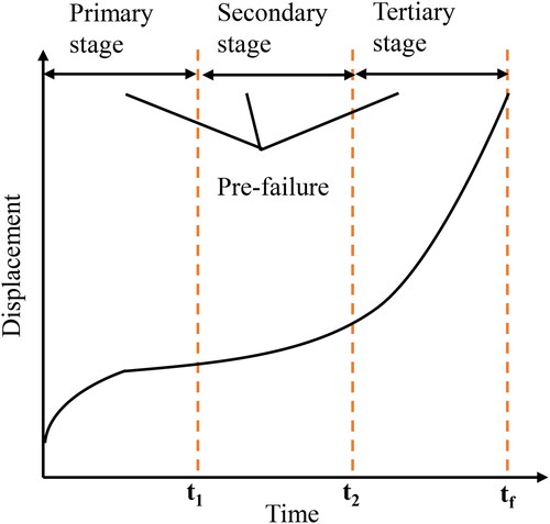
In the failure, displacement plays a vital role, as discovered by Saito. Saito proposed a method to predict the landslide time (tf) based on the creep theory (Saito Citation1965). In this theory, slope failure occurs in three typical failures: primary, secondary and tertiary (). This paper also used the creep theory to predict slope failure time based on the slope creep behaviour analysis.
Figure 7. Three different stages of failure.
Results
Dump stability analysis using 3D LEM
Numerical modelling tools are widely used in geotechnical engineering for rock and slope stability analysis. For large natural and artificial slope structures, mine slope stability analysis is challenging for researchers. This study aims to develop a robust, inexpensive, and simple approach for estimating the stability of large dump slopes using UAV technology and 3D modelling. 3D LEM software rapidly estimated the slope FOS and multiple CZI.
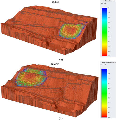
The UAV survey covered a 0.6 km2 area of internal dump for stability analysis. The geometric parameters of the dump are shown in . The 3D global minima method was used for the slope stability analysis. The static condition dump slope FOS is 1.2 (). The study area lies in earthquake zone II with a horizontal seismic coefficient (kh) of 0.16. Seismic loading reduces slope stability and triggers slope failure. Under seismic conditions, the dump slope FOS was 0.9. This study found that seismic loads can cause slope collapses. shows the failure zone for the seismic loading. shows that the dump fails unpredictably if unplanned OB dumping occurs.
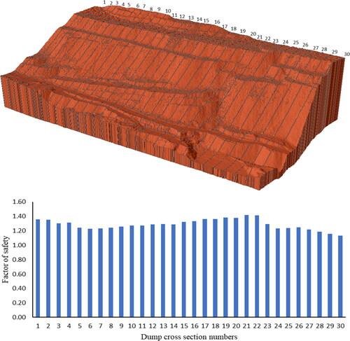
Figure 8. Illustration of the dump geometry parameters in a realistic 3D model of mine dump.
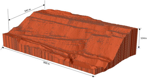
Figure 9. Dump slope stability results under (a) gravity force and (b) seismic loading.
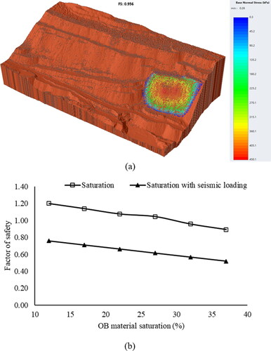
The dump material saturation will increase due to the rainfall events. The rainfall water infiltrates the dump mass and generates the pore water pressure in the dump slope. The pore water pressure may be a reason for dump slope failure. Slope failure is triggered by high-intensity rainfall, infiltrating rainfall water, and increasing material saturation (Mori et al. Citation2017; Lazzari and Piccarreta Citation2018; Zhu et al. Citation2019; Nguyen et al. Citation2022). Therefore, the stability analysis of a large internal dump in a saturated condition is essential for the mining administration. Because of the rainfall conditions, the dump may be failing. However, the static condition in the dump is stable. The dump material’s optimum moisture content was used in the static condition in dump slope stability analysis, and stability results are seen in . Increasing the saturation of dump material decreases the stability of the dump slope. Therefore, the dump slope stability analysis is essential with the saturation conditions. Different saturation conditions were used for the dump slope stability analysis, such as 12%, 17%, 22%, 27%, 32%, and 37%. In this investigation, we observed that the stability of the dump slope decreased with the increasing saturation of dump material, as seen in . shows the dump slope stability under saturation conditions when the dump material is 32% saturated. The study area lies in earthquake zone II with a horizontal seismic coefficient (kh) of 0.16, and different saturation conditions were used for slope stability analysis, such as 12%, 17%, 22%, 27%, 32%, and 37% (). This investigation results will be helpful for understanding the role of seismic load in saturation conditions. This study’s results indicate that the increasing saturation affects dump slope stability under gravity force. When dump material is saturated (12% to 37%), at this condition, seismic loading will fail the dump slope, creating havoc in the mine area. As seen in , OB material saturation and seismic loading have drastically reduced the slope factor of safety. Hence, dump critical zone stability is essential, so a proper drainage system and multiple benches will be constructed on the dump slope face so that dump critical zone stability can improve and avoid a slope collapse in the rainy season.
Figure 10. Dump slope stability with saturation (a) dump stability when OB material is 32% saturated, and (b) saturation effect on the dump slope stability.
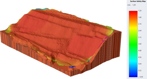
In this study, a safety map has been created to assess an entire dump stability. shows the surface safety map obtained using the simplified bishop method and superimposed on the dump model. Some critical zones were observed in the safety map profile, as shown in , and the map contour profile was prepared based on the FOS results. A safety map helps to assess the stability of the entire dump slope in a single dump model. The coloured legend describes the safety of the entire dump.
Figure 11. Safety map of the entire dump based on 3D LEM.
Critical zone of Interest identification
A multimodel optimization function was added to address some of the actual complexities of the slope stability analysis. Typically, slope stability analyses concentrate on locating a single slip surface. However, in actual field conditions, a slope frequently contains multiple critical regions that may fail instead of a single critical region. With the multimodel optimization option, the user can now instruct the algorithm to seek multiple local minima rather than a single critical minimum, referred to as multimodal particle swarm optimisation (PSO). PSO is a swarm intelligence approach used to determine the best solution in a given search area. The most significant parameter was the radius of the search space. The number of local minima found equals the number of particles in the search (50 particles by default). The radius option eliminates comparable surfaces and considers only the most significant local minima in each region. In this investigation, 3D LEM was used for the CZI identification.
Multiple options consider both the global minima computed from the single option and the local minima computed from multiple options and return the three most critical minima. A spline failure surface was selected, and a particle swarm grid search was used to identify multiple CZI. This implies that the global minima of multiple options are always at least as important as the minimum of a single option. It is a helpful method and a step towards contemplating critical regions throughout the dump instead of focusing on the most critical region alone.
The internal dump geometry is not uniform. Therefore, multiple CZI will be helpful for stable dump construction. The identification of multiple critical zones is essential for large dump stability analysis. The investigation results show the critical zones in . This investigation indicated that failure zone I had a lower safety factor than zones (II and III). Zone I was susceptible to static conditions. Zones II and III were susceptible to seismic loading. lists the failure zone areas and FOS. Under dynamic loading, 54,000 m2 of a critical zone may fail.
Figure 12. Multiple critical zone identification using 3D LEM.
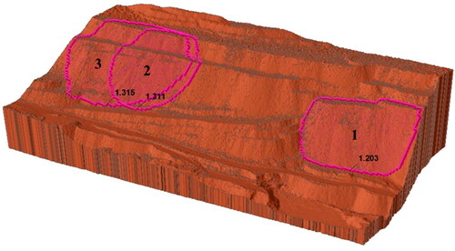
Table 2. Dump failure zone area and factor of safety.
The dump geometry was cut into 30 cross-sections for detailed stability analysis, as shown in . The geometry of the dump section changes with the horizontal distance, and the spacing between each section is 23 m. The minimum FOS was obtained in dump critical zone I. shows the slope stability results for the 30 cross-sections. This investigation found that the 3D modelling slope FOS results were lower than that of 2D modelling. The higher FOS is because the plan-strain condition was used for the slope stability analysis for the 30 cross-sections. Applying self-weight loading conditions has a significant role play in the numerical simulation. Therefore, 3D modelling is helpful for actual field conditions with structure stability analysis.
Figure 13. Dump detailed slope stability analysis with multiple cross-sections.
Numerical validation
Numerical modelling is a reliable approach for estimating slope stability. This study used a 3D finite difference solver to validate critical zone stability. The dump critical zone FOS is 1.2, as seen in . The displacement of dump critical was 0.43 m for static conditions (). The dump slope stability analysis used the shear strength reduction (SSR) technique. LEM and FDM are working on different stability analysis principles. Still, the same critical zone was found in the entire dump.
Figure 14. Dump critical zone identification (a) using 3D-LEM and (b) using 3D-FDM.
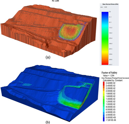
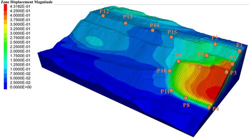
Figure 15. A numerical model shows the locations of points with their corresponding ID numbers.
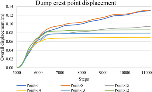
P-1, P-5, P-12, P-13, P-14, and P-15 show the dump slope crest displacements, as shown in . This investigation found that P-1 and P-5 had a maximum displacement of 0.13 m. 0.07 to 0.09 m displacements were observed for P-12, 13, 14, and 15.
Figure 16. Dump crest point displacement found by numerical modelling.
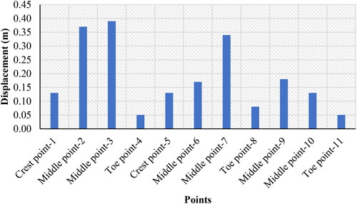
Eleven points were selected for the critical zone displacement measurements, as shown in . The maximum displacement was found in the middle bench, and the minimum displacement was measured for the toe and crest points. The results show that the maximum displacement is 0.39 m, and the minimum displacement is 0.05 m ().
Figure 17. Displacement measurements of dump slope crest, Middle, and toe points.
Dump critical zone stability monitoring
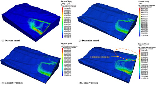
Mine dump slope failure is not a sudden failure. It warns before the slope failure. Opencast mine internal dump stability plays a significant role in smooth mining operations. OB material was continuously deposited on the internal dump by the dumpers. The top-down dumping method was used for internal dumping. The dump geometry parameters are changing with dumping. Therefore, routine dump stability monitoring is essential for avoiding failure accidents in mines. This investigation used four months of UAV photogrammetry survey data for dump geometry 3D reconstruction. After the one-month interval, dump slope stability was analysed using 3D numerical modelling. Dump critical zone stability was analysed from October 2022 to January 2023 (four months). UAV technology and 3D modelling were successfully used for active internal dump stability monitoring. The investigation results indicate that the dump slope stability decreased with the OB dumping, as shown in . The dump slope stability decreased during the unplanned material dumping, as shown in .
Figure 18. Dump critical zone stability with different months.
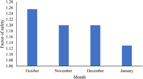
Figure 19. Dump critical zone stability monitoring using a combination of UAV technology and 3D numerical modelling.
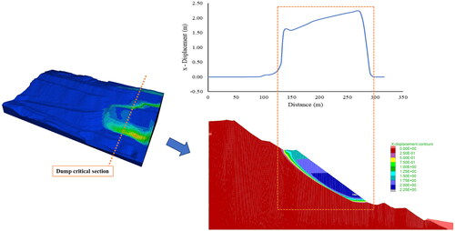
Decreasing dump slope stability may be a reason for the havoc inside the mine. Therefore, this investigation is focused on the dump slope displacement analysis. A critical zone cross-section was selected for this study. This information will help dump slope mitigation mining engineers make decisions. Dump critical zone displacement is also increased, as seen in . 2.2 m horizontal displacement was found in the dump slope toe.
Figure 20. Dump critical slope cross section illustrates the slope horizontal displacement.
Dump slope creep behaviour analysis
Mine dump slopes undergoing long-term effects of gravitational load may gradually displace, leading to slope structures exhibiting settlement displacement and progressive failure. This geotechnical investigation uses numerical modelling to assess the slope creep behaviour. The loose material dump slope’s slow displacement is a long-term effect of gravity. A mine dump is a mixture of fragmented rock and soil materials. The dump materials are discrete. Therefore, the dump slope mass in continuous displacement was observed by mining engineers when the material did not completely consolidate. In this study, settlement and displacement of the dump were investigated using numerical modelling. Mohr-Coulomb model material properties were used for the creep modelling, and Flac2D software was used to simulate the dump slope creep behaviour. The investigation results show that the displacement of the dump slope increased with time and tended to be the dump slope stabilised after 500 days.
For the dump creep behaviour analysis, seven history points (2, 3, 4, 5, 6, 7, and 8) were selected along the dump slope (). shows the dump slope displacement with time. The settlement time of the dump slope is 500 days, as seen in .
Figure 21. Dump slope settlement (a) numerical model with history points and (b) dump surface displacement history with monitoring points.
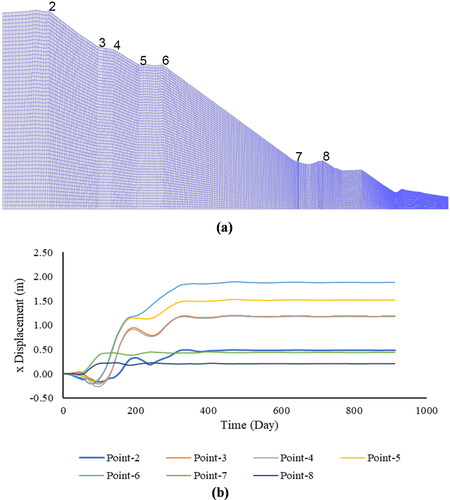
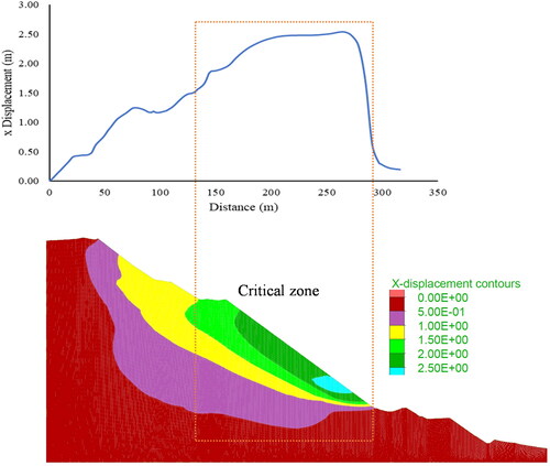
This study will help calculate the displacement time of the dump settlement. The working area was at the greatest distance from the dump slope in the field. Hence, the settlement displacement had a negligible influence on the working area. The horizontal displacement was analysed along the dump slope, as shown in . Maximum displacement was found in the dump slope middle bench from 1.50 − 2.50 m. Maximum displacement was measured at the dump slope toe part.
Figure 22. Along the dump slope displacement analysis using numerical modelling.
Dump critical zone slope failure prediction using inverse velocity method
Mine slope failure prediction is vital for slope failure mitigation and miner safety. Progress slope deformation is generally monitored using slope stability radar (SSR), GPS, laser scanner and real-time sensors. However, this study uses a numerical modelling technique for dump slope failure prediction. For slopes, geotechnical parameters play an essential role in stability. Therefore, this study uses numerical modelling for the dump slope behaviour analysis. Forecasting slope failure events is essential for the industry. Several techniques have been suggested to address this problem in recent years, drawing on the analysis of displacement monitoring data. Among of the many methods considered, the Inverse Velocity (INV) method has proven to be highly successful in predicting the exact moment. The progressive displacement of the dump slope was analysed ().
Figure 23. Dump slope displacement measured with time.
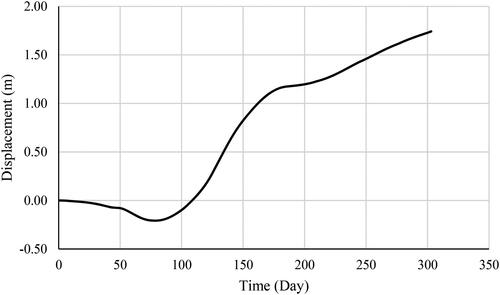
The linear INV method was used for the dump slope failure prediction. Point-6 displacement history was used for failure prediction because the maximum displacement was found. shows the dump slope displacement for Point 6. In this investigation, the self-weight of the dump was considered for the slope failure prediction. The long-term effect of gravity on the dump slope can be observed as the slope slows down over the years. Dump creep behaviour analysis data was used in this INV method for the slope failure prediction. The INV chart can be generated with velocity (d/m) as the Y-axis and time (day) as the X-axis. The linear equation and R2 value were derived from the provided graph. The time required to predict failure was derived from the equation provided in the INV chart, as shown in .
Figure 24. Slope failure prediction (a) linear inverse velocity (INV) graph, and (b) forecasting the dump slope failure time using the linear INV method.
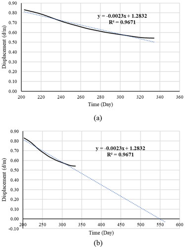
This study used 303 days of displacement data for the progressive displacement analysis (). For the INV method, the maximum displacement rate data was used between 203 and 333 days. A slope failure prediction chart was prepared, as shown in . The R2 value for the INV method was 0.96. According to the investigation results, the dump slope failed after 550 days. This study provides a scientific approach for dump slope failure prediction.
Discussion
Dump image data collection and 3D reconstruction
For dump 3D reconstruction, dump image data collection techniques play an important role. Different flying paths are used for data collection, such as O-path, rectangular path, zigzag path, and S-path flying path (Christy et al. Citation2017). shows the S-path for dump image data collection. This enhancement is intended to increase the UAV coverage area by decreasing the gap between the tracks. The S-flying path is suitable for high-density dump image data collection. Some studies have suggested that increasing the overlap or inserting cross-strips in aerial picture blocks may aid in reducing systematic mistakes caused by increased redundancy (Gerke et al. Citation2016; M. Gerke et al. Citation2016). The increasing UAV attitude also affects UAV flight time and energy consumption. Wind speed also affects the image data collection process.
Precise and evenly dispersed GCPs are required for dump 3D reconstruction (Nesbit and Hugenholtz Citation2019). The GCPs describe the exact direction and size within an external coordinate system and set limits on bundle movement (James and Robson Citation2014; Rupnik et al. Citation2015; Eltner et al. Citation2016; James et al. Citation2017). Results show that GCPs are essential for dump 3D reconstruction with the actual size and shape. The application of real-time kinematic global navigation satellite systems (RTK-GNSS) to UAV orientation sensors has emerged as a potential strategy for direct georeferencing, obviating the need for ground control points.
An image processing tool is required for 3D reconstruction of the dump surface. Although software packages may only provide users with a few processing choices, choosing the right way to match images is vital so that the processing can succeed. A matching technique that does not work with a picture set can result in poor processing. One of the disadvantages of this study is that it considers only the performance of a particular software package, the Pix-4D mapper. Although the Pix-4D mapper is a well-known and extensively used commercial solution for SfM, notably in the processing of oblique pictures, its dependability has been regularly established in prior research (Moe et al. Citation2016; Ostrowski and Bakuła Citation2016; Vacca et al. Citation2017).
Slope stability analysis
Assessing the stability of the entire dump in an opencast mine is tedious. Many approaches have been developed for slope stability analysis. The dump stability assessments were based on remote sensing and 3D modelling. This study focuses on the combination approach of image processing and 3D modelling. Remote sensing data only provides the dump surface DEM, change detection and volume; however, dump mass internal behaviour analysis is also significant for the stability investigation. Therefore, this study uses a combination of remote sensing techniques for the dump realistic 3D model creation and numerical modelling for the dump failure zone identification.
Creating an actual field condition in a virtual digital 3D model is important for understanding the actual field condition and relating it to the field. Therefore, many researchers have used spaceborne and airborne remote sensing techniques for 3D model construction. This study introduces a sustainable, low-cost dump slope stability analysis approach with actual field conditions. In this study, different types of analysis results are included for the stability analysis. The safety map was constructed using a 3D limit equilibrium analysis for stability assessment (Kumar and Ismail Citation2020; Congress et al. Citation2021). This approach is reliable for large dump stability assessment.
This study used the particle swarm optimisation (PSO) intelligence method to identify multiple failure zones in the entire dump. PSO approach can be helpful for stability analysis of the entire dump. Dump slope stability has been analysed using the PSO approach (Syahputra et al. Citation2021).
Real-time mine slope monitoring techniques measure slope displacement with respect to time; however, this study analysed the stability of the dump after a one-month interval. This study used a numerical modelling tool and considered realistic dump 3D geometry with geotechnical parameters for stability assessment and failure zone identification. This approach is cheaper and more effective for slope failure mitigation. Hill, road-cut, and mine large slope susceptible zones can be identified using this approach.
Limitations
Although the combination of UAV technology and a 3D modelling approach is more effective than the traditional methods, this approach has some limitations. In a dump picture, the shadows and background can be affected by changes in the amount and state of light caused by weather. For example, natural illumination can significantly affect the quality of digital aerial photographs. Using data from four or more flights conducted at various hours under varied light conditions is possible, but it requires additional time in both the collection and elaboration stages (Khanal et al. Citation2012). Even if attention is paid to the optimal time of day for flying, depending on the light and cliff exposure circumstances, there may be spots constantly in the shadow (Ma et al. Citation2023). Therefore, a laser scanner UAV platform was used to avoid this problem. UAVs cannot be used in no-fly zones, which include heavily populated areas, landing strips near airports, or military areas. Post-processing is time-consuming and requires a powerful computation facility (the latest generation of i7 processors, 64 GB RAM, and a 6 GB dedicated video card).
The dump slope stability was analysed with static and seismic conditions. The dump material is discrete. This study assumes a homogenous material property for stability analysis. The discrete element method (DEM) will be more helpful for the dump slope failure analysis. The aim was to identify the failure zone and prepare a safety map of the internal dump. The proposed approach is not suitable for real-time monitoring; it takes time to examine the results of slope stability and determine the CZI. Slope stability radar (SSR) is more expensive for slope stability monitoring and failure-zone identification. This approach is cheap and accurate for realistic large dump stability analysis. This study ensures the existence of a failure zone. Other factors will be considered in the future, such as the effect of nearby blasting activity, rainfall intensity and material spatial variation.
Conclusions
This paper describes a sustainable scheme for the large dump critical zone of interest identification and critical zone stability monitoring. The entire internal dump stability analysis used UAV close-range photogrammetry, image processing, and realistic 3D modelling. When this method was applied to evaluate the stability of a dump slope, the following findings were obtained:
The dump critical zone was stable under the gravity force. However, the results of dump stability under seismic and rainfall conditions are not favorable.
Through this investigation, dump slope critical zone stability decreasing reason was identified. A different month’s 3D model was used for the numerical modelling. Unplanned overburden material deposition is the reason for dump slope stability decreasing.
The UAV close-range photogrammetry technique is reliable for collecting large dump image data. A combination of UAV photogrammetry and 3D modelling can be used for the dump slope stability monitoring. This study successfully implements this approach.
The multiple critical zone identification results indicate that complex geometry dump slopes have the possibility of various failures. It is a reason for the dump’s unplanned dumping and poor management. The multiple critical zone identification results show that failure zone I was more susceptible to the other two zones.
Geotechnical and geometric data are used for safety map generation of realistic 3D dumps. This type of map will be helpful for complete dump stability assessment based on the safety map contour.
A critical zone is generated owing to unplanned dumping, and the loose soil rock mass is prone to failure. A multiple-stepping dump is an alternative to a stable dump construction.
The numerical modelling results of the dump section show that the complete settlement of the dump takes time in the year. Based on this investigation, the complete dump displacement was analysed. This will help in making decisions regarding the stable dump and failure mitigation.
The creep modelling results indicate that the displacement is from 0 to 2.5 m along the dump slope surface. When the dump time is above 400 days, the numerical simulation results show that the settlement displacement of the history point is a maximum of 2.5 m, respectively.
The use of the inverse velocity approach may be advantageous in cases where there is an absence of corroborating evidence from previous studies. Nevertheless, the inverse velocity is susceptible to several factors, such as rainfall, seismic conditions, and the disturbance of loose materials. These factors can lead to misleading slope failure predictions.
As part of the present study, a stable dump requires optimum geometry parameters. Further investigation will be required to identify the optimum geometry parameters. Future research will focus on dump slope stability. This study will aid in planning dump construction operations, including the selection of appropriate equipment and the number of team members required for dumper loads. This approach is helpful for geotechnical instability-related hazard-time predictions.
Disclosure statement
The author declares that there is no conflict of interest regarding the publication of this paper.
Data availability statement
The data that support the findings of this study are available on request from the corresponding author. The data are not publicly available due to privacy or ethical restrictions.
Additional information
Funding
References
- Anton HM*, Sendrós A, Ercoli L, Deidda U, Rivero C. 2022. The use of geophysical data in the evaluation of landslide stability. SSRN [Internet]. [accessed 2023 Nov 6]:1–30. https://ssrn.com/abstract=4073276.
- Bar N, Kostadinovski M, Tucker M, Byng G, Rachmatullah R, Maldonado A, Pötsch M, Gaich A, McQuillan A, Yacoub T. 2020. Rapid and robust slope failure appraisal using aerial photogrammetry and 3D slope stability models. Int J Min Sci Technol. 30(5):651–658. doi: 10.1016/j.ijmst.2020.05.013.
- Chand K, Koner R. 2023a. Journal of mining and environment (JME) internal mine dump slope stability and failure zone identification using 3D modelling. Journal of Mining and Environment (JME) [Internet]. 14(4):1105–1119. doi: 10.22044/jme.2023.13013.2360.
- Chand K, Koner R. 2023b. Failure zone identification and slope stability analysis of mine dump based on realistic 3D numerical modeling. Geotech Geol Eng. 42(1):543–560. doi: 10.1007/s10706-023-02588-1.
- Chen Y, Tong Y, Tan K. 2020. Coal mining deformation monitoring using SBAS-InSAR and offset tracking: a case study of Yu County, China. IEEE J Sel Top Appl Earth Observations Remote Sensing. 13:6077–6087. doi: 10.1109/JSTARS.2020.3028083.
- Christy E, Astuti RP, Syihabuddin B, Narottama B, Rhesa O, Rachmawati F. 2017. Optimum UAV Flying Path for Device-to-Device Communications in Disaster Area. In: 2017 International Conference on Signals and Systems. [place unknown]; p. 318–322.
- Congress SSC, Puppala AJ. 2021. Geotechnical slope stability and rockfall debris related safety assessments of rock cuts adjacent to a rail track using aerial photogrammetry data analysis. Transp Geotech. 30:100595. doi: 10.1016/j.trgeo.2021.100595.
- Congress SSC, Puppala AJ, Kumar P, Banerjee A, Patil U. 2021. Methodology for resloping of rock slope using 3D models from UAV-CRP technology. J Geotech Geoenviron Eng. 147(9) doi: 10.1061/(asce)gt.1943-5606.0002591.
- Czikhardt R, Papco J, Bakon M, Liscak P, Ondrejka P, Zlocha M. 2017. Ground stability monitoring of undermined and landslide prone areas by means of sentinel-1 multi-temporal InSAR, case study from Slovakia. Geosciences (Switzerland). 7(3):87. doi: 10.3390/geosciences7030087.
- Dash AK. 2019. Current science association analysis of accidents due to slope failure in Indian opencast coal mines. 117(2):304–308. doi: 10.2307/27138249.
- Eltner A, Kaiser A, Castillo C, Rock G, Neugirg F, Abellán A. 2016. Image-based surface reconstruction in geomorphometry-merits, limits and developments. Earth Surf Dynam. 4(2):359–389. doi: 10.5194/esurf-4-359-2016.
- Gerke M, Nex F, Remondino F, Jacobsen K, Kremer J, Karel W, Huf H, Ostrowski W. 2016. Orientation of oblique airborne image sets: experiences from the ISPRS/Eurosdr benchmark on multi-platform photogrammetry. In: International Archives of the Photogrammetry, Remote Sensing and Spatial Information Sciences - ISPRS Archives. International Society for Photogrammetry and Remote Sensing; Vol. 2016-January, p. 185–191. doi: 10.5194/isprsarchives-XLI-B1-185-2016.
- Gu T, Wang J, Fu X, Liu Y. 2015. GIS and limit equilibrium in the assessment of regional slope stability and mapping of landslide susceptibility. Bull Eng Geol Environ. 74(4):1105–1115. doi: 10.1007/s10064-014-0689-2.
- Hao J, Zhang X, Wang C, Wang H, Wang H. 2023. Application of UAV digital photogrammetry in geological investigation and stability evaluation of high-steep mine rock slope. Drones. 7(3):198. doi: 10.3390/drones7030198.
- Igwe O, Ayogu CN, Maduka RI, Ayogu NO, Ugwoke TAS. 2023. Slope failures and safety index assessment of waste rock dumps in Nigeria’s major mines. Nat Hazards. 115(2):1331–1370. doi: 10.1007/s11069-022-05597-0.
- Iqbal U, Riaz MZB, Zhao J, Barthelemy J, Perez P. 2023. Drones for flood monitoring, mapping and detection: a bibliometric review. Drones. 7(1):32. doi: 10.3390/drones7010032.
- James MR, Robson S. 2014. Mitigating systematic error in topographic models derived from UAV and ground-based image networks. Earth Surf Processes Landf. 39(10):1413–1420. doi: 10.1002/esp.3609.
- James MR, Robson S, d‘Oleire-Oltmanns S, Niethammer U. 2017. Optimising UAV topographic surveys processed with structure-from-motion: ground control quality, quantity and bundle adjustment. Geomorphology. 280:51–66. doi: 10.1016/j.geomorph.2016.11.021.
- Jensen JLR, Mathews AJ. 2016. Assessment of image-based point cloud products to generate a bare earth surface and estimate canopy heights in a woodland ecosystem. Remote Sens (Basel). 8(1):50. doi: 10.3390/rs8010050.
- Junaid, Muhammad, Abdullah, Rini Asnida, Sa’ari, Radzuan, Rehman, Hafeezur, Shah, Kausar Sultan, Alel, Mohd Nur Asmawisham, Zainal, Ir. Zuraini, Zainuddin, Nurul Eilmy, Rafi Ullah,. 2022. Quantification of rock mass condition based on fracture frequency using unmanned aerial vehicle survey for slope stability assessment. J Indian Soc Remote Sens. 50(11):2041–2054. doi: 10.1007/s12524-022-01578-9.
- Kainthola A, Verma D, Gupte SS, Singh TN. 2011. A coal mine dump stability analysis—a case study. GM. 01(01):1–13. doi: 10.4236/gm.2011.11001.
- Karam S, Nex F, Chidura BT, Kerle N. 2022. Microdrone-Based Indoor Mapping with Graph SLAM. Drones. 6(11):352. doi: 10.3390/drones6110352.
- Khanal M, Adhikary D, Balusu R. 2012. Numerical analysis and geotechnical assessment of mine scale model. Int J Min Sci Technol. 22(5):693–698. doi: 10.1016/j.ijmst.2012.08.017.
- Koner R. 2021. Estimation of optimum geometric configuration of mine dumps in Wardha valley coalfields in India: a case study. J Mining Environ. 12(4):907–927. doi: 10.22044/jme.2021.10979.2074.
- Koner R, Chakravarty D. 2011. Earthquake response of external mine overburden dumps: a micromechanical approach. Nat Hazards. 56(3):941–959. doi: 10.1007/s11069-010-9602-x.
- Koner R, Chakravarty D. 2016. Numerical analysis of rainfall effects in external overburden dump. Int J Min Sci Technol. 26(5):825–831. doi: 10.1016/j.ijmst.2016.05.048.
- Kumar Behera P, Sarkar K, Kumar Singh A, Verma AK, Singh TN. 2016. Dump slope stability analysis-a case study. Journal Geological Society of India [internet]. 88:725–735. doi: 10.1007/s12594-016-0540-4.
- Kumar A, Das SK, Nainegali L, Raviteja KVNS, Reddy KR. 2023. Probabilistic slope stability analysis of coal mine waste rock dump. Geotech Geol Eng. 41(8):4707–4724. doi: 10.1007/s10706-023-02541-2.
- Kumar N, Ismail MAM. 2020. 3D limit equilibrium method for rock slope stability analysis using generalised anisotropic material model. Australian Centre for Geomechanics; p. 715–730. doi: 10.36487/ACG_repo/2025_46.
- Laurence D. 2006. Optimisation of the mine closure process. J Clean Prod. 14(3-4):285–298. doi: 10.1016/j.jclepro.2004.04.011.
- Layek S, Villuri VGK, Koner R, Chand K. 2022. Rainfall & seismological dump slope stability analysis on active mine waste dump slope with UAV. Adv Civ Eng. 2022:1–15. doi: 10.1155/2022/5858400.
- Lazzari M, Piccarreta M. 2018. Landslide disasters triggered by extreme rainfall events: the case of montescaglioso (Basilicata, Southern Italy). Geosciences (Switzerland). 8(10):377. doi: 10.3390/geosciences8100377.
- Li C, Gu W, Zheng Y, Huang L, Zhang X. 2023. An ETA-based tactical conflict resolution method for air logistics transportation. Drones [Internet]. 7(5):334. doi: 10.3390/drones7050334.
- Ma K, Li C, Jiang F, Xu L, Yi J, Huang H, Sun H. 2023. Improvement of treetop displacement detection by UAV-LiDAR point cloud normalization: a novel method and a case study. Drones [Internet]. 7(4):262. doi: 10.3390/drones7040262.
- Maiti A, Chakravarty D. 2022. Probabilistic assessment of slope stability using photogrammetric 3D reconstruction: a novel approach. Bull Eng Geol Environ. 81(3) doi: 10.1007/s10064-022-02587-1.
- Markus G, Netherlands T, Przybilla H-J. 2016. Accuracy analysis of photogrammetric UAV image blocks: Influence of onboard RTK-GNSS and cross flight patterns. doi: 10.1127/pfg/2016/02841.
- Moe K, Toschi I, Poli D, Lago F, Schreiner C, Legat K, Remondino F. 2016. Changing the production pipeline - Use of oblique aerial cameras for mapping purposes. In: International Archives of the Photogrammetry, Remote Sensing and Spatial Information Sciences - ISPRS Archives. International Society for Photogrammetry and Remote Sensing; Vol. 41, p. 631–637. doi: 10.5194/isprsarchives-XLI-B4-631-2016.
- Mori A, Subramanian SS, Ishikawa T, Komatsu M. 2017. A case study of a cut slope failure influenced by snowmelt and rainfall. Procedia Eng. 189:533–538. doi: 10.1016/j.proeng.2017.05.085.
- Murthy S, Chakraborti B, Roy MD. 2010. Palynodating of subsurface sediments, Raniganj Coalfield, Damodar Basin, West Bengal. J Earth Syst Sci. 119(5):701–710. doi: 10.1007/s12040-010-0049-y.
- Nesbit PR, Hugenholtz CH. 2019. Enhancing UAV-SfM 3D model accuracy in high-relief landscapes by incorporating oblique images. Remote Sens (Basel). 11(3) doi: 10.3390/rs11030239.
- Nguyen PMV, Wrana A, Rajwa S, Różański Z, Frączek R. 2022. Slope stability numerical analysis and landslide prevention of coal mine waste dump under the impact of rainfall—a case study of Janina Mine, Poland. Energies (Basel). 15(21):8311. doi: 10.3390/en15218311.
- Ollervides-Vazquez EJ, Tellez-Belkotosky PA, Santibañez V, Rojo-Rodriguez EG, Reyes-Osorio LA, Garcia-Salazar O. 2023. Modeling and simulation of an octorotor UAV with manipulator arm. Drones. 7(3):168. doi: 10.3390/drones7030168.
- Open-pit coal mine collapse in China. 2023. [accessed 2023 Nov 2]. https://www.geoengineer.org/news/open-pit-coal-mine-collapse-in-china.
- Ostrowski W, Bakuła K. 2016. Towards efficiency of oblique images orientation. In: International Archives of the Photogrammetry, Remote Sensing and Spatial Information Sciences - ISPRS Archives. International Society for Photogrammetry and Remote Sensing; Vol. 40. p. 91–96. doi: 10.5194/isprsarchives-XL-3-W4-91-2016.
- Poulsen B, Khanal M, Rao AM, Adhikary D, Balusu R. 2014. Mine overburden dump failure: a case study. Geotech Geol Eng. 32(2):297–309. doi: 10.1007/s10706-013-9714-7.
- Rai R, Khandelwal M, Jaiswal A. 2012. Application of geogrids in waste dump stability: a numerical modeling approach. Environ Earth Sci. 66(5):1459–1465. doi: 10.1007/s12665-011-1385-1.
- Rajak TK, Yadu L, Chouksey SK, Dewangan PK. 2021. Stability analysis of mine overburden dump stabilized with fly ash. Int J Geotech Eng. 15(5):587–597. doi: 10.1080/19386362.2018.1503780.
- Ranjan V, Sen P, Kumar D, Saraswat A. 2017. Enhancement of mechanical stability of waste dump slope through establishing vegetation in a surface iron ore mine. Environ Earth Sci. 76(1) doi: 10.1007/s12665-016-6350-6.
- Rupnik E, Nex F, Toschi I, Remondino F. 2015. Aerial multi-camera systems: accuracy and block triangulation issues. ISPRS J Photogramm Remote Sens. 101:233–246. doi: 10.1016/j.isprsjprs.2014.12.020.
- Saito M. 1965. Forecasting time of occurrence of a slope failure. In: proceedings of the sixth international conference on soil mechanics and foundation engineering oxford. Pergamon; p. 537–541.
- Sarat S, Congress C, Asce SM, Kumar P, Patil UD, Tejo AM, Bheemasetti V, Puppala AJ, Asce F, Chair FW. 2020. Three-dimensional stability analysis of rock slope using aerial photogrammetry data. In: Geo-Congress 2020 GSP 318; p. 388–398.
- Schönberger JL, Michael FJ. 2016. Structure-from-Motion Revisited [Internet]. [accessed 2023 Nov 6]. https://github.com/colmap/colmap.
- Shano L, Raghuvanshi TK, Meten M. 2020. Landslide susceptibility evaluation and hazard zonation techniques: a review. Geoenviron Disasters. 7(1) doi: 10.1186/s40677-020-00152-0.
- Syahputra FM, Azizi MA, Marwanza I. 2021. The effect of maximum iteration using 3 dimensional limit equilibrium method in open pit mine. In: IOP Conf Ser Earth Environ Sci. IOP Publishing Ltd; Vol. 894. doi: 10.1088/1755-1315/894/1/012033.
- Vacca G, Dessì A, Sacco A. 2017. The use of nadir and oblique UAV images for building knowledge. IJGI. 6(12):393. doi: 10.3390/ijgi6120393.
- Vemulapalli SC, Mesapam S. 2021. Slope stability analysis for mine hazard assessment using UAV. J Indian Soc Remote Sens. 49(7):1483–1491. doi: 10.1007/s12524-020-01239-9.
- Vinay LS, Bhattacharjee RM, Ghosh N, Budi G, Kumar JV, Kumar S. 2022. Numerical study of stability of coal pillars under the influence of line of extraction. Geomatics Nat Hazards Risk. 13(1):1556–1570. doi: 10.1080/19475705.2022.2088409.
- Wang J, Chen C. 2017. Stability analysis of slope at a disused waste dump by two-wedge model. Int J Min Reclam Environ. 31(8):575–588. doi: 10.1080/17480930.2016.1270498.
- Westoby MJ, Brasington J, Glasser NF, Hambrey MJ, Reynolds JM. 2012. “Structure-from-Motion” photogrammetry: A low-cost, effective tool for geoscience applications. Geomorphology. 179:300–314. doi: 10.1016/j.geomorph.2012.08.021.
- Xu X, Zhao S, Xu C, Wang Z, Zheng Y, Qian X, Bao H. 2023. Intelligent mining road object detection based on multiscale feature fusion in multi-UAV networks. Drones. 7(4):250. doi: 10.3390/drones7040250.
- Xue B, Ming B, Xin J, Yang H, Gao S, Guo H, Feng D, Nie C, Wang K, Li S. 2023. Radiometric correction of multispectral field images captured under changing ambient light conditions and applications in crop monitoring. Drones. 7(4):223. doi: 10.3390/drones7040223.
- Yadav DK, Jayanthu S, Das SK, Chinara S, Mishra P. 2019. Critical review on slope monitoring systems with a vision of unifying WSN and IoT. IET Wirel Sens Syst. 9(4):167–180. doi: 10.1049/iet-wss.2018.5197.
- Yang Z, Li Z, Zhu J, Yi H, Feng G, Hu J, Wu L, Preusse A, Wang Y, Papst M. 2018. Locating and defining underground goaf caused by coal mining from space-borne SAR interferometry. ISPRS J Photogramm Remote Sens. 135:112–126. doi: 10.1016/j.isprsjprs.2017.11.020.
- Yordanov V, Truong QX, Brovelli MA. 2023. Estimating landslide surface displacement by combining low-cost UAV setup, topographic visualization and computer vision techniques. Drones. 7(2):85. doi: 10.3390/drones7020085.
- Zhan L t, Guo X g, Sun Q q, Chen Y m, Chen Z y 2021. The 2015 Shenzhen catastrophic landslide in a construction waste dump: analyses of undrained strength and slope stability. Acta Geotech. 16(4):1247–1263. doi: 10.1007/s11440-020-01083-8.
- Zhu JF, Chen CF, Zhao HY. 2019. An approach to assess the stability of unsaturated multilayered coastal-embankment slope during rainfall infiltration. JMSE. 7(6):165. doi: 10.3390/jmse7060165.