
 ?Mathematical formulae have been encoded as MathML and are displayed in this HTML version using MathJax in order to improve their display. Uncheck the box to turn MathJax off. This feature requires Javascript. Click on a formula to zoom.
Abstract
Real-time monitoring technologies of surface deformation represented by the global navigation satellite system (GNSS) are essential for landslides early warning. Monitoring methods such as GNSS require on-site manual installation. Therefore, it becomes nearly impossible to deploy surface monitoring equipment when landslides are located in high mountain valleys that are challenging for personnel to access, and/or in hazardous situations. We propose an intelligent real-time monitoring and early-warning technology that employs an unmanned aerial vehicle (UAV) as a carrier to deploy GNSS equipment. A system was initially designed with five components: an adaptive sampling GNSS receiver, an intelligent cooperative network transmission module, UAV-dropped GNSS equipment, special delivery UAV, and an intelligent monitoring and early warning cloud platform. This new technology was applied to a real landslide in Gansu Province, China, in 2020. The mean absolute error of 30 days in the east, north, and upward directions were 1.2, 1.3, and 2.9 mm/d, respectively, comparing the deformation velocity between the traditional monitoring station and the UAV-dropped monitoring station. This observation facilitated the successful prediction of a landslide hazard on 27 January 2021, allowing for a timely alert to be issued. Collectively, the results of this study established that UAV-deployed GNSS technology can accomplish unmanned deployment of GNSS equipment for landslide monitoring to ensure early warning issuance in inaccessible and/or high-risk areas.
1. Introduction
Landslide disasters are widespread and recurring global disasters posing significant obstacles to infrastructure development and operations while also causing substantial casualties and economic losses. In China, approximately two-thirds of the land comprises mountainous areas and plateaus that are highly susceptible to landslides (Xu et al. Citation2023). Consequently, China experiences some of the most severe global landslide disasters. A total of 278,880 landslide destabilization events were recorded between 2004 and 2016 (Zhang and Huang Citation2018). Notable examples include the Jiweishan landslide of 2009, Xiaolincun landslide of 2009, Guanling landslide of 2010, Wulipo landslide of 2013, and Xinmo landslide of 2017, which resulted in 99, 465, 99, 161, and 83 fatalities, respectively (Xu et al. Citation2023). The risk and impact of landslide disasters can be substantially diminished through proactive disaster prevention and mitigation measures, with the crucial aspect being the deployment of efficient landslide monitoring and early warning systems (Zhang et al. Citation2021).
The most direct and observable manifestation during landslide development is surface deformation, which is an essential indicator for assessing landslide stability. Surface deformation monitoring technology is the predominant method employed in landslide monitoring and can be categorized as contact monitoring, involving the deployment of equipment on the sliding body, or non-contact monitoring, which does not require on-site deployment. Non-contact monitoring technologies include space remote sensing, 3D laser scanning, photogrammetry, and ground-based radar, among others (Cenni et al. Citation2021; Shi et al. Citation2019). These technologies provide the benefit of extensive coverage and non-contact monitoring, making them particularly suitable for early identification of landslide hazards and medium to long-term monitoring of slow-moving deformations that do not require real-time monitoring (Casagli et al. Citation2023). Contact monitoring technologies include the global navigation satellite system (GNSS), displacement meter, optical fibers, tiltmeters, and so on (Rodriguez et al. Citation2021). Contact-based monitoring technologies offer the advantages of high precision, real-time, and point monitoring, making them suitable for real-time automated monitoring of landslides with severe deformation (Auflič et al. Citation2023). Among these, GNSS is the most frequently employed, providing direct acquisition of three-dimensional vector deformations (Huang et al. Citation2023; Zhang et al. Citation2022). It was successfully applied for real-time early warnings in landslide disaster monitoring to prevent numerous casualties and considerable property damages (Bai et al. Citation2019).
Deploying monitoring equipment on-site by personnel during an unstable or potentially destabilizing landslide stage faces a serious risk to life safety. Furthermore, deploying surface monitoring equipment becomes exceptionally challenging when landslides occur in remote mountainous valleys with complex topography that is difficult for personnel to access. The landslide that occurred in Chamoli, Indian Himalaya, on 7 February 2021 represents a typical example of these high-risk and/or difficult access (HRDA) landslides (Shugar et al. Citation2021). This landslide resulted from land destabilization approximately 5600 m above sea level, causing damage to two hydropower plants and leading to over 200 people being reported as dead or missing. No contact monitoring equipment was installed for real-time monitoring of the sliding body before failure, owing to several challenges in deploying monitoring equipment in such landslide areas (Cui et al. Citation2022). These HRDA landslides are widely present in China. For instance, numerous similar landslide disasters occurred along the route during the construction of the Sichuan Tibet Railway (Lu and Cai Citation2019). However, conventional surface monitoring techniques are not feasible owing to the high altitude and complex terrain of these landslide areas. There is an urgent demand for innovative monitoring technologies to overcome the shortcomings of traditional methods that rely on manual on-site deployment.
A potential solution could involve the development of surface monitoring technology equipped with unmanned deployment devices. Unmanned aerial vehicle (UAV) technology was recently increasingly used in geological disaster investigation, emergency rescue, and deformation monitoring (Silvagni et al. Citation2017). Moreover, GNSS exhibits considerable potential when combined with UAV technology to realize unmanned deployment among contact monitoring technologies.
This study aimed to develop a landslide monitoring and early warning system that can remotely and accurately deploy equipment through UAVs. We propose a novel GNSS technology for real-time landslide monitoring that uses a UAV to drop the GNSS equipment. Further, we utilized this technology during the Dangchuan landslide in 2020 to test its applicability. This technology can realize unmanned, real-time, and intelligent deployment and monitoring of GNSS equipment, providing invaluable support for landslide disaster prevention and mitigation.
The remainder of this paper is organized as follows. A technical system developed for dropping GNSS equipment is introduced in Section 2. Studies conducted on dropping GNSS equipment with UAVs are also presented. The study area and first application of the UAV-dropped GNSS technology are described in Section 3. The landslide monitoring results are analyzed and discussed in Section 4. Finally, the main contributions of this study are summarized in Section 5.
2. System and equipment
We began conducting unmanned monitoring and early warning research on HRDA landslides in 2019 and soon discovered that the successful development of our technology was restricted by the following factors. First, traditional GNSS receivers are characterized by their bulky size, high power consumption, and limited functionality, primarily providing positional information.
Second, traditional communication methods do not effectively meet the demand for constant real-time data transfer in remote landslide areas. Third, substantial challenges exist in developing a lightweight GNSS device that can be dropped by a UAV and securely installed on an intricate landslide surface. Fourth, existing UAVs cannot provide highly reliable autonomous flight and intelligent accurate dropping of GNSS equipment. Finally, the crucial threshold of landslide instability is difficult to ascertain using conventional GNSS data processing and early warning analysis technology due to low monitoring precision, poor reliability, and challenges with multi-parameter fusion.
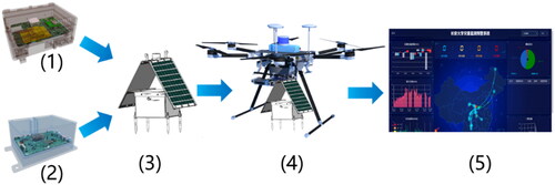
With these limitations in mind, we sought to develop a UAV-dropped GNSS system with five components: adaptive sampling GNSS receiver, intelligent cooperative network transmission module, UAV-dropped GNSS equipment (UDGE), special delivery UAV, and intelligent monitoring and early warning cloud platform. The diagram of the structural relationship between the five parts of the system is show in . This technology is being continuously researched, and the following sections describe some of our research results on equipment development and data-processing technology.
Figure 1. The architecture of the UAV-dropped GNSS system. The adaptive sampling GNSS receiver (1) and the intelligent cooperative network transmission module (2) will be inherited into the UAV-dropped GNSS equipment (3). The UAV-dropped GNSS equipment (3) can be deployed by the special delivery UAV (4). The data processing and early warning analysis work are carried out on the intelligent monitoring and early warning cloud platform (5).
2.1. Adaptive sampling GNSS receiver
A 24-h continuous working mode for GNSS is commonly applied in current landslide monitoring. Consequently, the GNSS receiver requires a large-capacity photovoltaic power generation system (12 V, 55 Ah, 16 kg) to remain functional in the long term (≥7 days) and in the absence of sunlight. However, a power shortage for GNSS receivers may inevitably occur in the following circumstances: (1) The landslide monitoring area faces months of no sunlight due to seasonal weather events, such as snow cover or continuous rainfall; (2) Mountains and vegetation blocks most sunlight from reaching the solar panels of GNSS monitoring equipment, resulting in extremely poor sunlight conditions in some landslide-prone areas. (3) The limited load capacity of the UAV provides a small amount of power to any UDGE. These circumstances hinder the normal functioning of the GNSS receivers (Lee et al. Citation2017).
The evolution of landslides from the initial deformation phase to the unstable failure phase might occur over several days, months, or years (Xu Citation2020). In such cases, a 24-h continuous working mode for GNSS receivers is unnecessary. Further, this method of monitoring has several drawbacks, namely, high electricity consumption, large memory requirement to accommodate the high amounts of data, and rapid deterioration of positioning and communication modules, all of which destabilize the performance of GNSS receivers. Therefore, current GNSS receivers using a 24-h continuous working mode may be unsuitable for landslide environments that lack electricity and have limited sunlight.
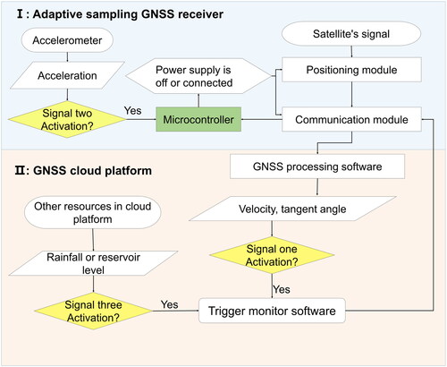
As a response, a GNSS receiver featuring adaptive sampling was developed, wherein the monitoring process can be triggered bilaterally. This activation is prompted by deformation information sourced from the GNSS cloud platform and/or internally acquired acceleration data within the receiver. The detailed design of the receiver is shown in . The upper part of the figure shows some functions of the GNSS receiver, and the lower part presents other functions on the cloud platform. In contrast to a traditional GNSS receiver, the accelerometer and microcontroller are integrated in our new GNSS receiver. The accelerometer in the receiver will operate continuously, while the positioning and communication modules, which are the most power-consuming components within the receiver, will be controlled by the microcontroller, functioning intermittently based on predefined working durations and sampling intervals. The microcontroller controlled the power supply according to three types of trigger signals. Signal one and Signal three are acquired through the cloud platform and transmitted to the receiver via the communication network, whereas Signal two is directly acquired at the receiver terminal. The signal one is the deformation velocity and tangent angle, which are calculated by the GNSS processing software running on the cloud platform. Its primary role is to dynamically adjust monitoring intervals based on varying deformation velocity and tangent angles. This function is contingent upon the proper functioning of the communication module, rendering it non-real-time. Signal two corresponds to the acceleration information of the landslide, as detected by the accelerometer. Its primary role is to initiate the continuous operation of the GNSS receiver upon detecting the sudden acceleration of a landslide. As the accelerometer operates in real-time, this process is executed in real-time. Signal three encompasses additional resources such as rainfall or reservoir level data, which are acquired from the cloud platform. Both the receiver’s sampling intervals and working time are determined by the trigger signals. This design reduces the receiver’s energy consumption while ensuring that the key data on the landslide deformation process are collected. Low-rate observational data are obtained when landslide deformation is slow, for example, no more than 10 min of observation every 2 h. Conversely, if rapid deformation is detected, high-rate observation (e.g. 1 Hz continuous operation) is performed.
Figure 2. Design concept of an adaptive sampling GNSS receiver. (I) GNSS receiver; (II) cloud platform.
The sampling intervals of the GNSS receiver is set by the user. This study adopts an improved tangent angle to adjust the monitoring sampling (Xu et al. Citation2009), which can be expressed by EquationEquations (1)(1)
(1) and Equation(2)
(2)
(2) :
(1)
(1)
(2)
(2)
where
is the transformed dimensionless time function, representing the landslide deformation;
is the cumulative displacement;
is the deformation velocity selected from the time series of the monitoring station at the constant-velocity deformation stage;
represents the tangential angle of
and
and
denote the changes in
and
respectively.
According to the principle that the tangential angle corresponds to the warning level, the sampling intervals of the GNSS receiver should be shorter when the tangential angle is larger (Bai et al. Citation2019). The sampling intervals for the GNSS receiver to switch from a dormant state to active normal monitoring is represented by which is negatively correlated with
The threshold of the trigger signal is expressed by EquationEquation (3)
(3)
(3) :
(3)
(3)
where x is a constant and set to 3600s in this study; users can set it according to their demands. After activating the receiver, the working duration can be set to 5 or 10 min according to the observation environment. After the landslide enters the final unstable failure stage when α exceeds 88°, the data sampling rate is adjusted to 1 Hz continuous real-time observation. The adaptive sampling criteria for the GNSS receiver are listed in .
Table 1. Adaptive sampling criteria of the GNSS receiver.
2.2. UAV-dropped GNSS equipment
The UDGE comprises an adaptive sampling GNSS receiver, a spiral satellite antenna, and a power supply system. Securing a UDGE stably on the landslide surface using a UAV is more complex than the manned installation of traditional GNSS equipment. Thus, two primary issues were considered when designing the UDGE. First, as the payload capacity of a UAV is limited to approximately 6.0 kg, the equipment structure was designed to be as light as possible. Second, stable fixation of the instrument is difficult on complex and often uneven landslide surfaces, such as gravel and vegetation. Moreover, the process is more challenging when an intersection of multiple geological types is present.
We argue that no universally applicable fixed approach can be used in all circumstances. Therefore, to develop the UDGE, we adopted a design principle based on split type and combination according to the application scenarios. depict our first-generation UDGE conceptual design. The equipment comprised the main box in the upper part and foot nails under the lower part. Certain requirements were considered when designing the main box. First, the box must be extremely lightweight, such that it could be carried by a common UAV. Second, the box must accommodate a sufficient power supply. Third, the box must be waterproof and resistant to impact. When designing the lower portion, we incorporated foot nails to ensure traction on the different types of landslide surfaces, which can include dirt, rock, and glaciers. Its design allows for the separation or assembling of the box and foot nails if desired. Moreover, different types of foot nails can be incorporated according to the various landslide types. The UDGE parameters are presented in .
Figure 3. UAV-dropped GNSS equipment (UDGE). (a) structural diagram of UDGE: 1. Hook-hanging mechanism; 2. Device cover; 3. Gain antenna; 4. Power controller; 5. Lithium battery; 6. Device box; 7. Foot nail for attachment to ground surface; 8. Satellite antenna; 9. Flexible solar panel; 10. Solar panel bracket; 11. Adaptive sampling GNSS receiver; 12. Anti-swing. (b) Appearance of UDGE.

Table 2. Parameters of UDGE.
The UDGE introduced in this paper is designed for loess landslides with relatively gentle slopes, and we are continuously researching fixation solutions and UDGE for other scenarios.
2.3. UAV and UDGE deployment scheme
UDGE deployment requires the use of reconnaissance and transportation multirotor UAVs. The initial investigation of the landslide was performed using an off-the-shelf reconnaissance UAV. A transportation UAV was then used to carry the UDGE for deployment. Although many multirotor UAVs are available for commercial and recreational aerial photography, professional UAVs specifically designed for deploying GNSS receivers do not exist. Consequently, after conducting marketing research, we identified the DJI-produced M600 Pro commercial UAV as the most suitable refitting option. This decision was based on various performance parameters, presented in , including payload capacity, endurance time, safety, and obstacle avoidance capability. Following purchase, this UAV was temporarily refitted to better suit our research requirements.
Table 3. Technical parameters of the transportation UAV M600 Pro.
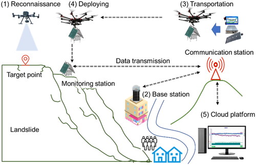
The deployment process of GNSS equipment by UAV can be divided into five steps, as shown in . (1) A reconnaissance UAV is employed to initially investigate the landslide before using the transportation UAV. Detailed information is collected, including the distribution of surface cracks, vegetation coverage, and terrain slope. This information enhances the selection of suitable installation sites that not only facilitates deploy the UDGE but also offers a superior observation environment. (2) The flight routes of the transportation UAV are planned to avoid unnecessary detours, thus improving flight safety and reducing flight time. If public Continuous Operational Reference Systems or previously established stations are available within the area, these may be used for deployment and monitoring. If not, such stations improve UAV navigation accuracy and landslide monitoring precision (using GNSS real-time kinematic technology, RTK), and must therefore be constructed. (3) The transportation UAV carries the UDGE to the target area for deployment. The suitability of the deployment point can be accurately confirmed using images captured from the reconnaissance UAV. (4) High-precision position information of the transportation UAV is obtained using the UAV’s GNSS. Furthermore, the deployment of equipment at a suitable elevation can be autonomously controlled by the control module. (5) GNSS observation data are collected using the GNSS adaptive sampling receiver, and then transmitted to a cloud platform through an intelligent cooperative network transmission module.
Figure 4. Schematic of the UAV-dropped GNSS equipment deployment.
UAV flights are significantly affected by weather conditions, with factors like rain, snowfall, strong winds, extreme heat, and low temperatures being common causes of drone crashes or losses. These meteorological conditions impose certain operational limitations on the UAV deployment technology proposed in this paper. Therefore, the current use of UAV deployment equipment requires favorable weather conditions. The operation of UAVs in the proposed technology is not yet fully automated and requires professional UAV pilots for operation and deployment. For conditions with low visibility, such as nighttime or heavy fog, we are researching intelligent path planning, autonomous navigation, and adaptive control device deployment algorithms. In future research, our research focus will be on exploring the automation of UAV operation and deployment to enhance the on-site applicability of the technology.
Although there are existing limitations in UAV endurance and flight altitude, our requirements for UAV performance are reasonably lenient. As long as UAVs can fulfill the application needs of deploying landslide monitoring equipment over the most challenging distances of a few hundred meters, it can address the practical application requirements for most deployment-difficult scenarios in landslide monitoring. Fortunately, current UAV technology is entirely capable of meeting this level of application demand. Additionally, the use of certain technologies and strategies, such as equipping UAVs with portable charging stations, can significantly augment the effective working duration of UAVs.
With regard to the potential safety impact of GNSS multipath effects in mountainous terrain, on the one hand, the fusion navigation of multiple sensors, including GNSS and inertial navigation, effectively addresses GNSS signal multipath effects in these complex terrains. On the other hand, through careful planning of the drone’s flight path, we consistently ensure minimal multipath effects on the GNSS device carried by the drone during flight through multiple experiments.
2.4. Cloud platform and random function model
After receiving observational data, the GNSS real-time landslide monitoring system, running on the cloud platform, is employed to store, manage, and process the observation data and display the monitoring results (Bai et al. Citation2024; Jing et al. Citation2023; Wang et al. Citation2023). As the satellite antenna of UDGE is closer to the ground, due to its small size, the observation data are highly sensitive to interference caused by mountains or plants, which can cause considerable multipath effect. In addition, the multipath suppression ability for spiral antennas, used by UDGE, is inferior. Collectively, these factors may further lead to poor-quality observation data.
Elevation angle (E) and signal-to-noise ratio (SNR) are important indicators for evaluating the quality of observation data in GNSS positioning. The GNSS observation data quality is positive correlation with E and SNR in a good environment with an open field of vision and no interference. During Real-Time Kinematic (RTK) positioning, the observation conditions of the reference station are typically superior to those of the monitoring station. The SNR information between these two stations (reference station and monitoring staton) is useful for controlling the data quality.
The random function model based on E and SNR is used for data processing, as shown in EquationEquation (4)(4)
(4) :
(4)
(4)
where
is the weight function of
and
and
are the thresholds for excluding satellite observation data;
is the difference between the SNR of base station
and monitoring station
for common-view satellite
at the same epoch time;
and
are the minimum and maximum thresholds of
respectively, which are different values for different stations; and
is the weight reduction coefficient. If
the observation data of the satellite are removed and not used in the construction of the double-difference observation equation. Alternatively, if
≠ 0, EquationEquation (4)
(4)
(4) is used to calculate the weights of the observed values.
2.5. Technical advantages and disadvantages analysis
Compared to existing contact monitoring technologies, the UAV-deployed GNSS equipment technology offers a range of distinct advantages. Firstly, it achieves remote unmanned automatic deployment of equipment, effectively mitigating significant safety risks associated with on-site deployment in hazardous landslide environments. The technology’s autonomous deployment capability, facilitated by drones, eliminates the need for personnel to physically enter landslide sites. This feature proves particularly crucial in complex or hazardous scenarios where the safety of on-site personnel is paramount. Additionally, drones exhibit high mobility and rapid response capabilities, enabling the swift deployment of GNSS equipment. This rapid response is especially advantageous in emergency situations, where quick placement of monitoring devices is essential. For instance, in landslide scenarios characterized by steep slopes that hinder ground equipment transport, this technology significantly reduces the burden of manual deployment, thereby enhancing overall operational efficiency. Furthermore, the technology significantly reduces labor costs compared to traditional manual deployment methods, while maintaining the cost of GNSS equipment at a similar level. Each set of GNSS equipment costs less than 5000 CNY, highlighting the clear cost-effectiveness of this approach.
Despite its notable advantages, the UAV-deployed GNSS equipment technology does face certain challenges. One significant drawback is its dependency on drone and sensor performance. The successful implementation of this technology is directly contingent on the performance of the drone, encompassing factors such as endurance, payload capacity, and stability during flights in adverse conditions like strong winds, low temperatures, and high altitudes. Another limitation lies in the poor adaptability of fixation solutions. Varying terrain types necessitate the adoption of diverse fixation solutions, limiting the overall convenience of the technology. In the face of complex terrain or frequently changing monitoring areas, the need to design suitable deployment plans adds complexity to the technology. Additionally, equipment maintenance poses a challenge as the current deployment equipment lacks recovery functionality, leading to the direct scrapping of faulty equipment. To address this issue, the project team is actively researching equipment recovery technologies to enhance reliability, further reduce GNSS monitoring device costs, and alleviate equipment maintenance difficulties. Lastly, the high cost of drones, including considerations such as drone battery lifespan, maintenance, and the expense of professional drone operators, is a notable disadvantage. However, there is an optimistic outlook, as with an anticipated increase in the frequency of technology application, this cost is expected to decrease significantly through amortization.
3. Experimental overview
3.1. Study area
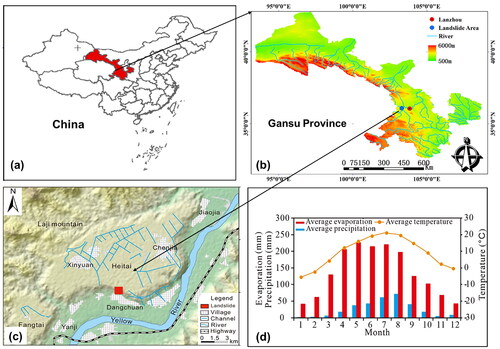
The study area was the Heifangtai tableland which consists of the Heitai loess terrace and the Fangtai loess terrace, and is situated in Gansu Province, China (). Heifangtai is located on the fourth terrace of the Yellow River, with an elevation of 120 m above the river level. It covers an approximate area of 14 km2, is located approximately 60 km from Lanzhou City, and is the capital of Gansu Province. Many people from the reservoir area were relocated to the Heifangtai tableland since the construction of the Liujiaxia and Yanguoxia Reservoirs in 1958. This region is a flat loess tableland formed by the accumulation of Malan loess, which is ideal for farming. Thus, agricultural irrigation activities have been prevalent in this region since 1968 (Kong et al. Citation2021). However, the Heifangtai tableland is located in the arid and semi-arid climate area of the middle temperate zone in Northwest China (Liu et al. Citation2020). The average annual values of evaporation, rainfall, and temperature are approximately 1600 mm, 300 mm, and 8 °C, respectively (Fan et al. Citation2017). In addition, the evaporation is approximately 5 times that of the precipitation in the Heifangtai tableland (). The local government has built 11 irrigation canals that divert water from the Yellow River to help the relocated residents perform agricultural production on the Heifangtai tableland. The combined length of all the irrigation canals is approximately 11.5 km () (Gu et al. Citation2019).
Figure 5. Study area location. (a) The red area is Gansu Province in China. (b) Digital elevation model map (30 m resolution) of Gansu Province. The red dot represents the city of lanzhou, the capital of Gansu Province. Heifangtai is the landslide area, represented by a blue dot. The aquamarine lines represent Rivers. (c) The location of Heitai and Fangtai. The dangchuan landslide is represented by the red-boxed area. (d) Monthly average precipitation, evaporation, and temperature of heifangtai tableland.
Heifangtai tableland exemplifies a typical loess-covered tableland situated within the undulating topography of the Chinese Loess Plateau and is characterized by a predominantly level terrain. This tableland maintains an average elevation of approximately 1710 m, with a gentle slope angle not exceeding 3°. The topography surrounding the Heifangtai tableland is intricately shaped by the courses of rivers and gullies, with the Hulang gully notably eroding and incising the central region shared by Heitai and Fangtai (). Landslides represent the predominant micro-geomorphic feature of Heifangtai.
Figure 6. Geomorphologic features of the heifangtai tableland. (a) Profile location of heifangtai tableland. (b) Profile A-A (35°). (c) profile B-B (254°) (modified from Kong et al. Citation2021).
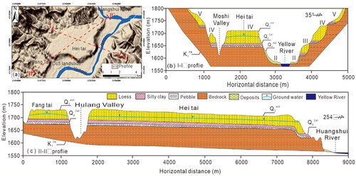
Heifangtai’s stratigraphic composition includes aeolian-loess, silty clay, pebbles, and bedrock (). The upper layer aeolian-loess was deposited in the Late-Pleistocene (Q3) period, with a thickness ranging from 20 to 50 m. This stratum displays water sensitivity, pronounced collapsibility, uniform texture, loose structure, well-developed vertical joints, and moderate mechanical strength. Immediately underlying the aeolian-loess layer is the Upper Pleistocene alluvium. Its upper segment consists of alluvial silty clay that is 4 to 7 m thick, while the lower part comprises a pebble layer, with a thickness ranging from 2 to 5 m (Hou et al. Citation2019). The lowest stratum is the bedrock, which formed during the Tertiary period. The bedrock is predominantly characterized by brown-red and purple-red hues, primarily composed of massive mudstone and sandy mudstone, with minor occurrences of sandstone and conglomerate, and an exposed thickness of approximately 70 m (Zhang and Wang Citation2018).
The silty clay forms an almost impermeable layer owing to its significantly lower permeability coefficient compared to loess, which has a relatively high void ratio. Heifangtai has a long history of heavy water irrigation. Long-term agricultural irrigation on the Heifangtai tableland has led to significant ground subsidence and groundwater rise. The groundwater is infiltrated by agricultural irrigation water and tends to disperse over a long period of time owing to the special geological structure of Heifangtai. The groundwater level has been rising since 1968 (Hou et al. Citation2019). A softening zone was gradually formed under the impact of penetrating water between the lower silty clay and the upper Malan loess, causing the loess to become unstable (Zhang et al. Citation2019). Geological disaster experts refer to this region as the ‘natural laboratory of loess landslides’ since loess landslides frequently reoccur along Heifangtai’s margins () (Bian et al. Citation2022). Field investigation has revealed that the landslide mass has numerous cracks and step-like characteristics between two adjacent cracks (). The cracks are roughly parallel to the edge of Heifangtai. The water seepage is evident at the bottom of Heifangtai, leaving a sizeable salinization area after evaporation ().
Figure 7. Field survey photos of heifangtai. (a) Photograph of dangchuan landslides. (b) The dangchuan landslide and HF09 monitoring station. (c-e) Cracks in the dangchuan landslide. (f) Water seepage at the bottom of heifangtai. (g) a sizeable salinization area remained at the bottom of heifangtai after the evaporation of seepage water.
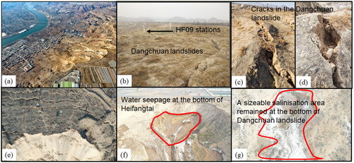
The DC5 landslide presents prominent mudflow characteristics in the slip tongue with the height of the slip cliff of the landslide at 24 m. After the landslide, the cracks in the back edge continued to expand, with the slope still at risk of failure. Meanwhile, the violent movement of the landslide destroyed the on-site deformation monitoring equipment.
3.2. Surface monitoring and landslide details
Our research team installed 13 sets of GNSS monitoring equipment to study the formation mechanism of landslides in Heifangtai on 25 October 2018. These pieces of equipment comprised one base station and 12 monitoring stations, with HF09 serving as an evaluation station. The distribution of each monitoring station and the relative locations of the villages are shown in .
Figure 8. Map of the DC5 landslide that occurred at 2021.01.27. (a) Distribution map of the global navigation satellite system (GNSS) landslide monitoring stations in heifangtai. (b) Photograph of the DC5 landslide. (c) A-A’ geological profile of the DC5 landslide (the location is shown in ).
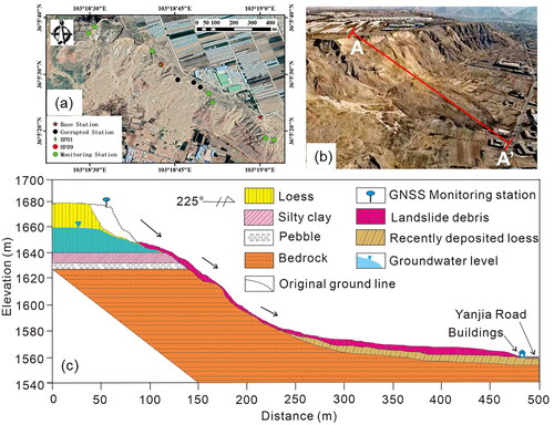
A typical irrigation-induced loess landslide (DC5 landslide) with a volume of approximately 100,000 m3 occurred in the monitoring area at 21:00 (Beijing time, which is equal to GMT + 08:00) on 27 January 2021 (Chang et al. Citation2021). The total landslide area covers 5.39 × 10⁴ m2, encompassing a sliding volume of 4.92 × 10⁴ m3, predominantly sliding along a direction of 225°. The underlying strata within the DC5 landslide zone consist of silty clay, a pebble layer, sandstone, and mudstone (). The elevation of the trailing edge is approximately 1680 m, while the leading edge is about 1550 m (). The sliding is accompanied by abundantly loess debris, which is loosely accumulating in the middle and lower portions of the slope, forming a fan-shaped deposition mass on the front edge (). The sliding distance is 405 m, and the maximum backward distance of the slip cliff retreats by 24 m. The DC5 landslide destroyed farmland and roads on the tableland, and the landslide deposits damaged numerous irrigation channels and additional farmland beneath it ().
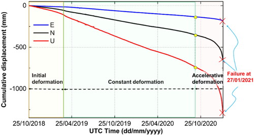
The landslide at the HF09 monitoring station experienced three evolutionary stages since the beginning of the monitoring period based on the GNSS monitoring results. According to the three-stage theory (Xu et al. Citation2009), these stages can be divided into the initial deformation stage (October 2018 to March 2019), constant deformation stage (April 2019 to November 2020), and last stage of accelerated failure (December 2020 to January 2021) (). The deformation of the HF09 monitoring station was monitored and significant acceleration was detected by the intelligent monitoring and early warning cloud platform on 23 December 2020. The monitoring system issued a yellow alert when the deformation rate in the three-dimensional direction reached 5.3 mm/d, and the cumulative displacement reached 1011.2 mm. The landslide entered the stage of accelerated failure according to the three-stage theory of landslide creep and the improved tangential angle criterion (Fan et al. Citation2019; Xu et al. Citation2009). The landslide warning information had to be accurately provided since the residential zones were less than 500 meters from the landslide. The area of the landslide front was the position where the deformation was greatest and where land mass began to slide first. Although monitoring data in this area is crucial for real-time alerts, no monitoring equipment was available at the landslide front.
Figure 9. Time series of GNSS landslide monitoring station HF09 in the east (E), North (N), and upward (U) directions are represented by blue, black, and red lines, respectively. The yellow circles indicate that the landslide has entered the accelerated deformation stage. The landslide experienced three stages, including the initial deformation, constant deformation, and accelerative deformation stages from 25 october 2018 to 27 January 2021.
3.3. Experimental procedure
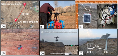
Our research team visited Heifangtai to test the GNSS equipment deployed by the UAV from 26 December to 27 December 2020. A new GNSS monitoring station (BP01) was deployed at the landslide front using a UAV. The drop site of BP01 (36°05′31.71″ N, 103°18′42.42″ E) was 3 m from HF09 and closer to the landslide front (). The drop site was located at a height of approximately 1671.8 m, approximately 135 m higher than the UAV take-off location. Additionally, the drop height was 2 m above the ground, the horizontal drop distance was approximately 414 m, and the ambient test temperature ranged from −5 °C to 5 °C. The flight duration did not exceed 18 min ().
Figure 10. Field deployment test of unmanned aerial vehicle (UAV)-dropped global navigation satellite system (GNSS) monitoring equipment. (a) Location of the UAV take-off point and UAV drop site. (b) Assembly of the equipment on-site. (c) Appearance and internal structure of UAV-dropped GNSS equipment (UDGE). (d) environment of the UAV take-off point. (e) Accurately determining the drop point. (f) Relative positions of BP01 and HF09.
4. Results and discussion
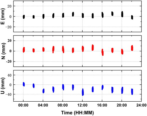
We conducted six experiments over two days, three of which successfully installed GNSS equipment to the landslide surface. The observation time was set using the cloud platform, to 10 min every 2 h after the deployment of the GNSS. Data processing was conducted utilizing dual-frequency measurement data from both GPS and BDS. The single-day monitoring time series of BP01 for day 363 of the year 2020 (UTC) is displayed in . The ambiguity fixed rate of the RTK solutions was 100%, and the standard deviations in the east (E), north (N), and upward (U) directions were 2, 3, and 10 mm, respectively.
Figure 11. Single-day GNSS monitoring time series of BP01 (day 363 of 2020 in UTC).
The GNSS deformation monitoring data of the traditional monitoring station HF09 and the UAV-dropped monitoring station BP01 were simultaneously observed during the landslide. A comparison of the monitoring time series in the E, N, U direction is shown in . The horizontal distance between HF09 and BP01 was only 3 m; therefore, the monitoring data of HF09 were used as a reference for the data quality evaluation of BP01. HF09 was set to collect continuous observation data for a 1 Hz sampling rate of 24 h with no interruption, whereas BP01 was set to collect observation data for 10 min every 2 h.
Figure 12. Comparison of time series and deformation rate in the E, N, and U direction of the BP01 and HF09 monitoring stations. The data represents a 31-day period from 27 december 2020 to 27 January 2021.
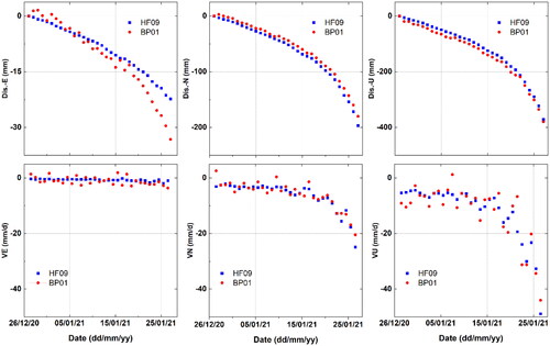
The deformation trends of BP01 and HF09 were relatively the same, which preliminarily verifies the feasibility of adopting UAV-dropped GNSS technology for landslide monitoring (). The landslide deformation velocities, monitored daily from BP01 and HF09, were compared using the mean absolute error (MAE). The MAE is a measure of the error between pairs of observations that represent the same phenomenon and, therefore, was an appropriate means to evaluate the monitoring precision of the UAV-dropped station BP01. The MAE method is expressed by EquationEquation (5)(5)
(5) :
(5)
(5)
where
and
denote the average daily deformation rates (mm/d) of BP01 and HF09, respectively, and
is the number of monitoring days, which was 30 in this study. The average
of these 30 days in E, N, and U directions were 1.2, 1.3, and 2.9 mm/d, respectively. Comparing their difference in velocity, the maximum error occurred on 22 January, with a difference of 12.4 mm/d in the U direction. The recorded velocity rates were necessarily different because the monitoring positions of BP01 and HF09 differed. Additionally, the data quality of the two monitoring stations differed as each station used different satellite antennas, with varying degrees of accuracy. However, the primary cause of the difference in the observed velocity rates was the insufficient power supply for the BP01 monitoring station from 22 January to 24 January, resulting in the loss of observation data on 23 January and incomplete observation data on 22 January and 24 January.
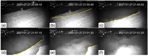
Based on a comprehensive analysis of the monitoring sequences of the HF09 and BP01 monitoring stations, several levels warning messages were continuously issued by the ‘Landslide Hazard Monitoring and Early Warning System’ before the landslide occurred. An orange alert was issued four days before the landslide occurred () (Huang et al. Citation2022) and a red alert was issued 6 h before the landslide occurred. In addition, emergency alert information of the imminent failure of the landslide was issued 7 min before the landslide occurred (). Owing to timely alerts, casualties were avoided. The scope of the landslide is shown in . The sliding process of the landslide was photographed using an infrared night-vision instrument (). The time stamps shown in the photos are recorded in China Standard Time.
Figure 13. Early warning messages and image of the landslide. (a) Orange alert message was issued using chinese languages. [chang’an university, orange early warning alerts]. on january 23, 2021, at 11:00 China standard time (CST), the landslide warning system issued an orange alert to the landslide area in heifangtai, yanguoxia town, yongjing country, China: ‘the cumulative displacement and the deformation rate of the HF09 station were 1294.5 and 25.9 mm/d’, respectively, in three dimensions. (b) Red alert message ‘please be ready to avert disasters’ was issued using chinese language. [chang’an university, red early warning alerts]. on january 27, 2021, at 14:00 CST, the landslide warning system issued a red alert ‘please be ready to avert disasters’ to the landslide area in heifangtai, yanguoxia town, yongjing country, China: ‘the cumulative displacement and the rate of deformation of the HF09 station are 1445.4 and 68.7 mm/d’, respectively, in three dimensions. (c) Image of the dangchuan landslide. The disaster zone of the landslide is indicated by the red enclosure. The red arrows indicate the sliding direction of the landslide.
![Figure 13. Early warning messages and image of the landslide. (a) Orange alert message was issued using chinese languages. [chang’an university, orange early warning alerts]. on january 23, 2021, at 11:00 China standard time (CST), the landslide warning system issued an orange alert to the landslide area in heifangtai, yanguoxia town, yongjing country, China: ‘the cumulative displacement and the deformation rate of the HF09 station were 1294.5 and 25.9 mm/d’, respectively, in three dimensions. (b) Red alert message ‘please be ready to avert disasters’ was issued using chinese language. [chang’an university, red early warning alerts]. on january 27, 2021, at 14:00 CST, the landslide warning system issued a red alert ‘please be ready to avert disasters’ to the landslide area in heifangtai, yanguoxia town, yongjing country, China: ‘the cumulative displacement and the rate of deformation of the HF09 station are 1445.4 and 68.7 mm/d’, respectively, in three dimensions. (c) Image of the dangchuan landslide. The disaster zone of the landslide is indicated by the red enclosure. The red arrows indicate the sliding direction of the landslide.](/cms/asset/ebecee35-36a0-4c64-9097-2fdfcf6e850c/tgnh_a_2366374_f0013_c.jpg)
Figure 14. Cracking process of the landslide captured by surveillance video. (a–f) Sliding processes experienced by the landslide. The time stamps shown in the photos are recorded in CST.
The experimental environment for this experiment was suitable, and the target point was on a relatively flat loess ground. However, the success rate of equipment deployment using UAV was only 50%. These experimental results highlighted the importance of continuous innovation in dropping the GNSS equipment on the surface stably and safely. We have designed other UDGEs and fixed technologies that require more experimentation and improvement. Reconnaissance and transportation UAV operations are still entirely manual and not yet automated. Fortunately, automation can be achieved by finding partners and integrating existing technologies. Unfortunately, we have found that communication between UAVs and our control platform is easily interrupted due to physical obstruction, which makes it difficult for us to control and monitor the condition of UAVs during task execution in real time. Therefore, the communication technology that can ensure data transmission between our UDGE devices, UAVs, and cloud control platforms is currently being developed.
5. Conclusions
In this study, we proposed the development of a GNSS landslide monitoring technology deployed by a UAV. Our results provide a novel technology to address the difficulty of deploying contact monitoring techniques and the high-risk of on-site personnel deployment in HRDA landslide scenarios. The main conclusions are summarized as follows:
An adaptive sampling GNSS receiver with low energy consumption was developed, which can be triggered to work through a cloud platform or terminal. The 24-h continuous data acquisition mode of the traditional GNSS receiver was replaced with a variable mode for obtaining observation data.
A lightweight GNSS equipment that can be dropped by an UAV was developed. The device integrates a low-energy adaptive sampling GNSS receiver, power supply system, and other functional modules. A matching GNSS deployment scheme using a UAV was planned.
The UAV-dropped GNSS technology was first applied to monitor the Dangchuan landslide in the Heifangtai region on 27 December 2020. Some critical alert messages were successfully issued before the landslide occurred on 27 January 2021. By comparing the UAV-dropped GNSS monitoring station BP01 with the traditional monitoring station HF09, the MAE in the directions E, N, and U for 30 days were 1.2, 1.3, and 2.9 mm/d, respectively, thereby demonstrating good consistency.
Research on UAV-dropped GNSS landslide monitoring technology will provide a theoretical basis for the development of real-time landslide monitoring from ‘manned deployment’ to ‘unmanned deployment’. This technology has broad application prospects in mountainous and gorge areas with frequent, high-risk geological disasters, such as Tibet, Sichuan, and Yunnan in southwest China. In the future, the development of robot, vision, and intelligent technologies will further promote the development and improvement of GNSS unmanned deployment technology.
Author’s contributions
QZ and ZB proposed the initial idea; ZB and GH wrote the manuscript. JK provided geological data resources. ZB contributed to the experiments by performing them and analyzing the data. GH, YD, CJ and DW helped improve the manuscript, WX enhanced the language. The final manuscript has been read and approved by all writers.
Acknowledgements
The authors appreciate the editors’ and the anonymous reviewers’ helpful criticism of this work.
Availability of data and materials
Data requests can be made to the corresponding author via this email: [email protected]
Disclosure statement
The authors declare that they have no competing of interests.
Additional information
Funding
References
- Auflič MJ, Herrera G, Mateos RM, Poyiadji E, Quental L, Severine B, Peternel T, Podolszki L, Calcaterra S, Kociu A, et al. 2023. Landslide monitoring techniques in the Geological Surveys of Europe. Landslides. 20(5):951–965. Maydoi: 10.1007/s10346-022-02007-1.
- Bai Z, Huang G, Zhang Q, Jing C, Wang D. 2024. An integer ambiguity resolution method based on baseline vector predictions in landslide monitoring. Measurement. 229:114363. doi: 10.1016/j.measurement.2024.114363.
- Bai Z, Zhang Q, Huang G, Jing C, Wang J. 2019. Real-time BeiDou landslide monitoring technology of light terminal plus industry cloud. Acta Geodetica et Cartographica Sin. 48:1424–1429.
- Bian S, Chen G, Zeng R, Meng X, Jin J, Lin L, Zhang Y, Shi W. 2022. Post-failure evolution analysis of an irrigation-induced loess landslide using multiple remote sensing approaches integrated with time-lapse ERT imaging: lessons from Heifangtai, China. Landslides. 19(5):1179–1197. doi: 10.1007/s10346-022-01859-x.
- Casagli N, Intrieri E, Tofani V, Gigli G, Raspini F. 2023. Landslide detection, monitoring and prediction with remote-sensing techniques. Nat Rev Earth Environ. 4(1):51–64. doi: 10.1038/s43017-022-00373-x.
- Cenni N, Fiaschi S, Fabris M. 2021. Integrated use of archival aerial photogrammetry, GNSS, and InSAR data for the monitoring of the Patigno landslide (Northern Apennines, Italy). Landslides. 18(6):2247–2263. doi: 10.1007/s10346-021-01635-3.
- Chang W, Xing A, Wang P, Zhuang Y, Jin K, He J, Chai S. 2021. Analysis of Dangchuan 5# landslide on January 27, 2021, in Yongjing County, Gansu Province, China. Landslides. 18(11):3615–3628. doi: 10.1007/s10346-021-01743-0.
- Cui P, Ge Y, Li S, Li Z, Xu X, Zhou GGD, Chen H, Wang H, Lei Y, Zhou L, et al. 2022. Scientific challenges in disaster risk reduction for the Sichuan-Tibet Railway. Eng Geol. 309:106837. doi: 10.1016/j.enggeo.2022.106837.
- Fan X, Xu Q, Liu J, Subramanian SS, He C, Zhu X, Zhou L. 2019. Successful early warning and emergency response of a disastrous rockslide in Guizhou province, China. Landslides. 16(12):2445–2457. Decdoi: 10.1007/s10346-019-01269-6.
- Fan X, Xu Q, Scaringi G, Li S, Peng D. 2017. A chemo-mechanical insight into the failure mechanism of frequently occurred landslides in the Loess Plateau, Gansu Province, China. Eng Geol. 228:337–345. doi: 10.1016/j.enggeo.2017.09.003.
- Gu T-f, Zhang M-s, Wang J-d, Wang C-x, Xu Y-j, Wang X. 2019. The effect of irrigation on slope stability in the Heifangtai Platform, Gansu Province, China. Eng Geol. 248:346–356. doi: 10.1016/j.enggeo.2018.10.026.
- Hou X, Vanapalli SK, Li T. 2019. Wetting-induced collapse behavior associated with infiltration: a case study. Eng Geol. 258:105146. doi: 10.1016/j.enggeo.2019.105146.
- Huang G, Du S, Wang D. 2023. GNSS techniques for real-time monitoring of landslides: a review. Satell Navig. 4(1):5. doi: 10.1186/s43020-023-00095-5.
- Huang G, Wang D, Du Y, Zhang Q, Bai Z, Wang C. 2022. Deformation feature extraction for GNSS landslide monitoring series based on robust adaptive sliding-window algorithm. Front Earth Sci. 10:884500. doi: 10.3389/feart.2022.884500.
- Jing C, Huang G, Li X, Zhang Q, Yang H, Zhang K, Liu G. 2023. GNSS/accelerometer integrated deformation monitoring algorithm based on sensors adaptive noise modeling. Measurement. 218:113179. doi: 10.1016/j.measurement.2023.113179.
- Kong J-x, Zhuang J, Q, Zhan J-w, Bai Z-w, Leng Y-q, Ma P-h, Peng J-b, Wang Z-p, Gu T-f, Sun J-x, et al. 2021. A landslide in Heifangtai, northwest of the Chinese Loess Plateau: triggered factors, movement characteristics, and failure mechanism. Landslides. 18(10):3407–3419. doi: 10.1007/s10346-021-01752-z.
- Lee H-C, Ke K-H, Fang Y-M, Lee B-J, Chan T-C. 2017. Open-source wireless sensor system for long-term monitoring of slope movement. IEEE Trans Instrum Meas. 66(4):767–776. Aprdoi: 10.1109/TIM.2017.2657838.
- Liu X, Zhao C, Zhang Q, Yang C, Zhu W. 2020. Heifangtai loess landslide type and failure mode analysis with ascending and descending Spot-mode TerraSAR-X datasets. Landslides. 17(1):205–215. Jandoi: 10.1007/s10346-019-01265-w.
- Lu C, Cai C. 2019. Challenges and countermeasures for construction safety during the Sichuan-Tibet railway project. Engineering. 5(5):833–838. doi: 10.1016/j.eng.2019.06.007.
- Rodriguez J, Deane E, Macciotta R, Evans T, Gräpel C, Skirrow R. 2021. Practical evaluation of single-frequency dGNSS for monitoring slow-moving landslides. Landslides. 18(11):3671–3684. doi: 10.1007/s10346-021-01737-y.
- Shi X, Xu Q, Zhang L, Zhao K, Dong J, Jiang H, Liao M. 2019. Surface displacements of the Heifangtai terrace in Northwest China measured by X and C-band InSAR observations. Eng Geol. 259:105181. doi: 10.1016/j.enggeo.2019.105181.
- Shugar DH, Jacquemart M, Shean D, Bhushan S, Upadhyay K, Sattar A, Schwanghart W, McBride S, de Vries MVW, Mergili M, et al. 2021. A massive rock and ice avalanche caused the 2021 disaster at Chamoli, Indian Himalaya. Science. 373(6552):300–306. doi: 10.1126/science.abh4455.
- Silvagni M, Tonoli A, Zenerino E, Chiaberge M. 2017. Multipurpose UAV for search and rescue operations in mountain avalanche events. Geomatics Nat Hazards Risk. 8:18–33.
- Wang D, Huang G, Du Y, Zhang Q, Bai Z, Tian J. 2023. Stability analysis of reference station and compensation for monitoring stations in GNSS landslide monitoring. Satell Navig. 4(1):29. doi: 10.1186/s43020-023-00119-0.
- Xu Q, Zeng YP, Qian JP, Wang CJ, He CJ. 2009. Study on a improved tangential angle and the corresponding landslide pre-warning criteria. Geol Bull China. 28(4):501–505.
- Xu Q, Zhao B, Dai K, Dong X, Li W, Zhu X, Yang Y, Xiao X, Wang X, Huang J, et al. 2023. Remote sensing for landslide investigations: a progress report from China. Eng Geol. 321:107156. Augdoi: 10.1016/j.enggeo.2023.107156.
- Xu Q. 2020. Understanding the landslide monitoring and early warning: consideration to practical issues. J Eng Geol. 28:360–374.
- Zhang F, Huang X. 2018. Trend and spatiotemporal distribution of fatal landslides triggered by non-seismic effects in China. Landslides. 15(8):1663–1674. Augdoi: 10.1007/s10346-018-1007-z.
- Zhang F, Peng J, Huang X, Lan H. 2021. Hazard assessment and mitigation of non-seismically fatal landslides in China. Nat Hazards. 106(1):785–804. doi: 10.1007/s11069-020-04491-x.
- Zhang F, Wang G. 2018. Effect of irrigation-induced densification on the post-failure behavior of loess flowslides occurring on the Heifangtai area, Gansu, China. Eng Geol. 236:111–118. doi: 10.1016/j.enggeo.2017.07.010.
- Zhang Q, Bai Z, Huang G, Du Y, Wang D. 2022. Review of GNSS landslide monitoring and early warning. Acta Geodetica et Cartographica Sin. 51:1985–2000.
- Zhang S, Pei X, Wang S, Huang R, Zhang X, Chang Z. 2019. Centrifuge model testing of a loess landslide induced by rising groundwater in Northwest China. Eng Geol. 259:105170. doi: 10.1016/j.enggeo.2019.105170.