ABSTRACT
The design of optimum spiral casing configuration is a difficult task and a big challenge in the field of turbomachinery. Computational fluid dynamics (CFD) analysis of fluid flow characteristics in a turn around spiral casing plays an important role in its design. The objective in this study is to propose an optimum spiral casing configuration by reducing the total pressure loss and increasing the spiral velocity coefficient and average radial velocity at the exit of spiral casing. For this, three different configurations of spiral casing, viz. accelerated, decelerated and free vortex type, with different aspect ratios (ARs) are numerically simulated. A Eulerian velocity-correction method based on the streamline upwind Petrov–Galerkin (SUPG) finite-element method is employed to solve complete Reynolds-averaged Navier–Stokes (RANS) equations governing fluid flow characteristics. The results show that the average radial velocity along the exit of spiral casings is more for elliptical cross-sectional spiral casings of AR>1 when compared to circular cross-sectional spiral casings. The total pressure loss is found to be at minimum for decelerated spiral casings. In the case of decelerated spiral casings, a further reduction in total pressure loss is obtained with elliptical cross-sections of AR>1. The spiral velocity coefficient is found to be at maximum for decelerated spiral casings with AR>1.
1. Introduction
Hydropower is a clean, renewable energy as it requires only water. It is one of the largest sources of renewable energy and the most efficient way to generate electricity. About of the world's electrical energy is generated through the use of hydropower (Ingram, Citation2009). The hydraulic turbine converts the kinetic energy of water into electrical energy through a generator. Of all the hydraulic turbines used for the generation of electrical energy, the Francis turbine is the most widely employed turbine in the world for large-scale hydropower stations. Knowledge about the internal flow field is required for the further development of hydraulic turbines. With great advances in computational fluid dynamics (CFD) and a rapid increase in computing capacity, the numerical simulation of Navier–Stokes equations is evolving as an advanced technique in the field of turbomachinery. Experimental methods of predicting the performance of turbomachines are time-consuming and expensive compared to the CFD approach, which is now widely used in the fluid flow simulation of turbomachines (Danish, Khan, Umer, Qureshi, & Ma, Citation2014; Galindo, Hoyas, Fajardo, & Navarro, Citation2013; Gareev, Kosasih, & Cooper, Citation2013; Liu, Wang, Wang, Huang, & Jiang, Citation2014).
Fluid flow through Francis turbine components such as the spiral casing, stay vanes, guide vanes, runner and draft tube has been studied extensively in the literature. Unsteady hydraulic behaviors such as pressure fluctuations and vibration for a large Francis turbine over part load conditions have been investigated in site tests by Wang, Li, Ma, Yang, and Zhu (Citation2009). Susan-Resiga, Muntean, Avellan, and Anton (Citation2011) mathematically modeled the swirling flow in hydraulic turbines for the full operating range corresponding to different discharges. Recently, experimental and numerical studies for a high head Francis turbine were carried out over the entire range of turbine operation (Trivedi, Cervantes, Gandhi, & Dahlhaug, Citation2013). The runner is the only rotating component of the Francis turbine, the flow through which is complex in nature. Runner blades are the centers which the fluid strikes and the impact causes the shaft of the turbine to rotate, hence producing electrical power. High Reynolds number turbulent flow in strongly 3D skew blade passages of a Francis turbine was simulated by L.-X. Zhang, Wang, and Guo (Citation2007) using the large eddy simulation approach. From this study, spatial and temporal distributions of the fully developed turbulence were investigated. The spatial and temporal distribution of the turbulent flow in the blade passage is non-uniform. Flow-induced stresses in a Francis turbine runner were numerically analyzed by Saeed, Galybin, and Popov (Citation2010) and Negru, Muntean, Marsavina, Susan-Resiga, and Pasca (Citation2012). In these studies, the results of large-scale modeling of the water flow and analysis of flow-induced stresses in a Francis turbine runner are shown. The draft tube is another important component which connects the runner exit to the tail race where the water is finally collected from the turbine. The purpose of the draft tube is to reduce the velocity of the discharged water, thereby minimizing the kinetic energy loss at the outlet. Marjavaara and Lundstrom (Citation2006) optimized the shape of an existing sharp heel draft tube and validated the results with previously performed experiments. They used response-surface methodology as a shape-optimization technique for maximizing the average pressure recovery factor and minimizing the energy loss factor. The dynamics of the rotating vortex which forms in the draft tube of a Francis turbine for partial flow rate operating conditions were studied by carrying out both an experimental flow survey and numerical simulations (Ciocan, Iliescu, Vu, Nennemann, & Avellan, Citation2007). Recently, the swirling flow in a Francis turbine draft tube was experimentally analyzed by Tridon, Barre, Ciocan, and Tomas (Citation2010). In their study, radial, axial and tangential velocities were measured and validated with analytical results for determining the accuracy of measurements.
The spiral casing of a hydraulic turbine is a passage with a turn. The function of the spiral casing in a Francis turbine is to distribute the water as evenly as possible to the stay and guide vanes (distributor) and then to the turbine runner. Stay vanes are used to stabilize the flow regime and guide vanes are used to control the flow rate and, consequently, the power generated by the turbine. The flow through the distributor for various boundary conditions with different configurations was analyzed by Dadfar, Firoozabadi, and Ahmadi (Citation2010). Their study revealed that the presence of runner blades under design conditions has minor effects on the pressure field around the stay and guide vane. In an efficiently designed spiral casing, the pressure head of the fluid is available to the runner with minor losses. Therefore, the analysis of fluid flow through a spiral casing with regard to minimum pressure loss is very much essential. Shyy and Vu (Citation1991) conducted a study to predict the fluid flow structure and losses in various sections of the turbine. In their investigation, Reynolds-averaged Navier–Stokes (RANS) equations, closed with the k-
turbulence model (Launder & Spalding, Citation1974), were solved for high Reynolds numbers. The energy losses which take place in all the components of hydraulic turbines mainly occur due to flow separation, secondary flow, wall friction, etc. Some experimental studies state that the hydraulic loss in a spiral casing depends on the formation of secondary flow. Flow curvature and viscous forces are the main sources for the generation of secondary flow in spiral casings, as experimentally observed by Kurokawa and Nagahara (Citation1986). The failure of the Dartmouth turbine casing due to the stresses and fracture mechanics caused by fluid hammer was studied by Price (Citation1998). The flow-induced structural vibrations affecting the spiral casing structure of a large-scale hydropower plant was successfully simulated by Li and Zhang (Citation2012). Recently, L. Zhang, Ren, Li, and Chen (Citation2012) studied methods to reduce hydraulic loss in spiral casings, concluding that there is less hydraulic loss in spiral casings and stay rings with no stay vanes than those with stay vanes.
Kurokawa and Nagahara (Citation1986) theoretically and experimentally studied the fluid flow in different types of spiral casing, viz. accelerated, decelerated and free vortex, to determine the optimum spiral-casing configuration. In the accelerated type, the cross-sectional area in the first half of the spiral is made as small as possible in order to obtain a high tangential velocity. In the decelerated type, the reduction rate of the cross-sectional area is made as small as possible in the first half of the spiral in order to obtain a smooth change of flow pattern from the straight cylinder flow to the free-vortex flow. The free-vortex type of spiral casing is widely used; Kurokawa and Nagahara (Citation1986) concluded that the optimum configuration can be achieved by reducing the tangential velocity in a spiral casing. All of the experiments conducted by Kurokawa and Nagahara (Citation1986) were restricted to circular cross-sections only. The fluid flow through spiral casings was numerically simulated by Maji and Biswas (Citation1998, Citation1999) using a finite-element method. In their studies, the velocity field, pressure distribution and behavior of secondary flow inside the spiral casing are presented in detail. Maji and Biswas (2000) simulated the fluid flow through the plate-spiral of a reaction turbine using the streamline upwind Petrov-Galerkin (SUPG; Brooks & Hughes, Citation1982) finite-element method. In this study, flow structure and pressure drop characteristics in a plate-spiral were predicted. All of the simulations in Maji and Biswas (Citation1998, Citation1999, Citation2000) were limited to the free-vortex type of spiral casing with a circular cross-section. Spiral casings with elliptical cross-sections and bell-mouth-type stay rings were compared with spiral casings with circular cross-sections and rectangular-type stay rings by Desai, Chauhan, Roghelia, and Soni (Citation2010), who concluded that the performance of spiral casings with elliptical cross-sections is better compared to those with circular cross-sections. However, their research was restricted to a single type of spiral casing with only one type of elliptical cross-section.
To the best of the authors' knowledge, a detailed study of the fluid flow characteristics of different configurations of spiral casing (accelerated, decelerated and free vortex) with different elliptical and circular aspect ratios (ARs) has not been reported, and thus this is the aim of the present study. The effects of elliptical and circular cross-sections on flow parameters in different configurations of spiral casing are numerically studied for predicting the total pressure loss, spiral velocity coefficient and average radial velocity at the distributor exit. Based on these results, an optimum configuration is proposed.
2. Mathematical modeling
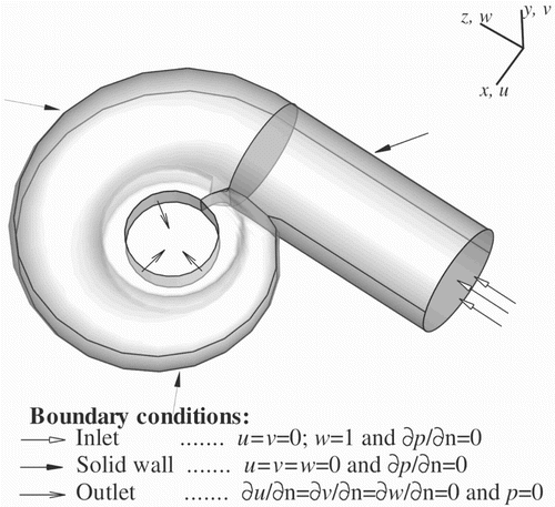
The computational domain under investigation is a three-dimensional spiral casing consisting of two parts such as a straight cylindrical part and a spiral part (Figure ). In the spiral casing, the fluid flow from the cylindrical part is converted from a straight flow into a curved flow. The distributor zone is placed at the circumferential exit of the spiral casing consisting of airfoils. These airfoils control the mass flow rate of the water. It is difficult and unnecessary to take into account the effect of every individual airfoil (Maji & Biswas, Citation1998). Therefore, in the present problem the distributor zone is created as porous media in which the effect of individual airfoils is not considered. Variation in the cross-sectional area along the circumferential direction in different configurations (accelerated and decelerated) is taken from Kurokawa and Nagahara (Citation1986), and the free-vortex configuration is taken from Maji and Biswas (Citation1998). The fluid used in the present work is water. The Reynolds number (Re) based on the inlet diameter used in the present study is . The fluid flow is turbulent, incompressible and viscous. The domain is discretized into linear hexahedral elements of small size. The pressure and velocity components are calculated at every node. RANS equations with an extra term indicating the porous media treatment based on Darcy's law are solved. These equations, together with mass conservation equation, are written in Cartesian tensor form as:
(1)
(2)
where the subscripts i and j can take the values 1, 2 and 3 in three coordinate directions,
,
and
are the x, y and z of Cartesian coordinates, respectively, and the velocity components
,
and
are the u, v and w, respectively. The equations are written in dimensionless form. Here:
where D is the characteristic length, ν is the kinematic viscosity and
is the inlet velocity. The turbulent viscosity
is given by Prandtl's mixing length model as
(3) where
is taken as
, and δ is the dimensionless radius of the duct at any cross-section and λ is a fixed value (taken as 0.085). The variables
,
, τ and p are non-dimensionalized using the dimensional variables D,
,
and
, respectively. Here, K is the non-dimensionalized Darcy's coefficient and its value indicates the resistance offered by the distributor region. In the present study, an in-house finite-element algorithm is used to solve RANS equations. The solution algorithm uses a Eulerian velocity-correction approach that is based on the projection scheme of Chorin (Citation1967), which was initially developed in a finite-difference context and is also incorporated in the Marker and cell (MAC) method of Harlow and Welch (Citation1982). It was extended to a two-dimensional finite-element method by Donea, Giuliani, Laval, and Quartapelle (Citation1982). The algorithm in the present study is applied to the solution of the turbulent flow in a three-dimensional domain. The solution algorithm and finite-element formulation are explained in Prakash, De, Kumar, and Biswas (Citation2006). The same algorithm has also been applied to different applications, such as nuclear engineering (Prakash, Biswas, & Kumar, Citation2006), electronic cooling (Lam & Prakash, Citation2014) and fuel cells (Ravishankar & Prakash, Citation2014). Standard Galerkin finite-element methods for convection diffusion problems produce an oscillatory solution when convection dominates over diffusion. To overcome this problem, the SUPG technique (Brooks & Hughes, Citation1982) is used in the formulation. It is based on the notion that upwind biasing is effectively equivalent to the introduction of an artificial diffusion in the flow direction. In this formulation the test functions and the trail functions are from different classes of functional space. In a standard Galerkin's weighted residual method, the test functions are continuous across inter-element boundaries. However, the SUPG formulation requires discontinuous test functions of the form
, where
is a weighting function which is continuous and
is a streamline upwind contribution which is discontinuous.
3. Code validation
Grid sensitivity analysis was carried out to ensure that the numerical algorithm is independent of the mesh. The present numerical algorithm has been well validated with standard benchmark problems such as lid-driven cavity, backward-facing step and buoyancy-driven cavity (Prakash, De, et al., Citation2006). The present solution algorithm was applied to bend problems (Prakash, Biswas, & Kumar, Citation2006; Ravishankar & Prakash, Citation2015), with good results. The present numerical algorithm was also applied to a fuel cell stack problem (Ravishankar & Prakash, Citation2014), in which the fluid takes several turns.
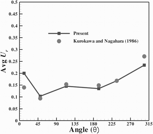
The average radial velocity along the section VV for the accelerated type of spiral casing is compared with the experimental results of Kurokawa and Nagahara (Citation1986) in Figure . For this validation, the numerical simulation was performed at Re for the accelerated type of spiral casing. The average radial velocity is quantitatively in good agreement with the experimental results of Kurokawa and Nagahara (Citation1986).
Figure 2. Comparison of the average radial velocity along the section VV for the accelerated type of spiral casing.
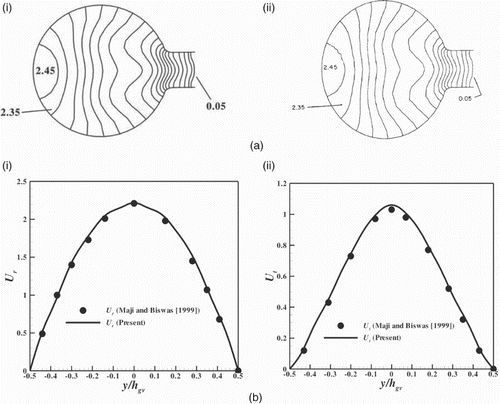
The numerical algorithm was also validated with the results of Maji and Biswas (Citation1998) (Figure ). The present simulation was performed at Re and Darcy's coefficient (K) along the distributor zone was used in a similar way to that of Maji and Biswas (Citation1999). The static pressure (P) contours of the spiral casing at the
cross-section are compared in Figure (a) and found to be in good agreement with Maji and Biswas (Citation1999). The distribution of the radial velocity (
) and tangential velocity (
) along the section GG at the
cross-section for the free-vortex type of spiral casing is also compared with Maji and Biswas (Citation1999) (Figure (b)). Both the velocity distributions (
and
) are quantitatively in good agreement with the numerical results of Maji and Biswas (Citation1999).
Figure 3. Comparison of (a) static pressure contours for (i) the present study and (ii) Maji and Biswas (Citation1999), and (b) the values at the cross-section for (i) the radial velocity and (ii) the tangential velocity.
4. Results and discussion
The fluid flow through different types of spiral casings with various ARs is numerically investigated in the present study. The static pressure, radial velocity, tangential velocity, average radial velocity at the exit and total pressure loss are determined for all configurations with various ARs in order to find the best configuration.
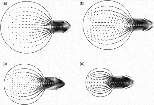
Secondary flow behavior in cross-sections of the decelerated type of spiral casing are shown in Figure . Various factors like curvature, the continuous reduction of a cross-sectional area in a circumferential direction of the spiral casing, the no-slip boundary along the walls and the opening at the exit in a circumferential direction are some of the important parameters that affect the generation of secondary flow. At the start of the casing section (Figure (a)), the fluid flows evenly along the height of the casing. Secondary flow occurs as twin vortices at the center of the cross-section (Figure (b) and (c)) due to an imbalance between the radial pressure gradient and the centrifugal force. The strength of the secondary flow changes from one cross-section to another, existing even after a turn (Figure (c)), at which point the twin vortices are weaker. The twin vortices disappear after the
turn (Figure (d)). The secondary flow on the cross-stream planes also exists for other types of spiral casing, and its behavior is the same as that of the secondary flow in the decelerated type of spiral casing.
Figure 4. Behavior of the secondary flow on the cross-stream planes of the decelerated type of spiral casing at (a) , (b)
, (c)
and (d)
. Note: The length of the vector represents the magnitude of the velocity and the direction of the vector indicates the orientation of the flow.
4.1. Comparison of different configurations of spiral casing
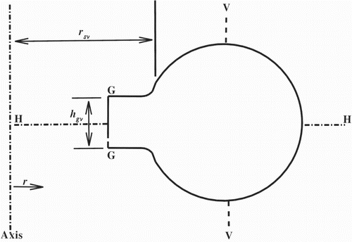
The zones on a cross-section of a spiral casing are shown in Figure . Variation in the fluid flow parameters in section HH indicates variation in the radial direction. Section GG represents the exit of the spiral casing. Variation in the fluid flow parameters in section VV indicates variation in the vertical direction, which is parallel to the turbine axis. The effect of the spiral casing configuration on the static pressure, radial velocity and tangential velocity distribution in sections HH, VV and GG at and
turn cross-sections is shown in Figures –.
Figure 6. Distribution of (a) the static pressure, (b) the radial velocity and (c) the tangential velocity in section HH in different configurations of spiral casing for turn cross-sections at (i) and (ii)
.
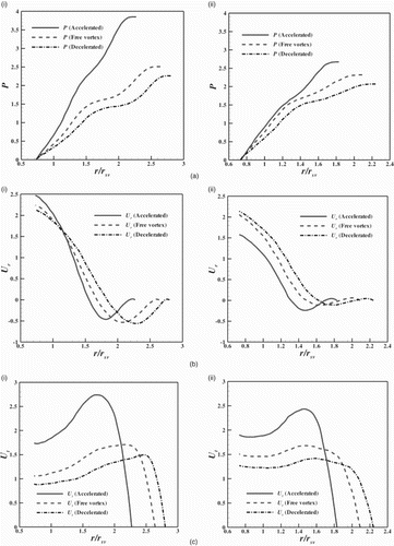
Figure 7. Distribution of (a) the static pressure, (b) the radial velocity and (c) the tangential velocity in section VV in different configurations of spiral casing for turn cross-sections at (i) and (ii)
.
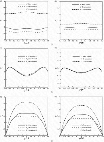
Figure 8. Distribution of (a) the radial velocity and (b) the tangential velocity in section GG in different configurations of spiral casing for turn cross-sections at (i)
and (ii)
.
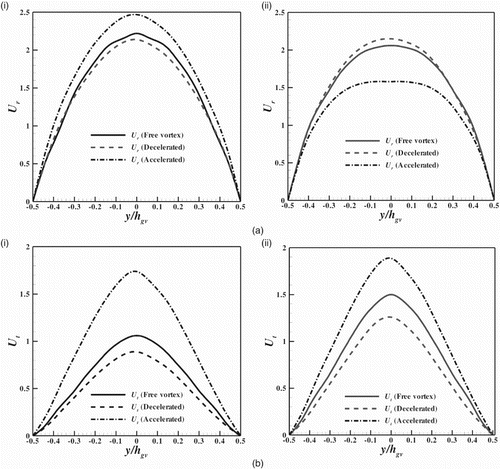
The static pressure (P) is high near the wall and generally decreases towards the distributor exit (Figure (a)). This decrease in static pressure helps the fluid to accelerate in the distributor zone. It can be seen that the static pressure near the wall decreases in the circumferential direction in all configurations. The static pressure reduction near the wall is greater in the accelerated type of spiral casing than in the free-vortex and decelerated types. The distribution of the radial velocity () in section HH is shown in Figure (b). The negative
indicates the outward flow due to secondary flow. The radial velocity accelerates in the distributor region and is found to be greater in the accelerated type of spiral casing at the
turn cross-section near the distributor exit. The radial velocity is found to be less in the accelerated type of spiral casing at the
turn cross-section near the distributor exit. The
value is slightly increased near the distributor exit in the decelerated type and slightly decreased in the free-vortex type at the
turn cross-section. The variation of the tangential velocity (
) in section HH is shown in Figure (c). The tangential velocity accelerates from the outer wall in the direction of the inner radius up to some distance and becomes low within the distributor. It can be seen that the tangential velocity is high in the accelerated type of spiral casing and low in the decelerated type. The high tangential velocity in section HH in the accelerated type of spiral casing is due to the presence of a large pressure gradient (Figure (a)). The tangential velocity near the distributor exit increases in the circumferential direction in all configurations.
There is no significant variation of static pressure in section VV (Figure ). The static pressure in section VV is greater in the accelerated type of spiral casing and less in the decelerated type (Figure (a)). The P in VV decreases in the accelerated type of spiral casing in the circumferential direction and increases slightly in the other configurations. The pattern of radial velocity distribution is similar in all configurations (Figure (b)). The negative area indicates outward flow and the positive area indicates inward flow. The radial velocity distribution indicates that outward flow is generated at the center and inward flow is induced close to the walls. The outward flow induced at the center is due to the secondary flow induced on the cross-stream plane. As the inward flow is almost identical in all configurations and the outward flow is less in the accelerated type of spiral casing, the effect of the secondary flow is less in the accelerated type of spiral casing at the turn cross-section. From Figure (b), it can be seen that the effect of the secondary flow reduces in the circumferential direction due to the reduction in outward flow. The distribution of the tangential velocity in different configurations of spiral casing is depicted in Figure (c). The tangential velocity in section VV is found to be greater in the accelerated type of spiral casing and less in the decelerated type. It can be seen that the tangential velocity in section VV decreases in the circumferential direction in all configurations.
The radial velocity distribution pattern in section GG is similar in all configurations (Figure (a)). The magnitude of the radial velocity is high in the accelerated type of spiral casing and low in the decelerated type at the turn cross-section (Figure (a)(i)). The radial velocity magnitude at the
turn cross-section is greater in the decelerated type of spiral casing and less in the accelerated type. The tangential velocity distribution pattern in section GG is also similar in all configurations (Figure (b)). The magnitude of
is high in the accelerated type of spiral casing and low in the decelerated type. The tangential velocity in the free-vortex type of spiral casing is slightly higher than in the decelerated type. It can be seen that the tangential velocity in section GG increases in the circumferential direction in all configurations.
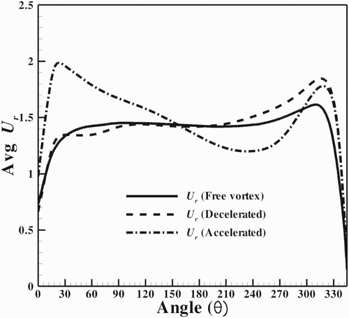
The distribution of the average radial velocity in different configurations along the circumference of the spiral casing exit is depicted in Figure . The average radial velocity in the accelerated type of spiral casing is not evenly distributed along the circumference. Except at the start and end cross-sections, the average radial velocity in the free-vortex and decelerated types of spiral casing is evenly distributed. Since the distributor part, which actually consists of stay vanes and guide vanes, has been modeled as porous media, the flow angles at various sections cannot be calculated at the distributor exit. Hence, the analysis of the exit flow along the circumference of the distributor outlet is limited. Flow with a uniform average radial velocity along the circumference of distributor exit is treated as better flow.
4.2. Effect of the aspect ratio on different configurations of spiral casing
In this section, the effect of the AR on the performance of three different configurations of spiral casing is studied. Here, AR<1 and AR>1 corresponds to an elliptical cross-sectional spiral casing with a major axis parallel to and perpendicular to a turbine axis, respectively. The AR is only varied along the cross-sections of the spiral part. The effect of the AR on the static pressure, radial velocity and tangential velocity distribution in sections HH, VV and GG at the turn cross-section in different configurations is shown in Figures –.
Figure 10. Distribution of (a) the static pressure, (b) the radial velocity and (c) the tangential velocity in section HH at the turn cross-section for various ARs in spiral casings of the type (i) decelerated, (ii) free vortex and (iii) accelerated.
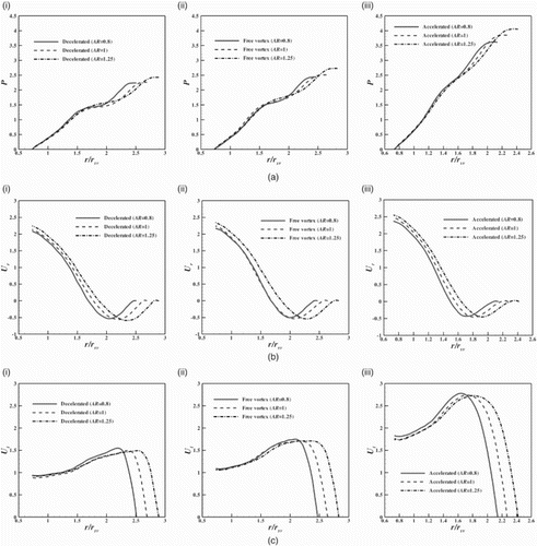
Figure 11. Distribution of (a) the static pressure, (b) the radial velocity and (c) the tangential velocity in section VV at the turn cross-section for various ARs in spiral casings of the type (i) decelerated, (ii) free vortex and (iii) accelerated.
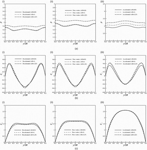
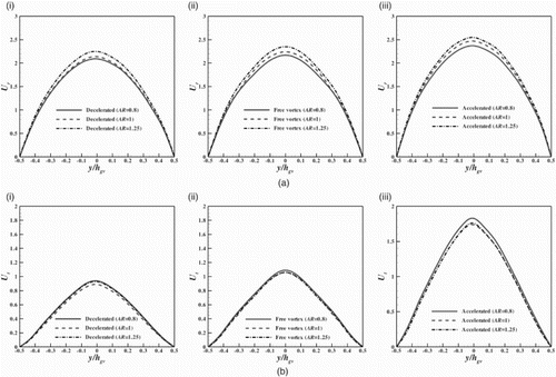
Figure 12. Distribution of (a) the radial velocity and (b) the tangential velocity in section GG at the turn cross-section for various ARs in spiral casings of the type (i) decelerated, (ii) free vortex and (iii) accelerated.
The static pressure distribution trend is similar in section HH in all the configurations of spiral casing (Figure (a)). In all configurations, the static pressure near the wall is high for AR>1 and low for AR<1. Moving from the decelerated (Figure (a)(i)) to the accelerated (Figure (a)(iii)) types of spiral casing, the static pressure near the wall increases owing to the corresponding tangential velocities. The radial velocity distribution patterns are similar in all configurations of different ARs (Figure (b)). In all configurations, the radial velocity at the distributor exit is greater for AR>1 and less for AR<1. The tangential velocity distribution patterns are also similar in section HH in the different configurations of spiral casing (Figure (c)). In the case of the decelerated type of spiral casing, the magnitude of the tangential velocity at the distributor exit is high for both elliptical cross-sectional spiral casings (AR<1 and AR>1) relative to the circular cross-sectional spiral casing (AR=1). In the case of the free-vortex and accelerated types of spiral casing, the magnitude of the tangential velocity at the distributor exit is higher for AR<1 than for the other ARs.
The static pressure distribution in section VV is almost uniform for all the ARs of the spiral casing cross-section and is found to be greater for AR>1 (Figure (a)). The variation of the radial velocity in section VV for different configurations with various ARs is shown in Figure (b). The radial velocity distribution pattern is the same for both the circular and elliptical cross-sectional spiral casings in all configurations. The inward as well as outward radial velocities increase with the aspect ratio. The tangential velocity distribution pattern is almost the same for the circular and elliptical cross-sectional decelerated and free-vortex types of spiral casing (Figure (c)(i) and (ii)). The magnitude of the tangential velocity decreases with increases in AR for the decelerated and free-vortex types of spiral casing. In the case of the accelerated type of spiral casing, there is no significant difference observed in the magnitudes of the tangential velocity in both the circular and elliptical cross-sectional spiral casings (Figure (c)(iii)).
The distribution pattern of the radial velocity in section GG is the same for both the circular and elliptical cross-sectional spiral casings in all configurations and is parabolic (Figure (a)). In all configurations, the radial velocity magnitude at the distributor exit is greater for AR>1 and less for AR<1 as compared to the circular cross-sectional spiral casing. The tangential velocity distribution pattern is also the same in all configurations of different ARs (Figure (b)). Its magnitude is high for both elliptical cross-sectional decelerated types of spiral casing (AR>1 and AR<1) as compared to the circular cross-sectional decelerated type (AR=1) (Figure (b)(i)). In the case of the free-vortex and accelerated types of spiral casing, the magnitude of the tangential velocity is high for the elliptical cross-sectional spiral casing of AR<1 as compared to the circular and elliptical cross-sectional spiral casings of AR>1 (Figure (b)(ii) and (iii)).
The effect of the AR on the average radial velocity at the distributor exit in the different configurations of spiral casing at different locations corresponding to values of the polar angle is shown in Figure . For all three configurations, the average radial velocity in section GG is greater for AR>1 and less for AR<1 as compared to the circular cross-sectional spiral casing. The variation of the average radial velocity follows the same trend, even though the AR increases (Figure ).
Figure 13. Distribution of the average radial velocity in section GG for different ARs in various cross-sections in spiral casings of the type (a) decelerated, (b) free vortex and (c) accelerated.

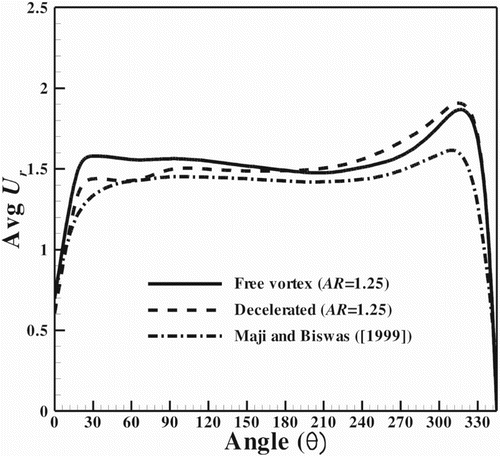
The distribution of average radial velocities in section GG for the free-vortex and decelerated types of spiral casing (AR=1.25) are shown in Figure . Both distributions are compared with the average radial velocity distribution of Maji and Biswas (Citation1999). It can be seen that both the decelerated and free-vortex types of spiral casing (AR=1.25) result in a high average radial velocity along the circumference of the spiral casing, but the free-vortex type (AR=1.25) attains a uniform and slightly higher (1.35) average radial velocity as compared to the decelerated type (AR=1.25).
Figure 14. Comparison of the average radial velocity in section GG for the free-vortex and decelerated types of spiral casing.
The total pressure loss for the different configurations of spiral casing with various ARs is shown in Table . The minimum total pressure loss indicates a maximum utilization of the total energy available in the casing. Irrespective of ARs, the total pressure loss is greater for the accelerated type of spiral casing and less for the decelerated type, as compared to the free-vortex type. In all configurations, the total pressure loss is found to be less for AR>1 and greater for AR<1, as compared to the circular cross-sectional spiral casing (AR=1). Of all the configurations of spiral casing with different ARs, the total pressure loss is found to be at the minimum and 11 less for the elliptical cross-sectional decelerated type of spiral casing with AR=1.25, as compared to the circular cross-sectional free-vortex type of spiral casing (Maji & Biswas, Citation1999). There is a reduction of about 7
in the total pressure loss for the decelerated type of spiral casing (AR=1.25) as compared to the free-vortex type (AR=1.25), even though the average radial velocity is uniform and slightly greater (1.35
) for the elliptical cross-sectional free-vortex type with AR=1.25.
Table 1. Total pressure loss in different configurations of spiral casing with different ARs.
The spiral velocity coefficient in different configurations of spiral casing with various ARs is shown in Table . Higher values of the spiral velocity coefficient indicate a proper reaction and the effective utilization of the available kinetic energy (Desai et al., Citation2010). Irrespective of the ARs, the spiral velocity coefficient is found to be greater for the decelerated type of spiral casing and less for the accelerated type, as compared to the free-vortex type. Except for the accelerated type, the spiral velocity coefficient is greater for AR>1 and less for AR<1, as compared to the circular cross-sectional spiral casing (AR=1). Of all the configurations of spiral casing with different ARs, the spiral velocity coefficient is highest for the decelerated type of spiral casing with AR>1 and its value is 12.11.
Table 2. Spiral velocity coefficients in different configurations of spiral casing with different ARs.
Inferences from the present study suggest that the elliptical cross-sectional decelerated type of spiral casing with AR>1 is the best configuration for minimum total pressure loss, maximum spiral velocity coefficient and uniform average radial velocity at the exit.
In general, the rotor component of the hydro turbine influences the flow field in the spiral casing due to the unsteady interaction between them. In the present study, the fluid flow through a spiral casing was simulated by solving steady RANS equations. In the case of the unsteady interaction between the rotor and the spiral casing, unsteady Reynolds average Navier-Stokes (URANS) equations must be solved. The results obtained in the present study can be used as the initial conditions when considering the unsteady interaction between the rotor and the spiral casing in future work.
5. Conclusions
Numerical analysis of the fluid flow dynamics in three-dimensional spiral casings was carried out using the SUPG finite-element method. Secondary flow exists in the cross-sections of spiral casings, its strength differing from one cross-section to another. A decrease in static pressure from the outer wall in the direction of the distributor exit was observed. The tangential velocity was found to be high for the accelerated type of spiral casing. The tangential velocity near the distributor exit increases for all configurations in the circumferential direction. The following conclusions are drawn:
An increase in radial velocity is observed at the distributor exit with an increase in AR.
The average radial velocity at the distributor exit is evenly distributed along the circumference for the free-vortex and decelerated types of spiral casing, but not for the accelerated type.
The average radial velocity at the distributor exit is greater for the elliptical cross-sectional spiral casing with AR>1.
The total pressure loss is less for the decelerated type of spiral casing and more for the accelerated type.
The total pressure loss is at minimum for any type of elliptical cross-sectional spiral casing with AR>1 as compared to the circular cross-sectional spiral casing.
Of all the configurations, the total pressure loss is at minimum for the elliptical cross-sectional decelerated type of spiral casing with AR>1.
The spiral velocity coefficient is greater for the elliptical cross-sectional decelerated type of spiral casing with AR>1.
The elliptical cross-sectional decelerated type of spiral casing with AR>1 is recommended as the optimum spiral casing.
Notation
| AR | = | aspect ratio ( |
| a | = | vertical axis |
| b | = | horizontal axis |
| D | = | inlet diameter of spiral casing |
| = | inlet velocity | |
| ν | = | kinematic viscosity |
| = | non-dimensional turbulent viscosity | |
| = | non-dimensionalized Darcy's coefficient | |
| = | non-dimensionalized coordinates in tensor form | |
| = | non-dimensionalized velocity components in tensor form | |
| τ | = | non-dimensionalized time |
| p | = | non-dimensionalized pressure |
| P | = | static pressure |
| = | radial velocity | |
| = | tangential velocity | |
| = | axial velocity | |
| R | = | radius of any cross-section |
| Re | = | Reynolds number |
| Avg | = | average |
Acknowledgments
The authors would like to thank Prof. Gautam Biswas, Director of IIT Guwahati, for providing the data needed from Maji and Biswas (Citation1999).
Disclosure statement
No potential conflict of interest was reported by the authors.
References
- Brooks A. N., & Hughes T. J. R. (1982). Streamline upwind/ Petrov-Galerkin formulations for convection dominated flows with particular emphasis on the incompressible Navier-Stokes equations. Computer Methods in Applied Mechanics and Engineering, 32, 199–259.
- Chorin A. J. (1967). A numerical method for solving incompressible viscous flow problems. Journal of Computational Physics, 2, 12–26.
- Ciocan G. D., Iliescu M. S., Vu T. C., Nennemann B., & Avellan F. (2007). Experimental study and numerical simulation of the FLINDT draft tube rotating vortex. Journal of Fluids Engineering, 129, 146–158.
- Dadfar R., Firoozabadi B., & Ahmadi G. (2010). Effect of different configurations on 3-D analysis of flow through stay vanes and guide vanes of a Francis turbine. Transaction B: Mechanical Engineering, 17, 419–432.
- Danish S. N., Khan S. U.-D., Umer U., Qureshi S. R., & Ma C. (2014). Performance evaluation of tandem bladed centrifugal compressor. Engineering Applications of Computational Fluid Mechanics, 8, 382–395.
- Desai J., Chauhan V., Roghelia A., & Soni V. (2010, December). Validation of hydraulic design of spiral casing and stay vanes of a Francis turbine using CFD. Paper presented at the 37th National and 4th International Conference on Fluid Mechanics and Fluid Power, Madras, India.
- Donea J., Giuliani S., Laval H., & Quartapelle L. (1982). Finite element solutions of the unsteady Navier-Stokes equations by a fractional step method. Computer Methods in Applied Mechanics and Engineering, 30, 53–73.
- Galindo J., Hoyas S., Fajardo P., & Navarro R. (2013). Set-up analysis and optimization of CFD simulations for radial turbines. Engineering Applications of Computational Fluid Mechanics, 7, 441–460.
- Gareev A., Kosasih B., & Cooper P. (2013). Analysis of interference factors of air turbine cascades. Engineering Applications of Computational Fluid Mechanics, 7, 496–506.
- Harlow F., & Welch J. (1982). Numerical calculation of time-dependent viscous incompressible flow of fluid with free surface. Physics of Fluids, 8, 2182–2188.
- Ingram G. (2009). Basic concepts in turbomachinery. Frederiksberg: Ventus.
- Kurokawa J., & Nagahara H. (1986, September). Flow characteristics in spiral casings of water turbines. Paper presented at the 13th International Association for Hydraulic Research Symposium on Hydraulic Machinery and Cavitation, Montreal, Canada.
- Lam P. A. K., & Prakash K. A. (2014). A numerical study on natural convection and entropy generation in a porous enclosure with heat sources. International Journal of Heat and Mass Transfer, 69, 390–407.
- Launder B. E., & Spalding D. B. (1974). The numerical computation of turbulent flows. Computer Methods in Applied Mechanics and Engineering, 3, 269–289.
- Liu H., Wang J., Wang Y., Huang H., & Jiang L. (2014). Partially-averaged Navier-Stokes model for predicting cavitating flow in centrifugal pump. Engineering Applications of Computational Fluid Mechanics, 8, 319–329.
- Li Z., & Zhang L. (2012). Research on numerical method of flow-induced vibration on spiral casing structure of large-scale hydropower station. Procedia Engineering, 31, 688–695.
- Maji P. K., & Biswas G. (1998). Three-dimensional analysis of flow in the spiral casing of a reaction turbine using a differently weighted Petrov Galerkin method. Computer Methods in Applied Mechanics and Engineering, 167, 167–190.
- Maji P. K., & Biswas G. (1999). Analysis of flow in the spiral casing using a streamline upwind Petrov Galerkin method. International Journal for Numerical Methods in Engineering, 45, 147–174.
- Maji P. K., & Biswas G. (2000). Analysis of flow in the plate-spiral of a reaction turbine using a streamline upwind Petrov-Galerkin method. International Journal for Numerical Methods in Fluids, 34, 113–144.
- Marjavaara B. D., & Lundstrom T. S. (2006). Redesign of a sharp heel draft tube by a validated CFD-optimization. International Journal for Numerical Methods in Fluids, 50, 911–924.
- Negru R., Muntean S., Marsavina L., Susan-Resiga R., & Pasca N. (2012). Computation of stress distribution in a Francis turbine runner induced by fluid flow. Computational Materials Science, 64, 253–259.
- Prakash K. A., Biswas G., & Kumar B. V. R. (2006). Thermal hydraulics of the spallation target module of an accelerator driven sub-critical system: A numerical study. International Journal of Heat and Mass Transfer, 49, 4633–4652.
- Prakash K. A., De S., Kumar B. V. R., & Biswas G. (2006). A SUPG–finite element study of an ADSS. Finite Elements in Analysis and Design, 42, 1123–1136.
- Price J. W. H. (1998). The failure of the Dartmouth turbine casing. International Journal of Pressure Vessels and Piping, 75, 559–566.
- Ravishankar S., & Prakash K. A. (2014). Numerical studies on thermal performance of novel cooling plate designs in polymer electrolyte membrane fuel cell stacks. Applied Thermal Engineering, 66, 239–251.
- Ravishankar S., & Prakash K. A. (2015). Enhanced cooling of electronic components using fluid flow under high adverse pressure gradient. Journal of Thermal Science and Engineering Applications, 7, 1–10.
- Saeed R. A., Galybin A. N., & Popov V. (2010). Modelling of flow-induced stresses in a Francis turbine runner. Advances in Engineering Software, 41, 1245–1255.
- Shyy W., & Vu T. C. (1991). On the adoption of velocity variable and grid system for fluid flow computation in curvilinear coordinates. Journal of Computational Physics, 92, 82–105.
- Susan-Resiga R. F., Muntean S., Avellan F., & Anton I. (2011). Mathematical modelling of swirling flow in hydraulic turbines for the full operating range. Applied Mathematical Modelling, 35, 4759–4773.
- Tridon S., Barre S., Ciocan G. D., & Tomas L. (2010). Experimental analysis of the swirling flow in a Francis turbine draft tube: Focus on radial velocity component determination. European Journal of Mechanics – B/Fluids, 29, 321–335.
- Trivedi C., Cervantes M. J., Gandhi B. K., & Dahlhaug O. G. (2013). Experimental and numerical studies for a high head Francis turbine at several operating points. Journal of Fluids Engineering, 135, 1–17.
- Wang F.-J., Li X.-Q., Ma J.-M., Yang M., & Zhu Y.-L. (2009). Experimental investigation of characteristic frequency in unsteady hydraulic behavior of a large hydraulic turbine. Journal of Hydrodynamics, Ser. B, 21, 12–19.
- Zhang L., Ren Y., Li Y., & Chen D. (2012). Hydraulic characteristic of cooling tower Francis turbine with different spiral casing and stay ring. Energy Procedia, 16, 651–655.
- Zhang L.-X., Wang W.-Q., & Guo Y. (2007). Intrinsic features of turbulent flow in strongly 3-D skew blade passage of a Francis turbine. Journal of Hydrodynamics, Ser. B, 19, 92–99.

