ABSTRACT
This paper presents a three-dimensional (3D) parallel multiple-relaxation-time lattice Boltzmann model (MRT-LBM) for Bingham plastics which overcomes numerical instabilities in the simulation of non-Newtonian fluids for the Bhatnagar–Gross–Krook (BGK) model. The MRT-LBM and several related mathematical models are briefly described. Papanastasiou’s modified model is incorporated for better numerical stability. The impact of the relaxation parameters of the model is studied in detail. The MRT-LBM is then validated through a benchmark problem: a 3D steady Poiseuille flow. The results from the numerical simulations are consistent with those derived analytically which indicates that the MRT-LBM effectively simulates Bingham fluids but with better stability. A parallel MRT-LBM framework is introduced, and the parallel efficiency is tested through a simple case. The MRT-LBM is shown to be appropriate for parallel implementation and to have high efficiency. Finally, a Bingham fluid flowing past a square-based prism with a fixed sphere is simulated. It is found the drag coefficient is a function of both Reynolds number (Re) and Bingham number (Bn). These results reveal the flow behavior of Bingham plastics.
1. Introduction
Bingham plastics or viscoplastic materials – such as cement mortar, slurries, and suspensions – are widely used in hydraulic and civil engineering. The most important characteristic of Bingham plastics is their yield stress, which defines the point above which flow occurs. Mathematical models for Bingham plastics include the Bingham model, the Herschel–Bulkley model, and the Casson model (Mitsoulis, Citation2007). The traditional methods of computational fluid dynamics (CFD), such as the finite-volume method (Neofytou, Citation2005; Xu, Yuan, Repke, & Wozny, Citation2012) and the finite-element method (Bell & Surana, Citation1994; Ozmen-Cagatay & Kocaman, Citation2011), are the most common numerical techniques used to simulate Bingham plastic flows. However, such traditional methods often produce inaccuracies in cases of complex geometries and boundary conditions (I.-B. Lee et al., Citation2013; Mendoza, Succi, & Herrmann, Citation2013; Riddle, Carruthers, Sharpe, McHugh, & Stocker, Citation2004). Despite the adoption of special techniques (Tezduyar, Citation2001; Tezduyar, Takizawa, Moorman, Wright, & Christopher, Citation2010) or complex grids (Deng, Mao, Tu, Zhang, & Zhang, Citation2012) to get round potential inaccuracies, simulations are cumbersome, thus prompting the development of a more efficient numerical method for Bingham plastics.
The lattice Boltzmann model (LBM) has been a successful substitute for traditional CFD methods in various liquid flows (Haghani, Rahimian, & Taghilou, Citation2013; C.-H. Lee, Huang, & Chiew, Citation2015). One of the most popular LBM models is the Bhatnagar–Gross–Krook (BGK) model, in which only one single-relaxation time is used (S. Chen & Doolen, Citation1998). Given its simplicity, the BGK is an efficient numerical method for non-Newtonian fluids. However, the BGK has a significant drawback concerning low-viscosity fluids where it is often the case that simulations are hampered by numerical instabilities. To overcome this disadvantage, Chai, Shi, Guo, and Rong (Citation2011) introduced the multiple-relaxation-time LBM (MRT-LBM) to model non-Newtonian fluids in 2D. The MRT-LBM achieved a much better performance in terms of numerical stability as different relaxation times can be individually adjusted in accordance with specific problems (Lallemand & Luo, Citation2000).
The LBM has several advantages, including a simple evolutional equation which is easy to parallelize with a high parallel efficiency (Aidun & Clausen, Citation2010). Wang, Zhang, Bengough, and Crawford (Citation2005) successfully simulated an incompressible flow in porous media through a cell-based domain-decomposition on different clusters. The parallel implementation and scaling results of a hybrid lattice Boltzmann (LB)/finite-element code for suspension flow simulations at the Argonne National Laboratory and IBM’s Blue Gene/P were presented and discussed by Clausen, Reasor, and Aidun (Citation2010). A flexible patch-based LB parallelization approach integrated into the waLBerla software framework was used to compare the parallel efficiencies of heterogeneous graphics processing unit (GPU) and central processing unit (CPU) clusters (Feichtinger et al., Citation2011). The LBM is effective in realistic simulations at different parallel efficiencies, which depend on the LBM codes and the architecture of the clusters used. However, in their work, only the BGK model was used in their test and comparison of parallel efficiency. In this study, therefore, we took the next logical step to verify and compare parallel performance using the MRT model.
This paper presents a three-dimensional (3D) parallel MRT-LBM for Bingham plastics as an extension of previous research. The 3D MRT-LBM and the Papanastasiou model (Papanastasiou, & Boudouvis, Citation1997) for Bingham fluids are introduced in section 2 and the impact of relaxation parameters on the MRT model for a Bingham fluid is discussed. Section 3 validates the 3D MRT-LBM for Bingham fluids and the results are presented. Section 4 discusses the parallel performance of the 3D MRT-LBM according to a benchmark cavity flow. Section 5 examines a Bingham fluid flowing past a square-based prism with a fixed sphere and conclusions are drawn in section 6.
2. Numerical method
2.1. D3Q19 MRT-LBM
D’Humieres (Citation1994) first proposed the MRT-LBM, also known as a generalized LBM. A few years later, a 3D MRT-LBM was developed (d’Humieres, Ginzburg, Krafczyk, Lallemand, & Luo, Citation2002), which demonstrated better numerical stability compared to a BGK-LBM for a Newtonian fluid. In this paper, a 3D MRT-LBM with a D3Q19 model is used. The evolution equation is:
(1)
where
,
is the density distribution function of a fluid particle at position
and time
with velocity
, and
is the equilibrium distribution function of
, which is given as
(2)
The weighting factors in the D3Q19 model are given as
(3)
The corresponding particle velocities are
(4)
The only difference between MRT and BGK is the collision matrix , where
is the transformation matrix. The role of
is to change
and
from the velocity space to the moment space with
and
, where
denotes the moment vector:
(5)
and the equilibrium value of
is given as follows:
(6a)
(6b)
(6c)
(6d)
(6e)
(6f)
(6g)
Details of ,
and
can be found in d’Humieres et al. (Citation2002).
is the diagonal relaxation matrix. The kinematic viscosity
is defined as (Lallemand & Luo, Citation2000):
(7)
The specific value of S can be found in section 2.4. The collision process and the propagation process are carried out in moment space and velocity space, respectively:
(8)
(9)
In Equations (8) and (9), denotes the post-collision density distribution function.
2.2. Papanastasiou model for Bingham fluids
Different constitutive equations have been proposed to model the stress-deformation behavior of viscoplastic materials (Bird, Dai, & Yarusso, Citation1983), among which the Bingham model is most popular due to its simplicity and can be shown as:
(10)
where
and
are the shear stress and yield stress, respectively,
is the shear rate, and
represents the plastic viscosity. Papanastasiou and Boudouvis (Citation1997) modified the equation as follows:
(11)
where
is introduced to overcome the discontinuity at
. In this paper, m is set to 108 (S.-G. Chen, Sun, Jin, & Liu, Citation2014). From Equation (11), the apparent viscosity can be obtained:
(12)
where
and
is the second invariant of the strain rate tensor
. Chai et al. (Citation2011) and Chai and Zhao (Citation2012) proved that
is a function of the density distribution function:
(13)
where
is the non- equilibrium part.
The relaxation factor can be obtained using Equation (7) once the apparent viscosity is known. The criterion used to track the flow (yielded) of Bingham fluids is when the magnitude of the extra stress
exceeds the yield stress
.
2.3. The effect of relaxation parameters in the MRT-LBM for Bingham fluid
For Newtonian fluid, it is understood that the MRT-LBM can overcome numerical instabilities at very low viscosities. However, the potential advantages of applying the MRT-LBM to Bingham fluid have not, so far, been studied. In this section, we examine the effect of relaxation parameters in MRT-LBM for the Bingham fluid using a numerical approach. For the sake of simplicity, we first consider a D2Q9 MRT-LBM. The results can easily be extended to 3D.
In the MRT-LBM, the density distribution functions, which have no physical meaning, can be decoupled through transformation. The new moment representations have an obvious physical significance, such as hydrodynamic quantities and their fluxes, etc. Thus, each relaxation parameter can be controlled independently using this mechanism.
In the D2Q9 MRT-LBM there are nine relaxation parameters: . We consider a classical benchmark – Poiseuille flow in dimensionless form. The boundary conditions are the same as those in S.-G. Chen et al. (Citation2014). The equivalent pressure gradient is
, the plastic viscosity
= 0.24, and the yield stress
= 0.004. The lattice spacing
, the time step
, and the density of the Bingham fluid
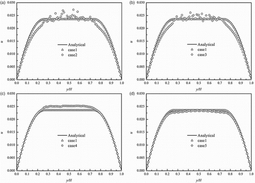
. Firstly, the following two cases were compared (Figure (a)). The relaxation parameters were the same as in our previous work for case 1, where S = (0, 1.1, 1.0, 0, 1.2, 0, 1.2,
,
), whereas all relaxation parameters were equal to
for case 2. It can be shown that the BGK-LBM cannot converge to an analytical solution, especially in the unyielded region where the shear rate is close to zero. On the contrary, the MRT-LBM solution agrees very well with the analytical solution, with an average error of only 0.25%.
Figure 1. Velocity profile of a central cross-section for the five cases. Case1: S = (0, 1.1, 1.0, 0, 1.2, 0, 1.2, 1/ω, 1/ω); case2: S = (1/ω, 1/ω, 1/ω, 1/ω, 1/ω, 1/ω, 1/ω, 1/ω, 1/ω); case3: S = (0, 1/ω, 1/ω, 0, 1/ω, 0, 1/ω, 1/ω, 1/ω); case4: S = (0, 1/ω, 1/ω, 0, 1.2, 0, 1.2, 1/ω, 1/ω); case5: S = (0, 1/ω, 1.0, 0, 1.2, 0, 1.2, 1/ω, 1/ω); (a) case1 and case2; (b) case1 and case3; (c) case1 and case4; (d) case1 and case5.
Considering that s0, s3 and s5 are related to the conserved quantities of density and linear momentum
, collisions in the moment space do not change these conserved quantities. Thus, in case 3 s0, s3 and s5 are set to 0, while other relaxation parameters are set to
. It can be seen from (b) that the deviations in the unyielded region are smaller than in case 2. Therefore, some higher-order moments have important effects for a Bingham fluid, which are often insignificant in a Newtonian fluid simulation.
The moments and
, which are third order according to Lallemand and Luo (Citation2000), relax with the relaxation parameters s4 and s6. In case 4, s4 and s6 are both equal to 1.2, while other relaxation parameters remain the same with case 3. A significant improvement in the unyielded region can be found in Figure (c). However, the maximum velocity is not in good agreement with the analytical solution.
The relaxation parameter s2, which is related to the fourth-order moment , is considered in case 5 and set to 1.0. It is obvious from Figure (d) that the result (the average error is 1.8%) is much better than in the other cases. The relaxation parameter s1 is determined by the bulk viscosity and s7 and s8 are determined by shear viscosity. If s1 is equal to 1.1 and s7 and s8 are set to
, the standard MRT-LBM is recovered and a more accurate solution is obtained.
From the numerical analysis of the relaxation parameters it was found that the higher-order moments have a significant effect on the numerical stability in the unyielded region where the shear rate is close to 0. By adjusting the relaxation parameters carefully, the MRT-LBM can overcome this numerical instability in the unyielded region. We conclude, therefore, that the MRT-LBM is more suitable than the BGK-LBM for the simulation of Bingham fluids.
Through the same method as above, the relaxation parameters in 3D can also be determined when the error between numerical and analytical solutions is small enough. In this paper,
, and
.
2.4. Dimensionless numbers
In this work, the Reynolds number Re and the Bingham number Bn are used to present the simulation results for standard comparisons:
(14)
where
is the density of the Bingham fluid,
is the characteristic length, and
is the characteristic velocity.
For spherical particles the drag coefficient Cd, which is a dimensionless parameter, is usually employed:
(15)
where
is the drag force in the flow direction and
is the radius of the spherical solid particle.
Previous studies (Beris, Tsamopoulos, Armstrong, & Brown, Citation1985; Blackery & Mitsoulis, Citation1997; Yoshino, Hotta, Hirozane, & Endo, Citation2007) have used Stokes’ drag coefficient Cs to measure the relationship between this dimensionless parameter and the yield stress. The current study also uses Cs, which is expressed as
(16)
3. Validation of the 3D MRT-LBM
3.1. 3D Poiseuille flow through the cross-section of a circular tube
A 3D steady Poiseuille flow through a circular tube was used to validate the 3D MRT-LBM. All the conditions for this simulation are in dimensionless form. The simulation domain has uniform lattices (
). The pressure boundary conditions put forward by Zou and He (Citation1997) are used at the inlet and outlet. The pressure gradient
in lattice units. The halfway bounce-back boundary condition is applied to other walls. The lattices outside the tube remain unchanged to save on computational time. The plastic viscosity
is set to 0.2, and Re is fixed at 0.95. The Bn varies from 0 to 80 as the yield stress
increases from 0 to 0.00010. The lattice spacing
, the time step
and the density of the Bingham fluid
. The analytical solution is given by Chatzimina, Georgiou, Argyropaidas, Mitsoulis, and Huilgol (Citation2005):
(17)
where
is the yield point given by
, and
.
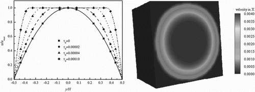
Figure shows the analytical solutions (solid lines) and numerical results (dots). The velocity profile is a parabola at first, when yield stress is small. As the yield stress increases the profile changes to a flat plateau (i.e., an unyielded region). The numerical results match the analytical solutions well, which proves that the 3D MRT-LBM is an effective tool for the simulation of Bingham fluids.
Figure 2. Velocity profile of a cross-section of the circular tube, showing (left) the numerical simulation and corresponding analytical solution at different yield stresses (x = 24, z = 30) and (right) the velocity profile of the central cross-section.
The accuracy of the MRT-LBM approach has been studied by Chai et al. (Citation2011) and it is second-order accurate in space, which is affected by fluid compressibility. Thus, the maximum Ma () in their simulation is 0.016 when
is 0, which is much smaller than 1.0 in order to ensure a reasonably accurate solution.
3.2. 3D Poiseuille flow through the cross-section of a square tube
The 3D MRT-LBM approach was further employed to simulate the Poiseuille flow through a square tube. The simulation domain has uniform lattices; all other computational conditions are the same as those in section 3.1, including the pressure gradient and boundary conditions.
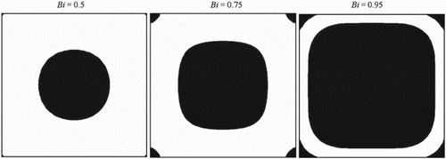
As is shown by Figure , our results are consistent with those of Vikhansky (Citation2008). The unyielded zones include two types: dead zones at the corners and a plug zone at the center. A single parameter Bi, which is similar to the Bingham number Bn, governs the distribution of the yielded and unyielded zones. The rates of the radius of the unyielded region to the side length at different values of Bi are 0.51, 0.74, and 0.95.
4. The parallel performance of the MRT-LBM
Equations (1), (8), and (9) indicate that the calculation of the LBM is local and that only information regarding the nearest neighbor cells is used during each time step (Kandhai et al., Citation1998). This spatial locality makes the LBM very well suited to parallel computing.
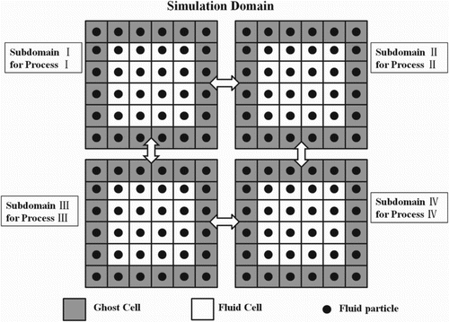
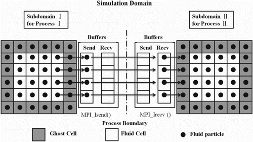
An equal-subdomain partitioning technique was used to divide the domain into subdomains and the message-passing interface (MPI) library (Figures and ) was adopted to transfer data between subdomains (Feichtinger et al., Citation2011; Wang et al., Citation2005). A Bingham fluid flowing in a cubic cavity was used as a benchmark to verify the parallel performance of the 3D MRT-LBM. Numerical experiments were conducted on the High-Performance Computing Architecture of the Tsinghua National Laboratory for Information Science and Technology, China. The details of this architecture are as follows:
Peak performance of 104 Teraflops with 740 computing nodes (37 racks of 20 nodes).
Each node contains two Intel Xeon X5670 (2.93 GHz, 12 MB cache) CPUs, each with six cores (a total of 8880 processor cores; 1 rack = 240 cores).
32 or 48 GB RAM per node (28.9 TB in total).
Bandwidth of up to 5.1 GB/s.
Figure 5. Design for parallel simulations.
Generally, the turnaround of one iteration is the sum of the times for calculation
and communication
. Thus,
(18)
(19)
where a and b are parameters related to the architecture, U is the computation speed, V is the communication speed, N is the lattice resolution, and n is the number of processors (Wang et al., Citation2005).
Weak scaling and strong scaling (Kandhai et al., Citation1998) are two of the most common methods for the evaluation of scaling performance. Concerning weak scaling, the subdomain size for one processor remains fixed while the domain size is enlarged. As for strong scaling, the processing core number is increased, whereas the domain size is fixed. Two parameters, the speedup factor S and efficiency E, are calculated to assess the parallel computation:
(20)
where
and
are the running times when a single processor and n processors are used, respectively.
Equation (19) indicates that in weak scaling, is constant; thus,
remains fixed whereas
increases as the lattice resolution N increases and
is a linear function of
. By contrast, in strong scaling,
and
remain unchanged whereas
decreases with an increasing processor number; thus,
is proportional to
.
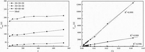
The weak scaling results are shown in Figure . The larger the subdomain size, the longer the time required to run 4000 iterations. The total run time , and particularly the communication time
, increase slowly with an increasing number of cores;
and
also hold a linear relationship (Equation (19)).
Figure 6. Weak scaling results for the 3D MRT-LBM showing (left) total run time for 4000 iterations at different fixed subdomain sizes and (right) the linear relationship between and
according to Equation (19).
The strong scaling results are shown in Figure . For one domain size, the total computing time keeps a perfect linear relationship with the inverse of n, consistent with the theoretical result from Equation (19). The speedup first increases and then saturates as more processors are used for a fixed domain size. When the same number of processors is used, a higher speedup and efficiency can be obtained with a larger computational domain. Both speedup and efficiency decrease as the number of processors increases because more time is spent on communications. Besides, the efficiency E with different processor numbers also relates to the domain size: a larger domain size implies a higher efficiency. Sometimes, the speedup can be larger than the number of processors, and the efficiency is higher than that which results from the optimized use of cache memory.
Figure 7. Strong scaling results for the 3D MRT-LBM showing (a) total run time for 4000 iterations at different domain sizes, (b) the linear relationship between and
according to Equation (19), (c) speedup, and (d) efficiency.
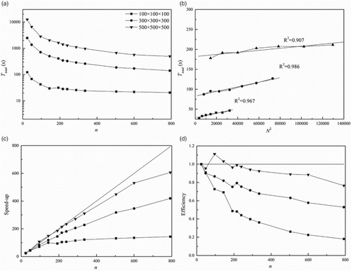
In conclusion, the proposed 3D MRT-LBM is appropriate for parallel implementation, especially for large domain sizes. The parallel efficiency is around 80% when the domain size is 500×500×500 and 792 processors are used. From Equation (8), the evolution equation of the MRT model is more complex than that of the BGK model, and a matrix needs to be solved during each step. Thus the computational cost of the MRT model is larger; however, the time spent on communication is almost the same in both models. As a result, the parallel speedup or efficiency of the MRT is better than that of the BGK since the percentage of communication time is smaller. The parallel performance of the BGK and MRT models are also dependent on the domain size and the number of processors used. Generally, with a larger domain size and more processors, a better parallel efficiency can be achieved with the MRT model. For example, with a domain size of 500×500×500, the total computational time of the MRT is twice that of the BGK when 24 cores are used, but this decreases to 1.2 times when 792 cores are used. When 24 cores and 792 cores are used, the speedup increases from 24 to 475 and the efficiency decreases from 1.00 to 0.60 for the BGK model, contrasting with a speedup increase from 24 to 607 and a decrease in efficiency from 1.00 to 0.78 for the MRT model. Therefore, the parallel performance of the MRT model is better than that of the BGK model, although the total computational time of the MRT is greater. Concerning parallel efficiency, it is certain that the total computational time of the MRT model can be further decreased through the use of more processors.
5. Bingham fluid flows around a fixed sphere
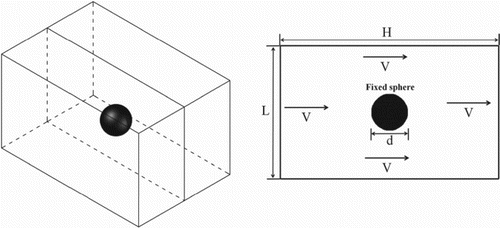
A Bingham fluid flowing around a sphere is an important benchmark problem in fluid mechanics. Because no analytical solution yet exists, many researchers (Beris et al., Citation1985; Blackery & Mitsoulis, Citation1997; Prashant & Derksen, Citation2011) have tried to solve this problem using different numerical methods, such as the finite element method and the LBM. In this paper, a solution for the problem is investigated based on the proposed MRT-LBM. The calculated domain is a square-based prism with a size of 4×4×6 (L/d×L/d×H/d). The spatial resolution is such that the spherical radius spans 6 lattices. The sphere is assumed to be stationary, and the walls of the prism and the fluid move at a constant velocity V (Figure ). Such a resolution is sufficient for achieving a reasonable accuracy (Derksen, Citation2008; Derksen & Sundaresan, Citation2007). The circular boundary is approximated by a series of stairs, and the moment exchange method is applied to calculate the force imposed on the sphere.
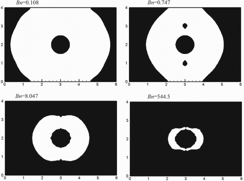
To ensure a creeping flow, Re is set to 0.001, while Bn is varied from 0.108 to 544.5 to draw comparisons with the results of Blackery and Mitsoulis (Citation1997). In all cases, Cs is calculated; the yielded and unyielded regions are shown in Figure . These qualitative results are consistent with those reported by Blackery and Mitsoulis (Citation1997).
Figure 9. Yielded (white) and unyielded (black) regions for Bingham fluid flowing around a fixed sphere for different values of Bn.
Aside from the qualitative results, a quantitative term Cs is compared with that of Blackery and Mitsoulis (Citation1997), who determined an approximate relationship between Cs and Bn:
(21)
As shown in Figure and Table , the numerical results using the MRT-LBM (square dots) are in good agreement with those derived from Equation (21) (solid lines). The average deviation between the present result and the reference data is only 1.22%. As yield stress increases, the resistance effect of the fixed sphere becomes larger. As a result, Cs increases as Bn increases.
Figure 10. Cs increases as Bn increases, as observed by Blackery and Mitsoulis (Citation1997).
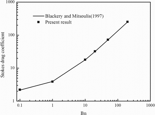
Table 1. The deviations between the present result and the reference data.
As with the 2D case (S.-G. Chen et al., Citation2014), the drag coefficient Cd is composed of two parts:
(22)
In Equation (22), CdB and CdN are the drag coefficients from Bingham fluid and Newtonian fluid, respectively.
A relation for CdN is provided according to the work of Owen, Leonardi, and Feng (Citation2011):
(23)
Concerning a spherical particle in a Bingham plastic, for settlement to occur the diameter of the spherical particle has to be larger than a critical diameter . Bethmont et al. (Citation2003) have shown that a general form of this criterion can be written as
(24)
where
is the yield stress,
is the density of the particle,
is the density of the fluid, and K is a constant. However, the existing data suggest significantly dispersed values for K (between 11 and 25; see Roussel, Citation2006). For example, Beris et al. (Citation1985) determined that K = 20.97 while Ansley and Smith’s (Citation1967) determined that K = 16.5. In this paper, the value of K is presented according to the results of the MRT-LBM.
According to Equation (24), the drag force on a spherical particle to overcome the yield stress can be expressed as follows:
(25)
Introducing Equations (25) and (14) into Equation (15), CdB can be derived theoretically:
(26)
Combining Equation (26) with Equation (23), the drag coefficient can be expressed as follows:
(27)
The drag coefficients for different values of Bn and Re are listed in Table . With the data in Table , a value of K = 21.61 was determined using the least squares method with an associated minimum error of 7.4%. This result is similar to that of Beris et al. (Citation1985), which was obtained using the finite-element method. Thus,
(28)
Table 2. The drag coefficients for different values of Bn and Re.
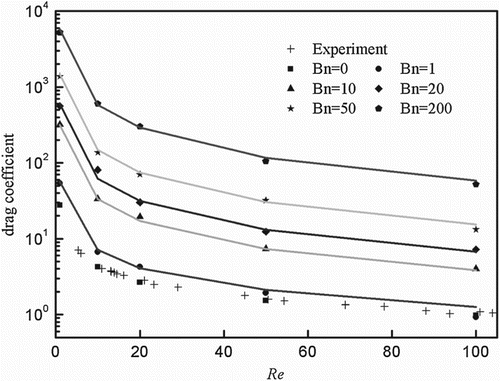
Figure compares the numerical results (unfilled dots) with Equation (28) (colored lines), which further proves that Equation (28) can be applied to predict the drag coefficient of the sphere particle in Bingham flows. The present results indicate that increasing Bn substantially increases the drag coefficient in the system when Re is constant, while increasing Re decreases the drag coefficient for the same values of Bn; Newtonian fluids are also characterized by this phenomenon.
6. Conclusions
A 3D MRT-LBM has been proposed for Bingham fluids in this paper. Numerical evidence supporting the assertion that the MRT-LBM is better than the BGK-LBM in terms of stability and accuracy has been presented. The MRT-LBM was validated using the Poiseuille flow, which served as a benchmark. The flat plateau of the velocity profile widens as the yield stress increases. The consistency between the numerical and analytical solutions validates the 3D MRT-LBM. The parallel computing experiments show that the proposed model is appropriate for parallel implementation, with a high level of parallel efficiency.
The application of the MRT-LBM to a two-phase system, which comprised the interaction between a Bingham fluid and a fixed sphere, indicated that the highly viscous region (unyielded region) becomes larger as Bn increases. The qualitative relationship between CS and Bn also confirms the effectiveness of the 3D MRT-LBM. Finally, concerning the drag coefficient on a fixed sphere, it was found that, in contrast to the Newtonian fluid, the drag coefficient is impacted by both Re and Bn.
This work demonstrated some characteristic flow behavior of Bingham plastics but used only a relatively simple scenario for the verification of the 3D parallel MRT-LBM because the current main focus was on the development of the numerical tool.
Simulating realistic flow problems such as self-compacted concrete flowing through porous material is our ultimate aim because such flows are of principal significance in hydraulic engineering. Therefore, our future work will focus on the 3D fluid–particle interaction for Bingham fluids.
Acknowledgments
We thank the anonymous referees for their comments and suggestions. The technical support received from the Tsinghua National Laboratory for Information Science and Technology is gratefully acknowledged.
Disclosure statement
No potential conflict of interest was reported by the authors.
Additional information
Funding
References
- Aidun, C. K., & Clausen, J. R. (2010). Lattice-Boltzmann method for complex flows. Annual Review of Fluid Mechanics, 42(1), 439–472. 10.1146/annurev-fluid-121108-145519
- Ansley, R. W., & Smith, T. N. (1967). Motion of spherical particles in a Bingham plastic. AIChE Journal, 13(6), 1193–1196.
- Bell, B. C., & Surana, K. S. (1994). p-version least squares finite element formulation for two-dimensional, incompressible, non-Newtonian isothermal and non-isothermal fluid flow. International Journal for Numerical Methods in Fluids, 18(2), 127–162.
- Beris, A. N., Tsamopoulos, J. A., Armstrong, R. C., & Brown, R. A. (1985). Creeping motion of a sphere through a Bingham plastic. Journal of Fluid Mechanics, 158(Sep), 219–244. doi:10.1017/S0022112085002622
- Bethmont, S., Schwarzentruber, L., Stefani, C., Leroy, R., Wallevik, O., & Nielsson, I. (2003). Defining the stability criterion of a sphere suspended in a cement paste: A way to study the segregation risk in self compacting concrete (SCC). Paper presented at the 3rd International Symposium on Self-Compacting Concrete.
- Bird, R. B., Dai, G., & Yarusso, B. J. (1983). The rheology and flow of viscoplastic materials. Rev. Chem. Eng, 1(1), 1–70.
- Blackery, J., & Mitsoulis, E. (1997). Creeping motion of a sphere in tubes filled with a Bingham plastic material. Journal of Non-Newtonian Fluid Mechanics, 70(1–2), 59–77. doi:10.1016/S0377-0257(96)01536-4
- Chai, Z., Shi, B., Guo, Z., & Rong, F. (2011). Multiple-relaxation-time lattice Boltzmann model for generalized Newtonian fluid flows. Journal of Non-Newtonian Fluid Mechanics, 166(5–6), 332–342. 10.1016/j.jnnfm.2011.01.002
- Chai, Z., & Zhao, T. S. (2012). Effect of the forcing term in the multiple-relaxation-time lattice Boltzmann equation on the shear stress or the strain rate tensor. Physical Review E, 86(1). doi:10.1103/Physreve.86.016705
- Chatzimina, M., Georgiou, G. C., Argyropaidas, I., Mitsoulis, E., & Huilgol, R. R. (2005). Cessation of Couette and Poiseuille flows of a Bingham plastic and finite stopping times. Journal of Non-Newtonian Fluid Mechanics, 129(3), 117–127. doi:10.1016/j.jnnfm.2005.07.001
- Chen, S., & Doolen, G. D. (1998). Lattice Boltzmann method for fluid flows. Annual Review of Fluid Mechanics, 30, 329–364. doi:10.1146/annurev.fluid.30.1.329
- Chen, S.-G., Sun, Q.-C., Jin, F., & Liu, J.-G. (2014). Simulations of Bingham plastic flows with the multiple-relaxation-time lattice Boltzmann model. Science China Physics, Mechanics and Astronomy, 57(3), 532–540. 10.1007/s11433-013-5178-2
- Clausen, J. R., Reasor, D. A., & Aidun, C. K. (2010). Parallel performance of a lattice-Boltzmann/finite element cellular blood flow solver on the IBM Blue Gene/P architecture. Computer Physics Communications, 181(6), 1013–1020. doi:10.1016/j.cpc.2010.02.005
- Deng, X. G., Mao, M. L., Tu, G. H., Zhang, H. X., & Zhang, Y. F. (2012). High-order and high accurate CFD methods and their applications for complex grid problems. Communications in Computational Physics, 11(4), 1081–1102. doi:10.4208/cicp.100510.150511s
- Derksen, J. J. (2008). Flow-induced forces in sphere doublets. Journal of Fluid Mechanics, 608, 337–356. 10.1017/S0022112008002309
- Derksen, J. J., & Sundaresan, S. (2007). Direct numerical simulations of dense suspensions: Wave instabilities in liquid-fluidized beds. Journal of Fluid Mechanics, 587, 303–336. doi:10.1017/S0022112007007094
- d’Humieres, D. (1994). Generalized lattice-Boltzmann equations. Rarefied gas dynamics-Theory and simulations, 450–458.
- d’Humieres, D., Ginzburg, I., Krafczyk, M., Lallemand, P., & Luo, L. S. (2002). Multiple-relaxation-time lattice Boltzmann models in three dimensions. Philosophical Transactions of the Royal Society A: Mathematical, Physical and Engineering Sciences, 360(1792), 437–451. doi:10.1098/rsta.2001.0955
- Feichtinger, C., Habich, J., Köstler, H., Hager, G., Rüde, U., & Wellein, G. (2011). A flexible Patch-based lattice Boltzmann parallelization approach for heterogeneous GPU–CPU clusters. Parallel Computing, 37(9), 536–549. doi:10.1016/j.parco.2011.03.005
- Haghani, R., Rahimian, M. H., & Taghilou, M. (2013). Lbm simulation of a droplet dripping down a hole. Engineering Applications of Computational Fluid Mechanics, 7(4), 461–470.
- Kandhai, D., Koponen, A., Hoekstra, A. G., Kataja, M., Timonen, J., & Sloot, P. M. A. (1998). Lattice-Boltzmann hydrodynamics on parallel systems. Computer Physics Communications, 111(1–3), 14–26. 10.1016/S0010-4655(98)00025-3
- Lallemand, P., & Luo, L.-S. (2000). Theory of the lattice Boltzmann method: Dispersion, dissipation, isotropy, Galilean invariance, and stability. Physical Review E, 61(6), 6546–6562.
- Lee, C.-H., Huang, Z- H., & Chiew, Y.-M. (2015). An extrapolation-based boundary treatment for using the lattice Boltzmann method to simulate fluid-particle interaction near a wall. Engineering Applications of Computational Fluid Mechanics, 9(1), 370–381. 10.1080/19942060.2015.1061554
- Lee, I.-B., Bitog, J. P. P., Hong, S.-W., Seo, I.-H., Kwon, K.-S., Bartzanas, T., & Kacira, M. (2013). The past, present and future of CFD for agro-environmental applications. Computers and Electronics in Agriculture, 93, 168–183. doi:10.1016/j.compag.2012.09.006
- Mendoza, M., Succi, S., & Herrmann, H. J. (2013). Flow through randomly curved manifolds. Scientific Reports, 3. doi:Artn310610.1038/Srep03106
- Mitsoulis, E. (2007). Flows of viscoplastic materials: Models and computations. Rheology Reviews, 135–178.
- Neofytou, P. (2005). A 3rd order upwind finite volume method for generalised Newtonian fluid flows. Advances in Engineering Software, 36(10), 664–680. 10.1016/j.advengsoft.2005.03.011
- Owen, D. R. J., Leonardi, C. R., & Feng, Y. T. (2011). An efficient framework for fluid-structure interaction using the lattice Boltzmann method and immersed moving boundaries. International Journal for Numerical Methods in Engineering, 87(1–5), 66–95. doi:10.1002/nme.2985
- Ozmen-Cagatay, H., & Kocaman, S. (2011). Dam-break flow in the presence of obstacle: experiment and CFD simulation. Engineering Applications of Computational Fluid Mechanics, 5(4), 541–552.
- Papanastasiou, T. C., & Boudouvis, A. G. (1997). Flows of viscoplastic materials: Models and computations. Computers & Structures, 64(1–4), 677–694. 10.1016/S0045-7949(96)00167-8
- Prashant, A. G, & Derksen, J. J. (2011). Direct simulations of spherical particle motion in Bingham liquids. Computers & Chemical Engineering, 35(7), 1200–1214. 10.1016/j.compchemeng.2010.09.002
- Riddle, A., Carruthers, D., Sharpe, A., McHugh, C., & Stocker, J. (2004). Comparisons between FLUENT and ADMS for atmospheric dispersion modelling. Atmospheric Environment, 38(7), 1029–1038. doi:10.1016/j.atmosenv.2003.10.052
- Roussel, N. (2006). A theoretical frame to study stability of fresh concrete. Materials and Structures, 39(1), 81–91. doi:10.1617/s11527-005-9036-1
- Tezduyar, T. E. (2001). Finite element methods for flow problems with moving boundaries and interfaces. Archives of Computational Methods in Engineering, 8(2), 83–130. doi:10.1007/Bf02897870
- Tezduyar, T. E., Takizawa, K., Moorman, C., Wright, S., & Christopher, J. (2010). Space-time finite element computation of complex fluid-structure interactions. International Journal for Numerical Methods in Fluids, 64(10–12), 1201–1218. doi:10.1002/fld.2221
- Vikhansky, A. (2008). Lattice-Boltzmann method for yield-stress liquids. Journal of Non-Newtonian Fluid Mechanics, 155(3), 95–100. doi:10.1016/j.jnnfm.2007.09.001
- Wang, J., Zhang, X., Bengough, A. G., & Crawford, J. W. (2005). Domain-decomposition method for parallel lattice Boltzmann simulation of incompressible flow in porous media. Physical Review E, 72(1), 16706. 10.1103/PhysRevE.72.016706
- Xu, Y. Y., Yuan, J. Q., Repke, J. U., & Wozny, G. (2012). Cfd study on liquid Flow behavior on inclined flat plate focusing on effect of flow rate. Engineering Applications of Computational Fluid Mechanics, 6(2), 186–194.
- Yoshino, M., Hotta, Y., Hirozane, T., & Endo, M. (2007). A numerical method for incompressible non-Newtonian fluid flows based on the lattice Boltzmann method. Journal of Non-Newtonian Fluid Mechanics, 147(1–2), 69–78. 10.1016/j.jnnfm.2007.07.007
- Zou, Q. S., & He, X. Y. (1997). On pressure and velocity boundary conditions for the lattice Boltzmann BGK model. Physics of Fluids, 9(6), 1591–1598. doi:10.1063/1.869307

