
ABSTRACT
The micro viscous pump is an important type of fluidic device. Optimizing the working performance of the pump is crucial for its wider application. A micro viscous pump design with unequal inlet and outlet areas is proposed in this paper. The flow field of the viscous pump is investigated using 2D laminar simulations. The mass flow rate and driving power are studied with different opening angles. The effects of the Reynolds number and the pressure load on the working performance are discussed in detail. Flow structures and vortex evolution are analyzed. With larger inlet and outlet areas, a higher mass flow rate is obtained and less driving power is achieved. A high pressure load results in a reduction in mass flow rate and an increase in driving power. Pumps with large opening angles are more susceptive to the Reynolds number and the pressure load. The adverse impact of the pressure load can be reduced by increasing the rotor speed. The vortex structure is affected by the geometric and operating parameters in the flow field. The flow dynamical behavior of the viscous pump exerts significant influence on its pumping ability. The present work gives rise to performance improvements for the micro viscous pump.
Nomenclature
| D | = | Diameter of the rotor (m) |
| din | = | Diameter of the inlet pipe (m) |
| dout | = | Diameter of the outlet pipe (m) |
| e | = | Deflected distance of the rotor (m) |
| H | = | Width of the passage in a standard pump (m) |
| Lu | = | Length of the upstream channel (m) |
| Ld | = | Length of the downstream channel (m) |
| m | = | Mass flow rate of the pump (kg s−1) |
| minlet | = | Mass flow rate at the inlet (kg s−1) |
| moutlet | = | Mass flow rate at the outlet (kg s−1) |
| M | = | Dimensionless mass flow |
| P | = | Pressure (Pa) |
| = | Dimensionless pressure load | |
| Pu | = | Pressure at the inlet (Pa) |
| Pd | = | Pressure at the outlet (Pa) |
| Re | = | Reynolds number |
| T | = | Dimensionless driving power |
| u | = | Velocity (m s−1) |
| ux | = | Horizontal velocity component (m s−1) |
| uy | = | Vertical velocity component (m s−1) |
| U | = | Characteristic velocity (m s−1) |
| x | = | Horizontal coordinate (m) |
| y | = | Vertical coordinate (m) |
Greek Symbols
| Greek Symbols | ||
| = | Kinematic viscosity (m2 s−1) | |
| ω | = | Angular speed of the rotor (rad/s) |
| ρ | = | Density of the fluid (kg m−3) |
| τ | = | Wall shear stress (Pa) |
| θ | = | Opening angle of the inlet (°) |
| ϕ | = | Opening angle of the outlet (°) |
| = | Tolerance value |
1. Introduction
Micro pumps are essential for fluid transport in microfluidic devices. They are appropriate for medical applications in tiny drug- or blood-delivery systems to transport precisely-metered doses (Geipel et al., Citation2007). Because of their simple structure, they can be used to control the flow of biological fluids for chemical and biological analysis tools (C. Zhang, Da, & Li, Citation2007). In compact electronic systems such as fuel cells, novel micro pumping solutions are important for a wider use of liquid cooling (T. Zhang & Wang, Citation2005). Micro pumps are also used in separation devices and micro sensors (Blanchard & Ligrani, Citation2006). Investigations of the pumping mechanism and working performance of micro pumps are crucial for their diverse application (Laser & Santiago, Citation2004).
Micro pumps have been proposed based on various pumping mechanisms, including interfacial phenomena (Yun, Cho, Bu, Kim, & Yoon, Citation2002), phase change (Yin & Prosperetti, Citation2005), and electrochemical process (Pramod & Sen, Citation2014). Several kinds of pumps are actuated by thermo-pneumatic function (Kim, Na, Kang, & Kim, Citation2005) and magnetic force (Jian, Si, Chang, & Liu, Citation2015). Iverson and Garimella (Citation2008) present a detailed review of the advances in the pumping technology of micro pumps. They state that among types of micro pump, the viscous pump has become a hot topic in the research literature for its simplicity in design and fabrication. In the viscous pump, viscous forces dominate over centrifugal forces and inertia forces as a result of the micro dimension (Blanchard, Ligrani, & Gale, Citation2006). The viscous forces introduced by two relatively moving surfaces are employed to induce fluid motion and achieve a pumping effect. Pulseless flow rate and steady pressure rise can be generated. No dynamic seals or valves are needed (Mainland & Green, Citation1992).
Viscous pumps mainly consist of disk pumps, spiral-channel pumps and cylinder pumps. In the disk viscous pump, fluid is pumped out after an exchange of momentum with the rotating disk. Single-disk and double-disk viscous pumps have been fabricated by Blanchard et al. (Citation2005). A multi-plate pump was also studied by Wang, Okamoto, Yamaguchi, and Teramoto (Citation2014). For spiral-channel viscous pumps, the channel has a spiral shape and a rotating upper boundary is used to drive the flow around the spiral. Spiral curvature and stream function solutions for analyzing the spiral-channel pump have been reported by Kilani and Al-Salaymeh (Citation2007) and Haik, Kilani, Hendrix, Rifai, and Galambos (Citation2007). Compared to disk and spiral-channel viscous pumps, the structure of the cylinder pump is much simpler. This type was first introduced by Sen, Wajerski, and Gad-el-Hak (Citation1996). A single rotating cylinder is placed eccentrically inside a channel between two parallel plates. Due to the unequal shear rate on the upper and lower surfaces of the rotating cylinder induced by the asymmetrical configuration, a net flow rate can be acquired.
The cylinder viscous pump has attracted extensive interest since its proposal. Computational fluid dynamics (CFD) simulations have been widely used in its study. Numerical simulation of the cylinder viscous pump was conducted by Sharatchandra, Sen, and Gad-el-Hak (Citation1997), who explored the parametric effects of geometrical structure on pumping ability. Later, the same team conducted another numerical simulation by considering the thermal effect on pump performance (Sharatchandra, Sen, & Gad-el-Hak, Citation1998). Abdelgawad, Hassan, and Esmail (Citation2004) comprehensively discussed the effects of operating conditions on the transient fluid performance around the rotor. Phutthavong and Hassan (Citation2004) numerically investigated the flow behaviors introduced by the rotating cylinder with different rotor geometries. It was suggested that the non-circular rotor shape could induce distinct flow structures and pump performance. Yokota, Sato, and Itoh (Citation2006) elaborately clarified the pump mechanism for a cylinder viscous pump, where various vortex structures were detected. Recently, Leontidis, Chen, Baldas, and Colin (Citation2014) studied the slip flow condition using CFD calculations. Related to the fundamental mechanism of the flow field in the cylinder viscous pump, the dynamics of flow over a rotating cylinder have been explored (Martín-Alcántara, Sanmiguel-Rojas, & Fernandez-Feria, Citation2015; Rao, Thompson, Leweke, & Hourigan, Citation2015).
To acquire a better pumping ability and higher efficiency, refined configurations of the cylinder viscous pump have been studied. Lu and Ding (Citation2010) investigated the flow patterns and dynamical performance of a viscous pump with aligned and staggered rotors in a straight channel. They also studied a novel viscous pump with a groove under the rotor using the commercial CFD software Fluent (Lu, Jing, Yang, & Yang, Citation2014). Choi, Lee, Choi, and Maeng (Citation2010) optimized the pump structure with two rotating cylinders with the aim of attaining maximum efficiency. Silva, Kobayashi, and Coimbra (Citation2007) proposed two curved housed pumps with L- and U-shaped housings. It was suggested that through comparisons with pumps with straight housing, curved housed pumps would be shown to generate a higher mass flow rate while demanding less shaft power to operate. Kang (Citation2014) explored viscous pumps with circular channels using numerical simulations and found that the mass flow rate increases with the channel curvature.
The optimization of working performance is a crucial task for the viscous pump. To this end, a viscous pump configuration with unequal inlet and outlet areas is proposed in this paper. CFD simulations have been conducted for the flow field and the effect of the geometric and operating parameters on the working performance of the pump is discussed in detail. The streamline patterns and vortex structures are presented to interpret the flow dynamical behaviors. The present study is expected to provide profound insights in relation to optimizing the design of the viscous pump.
2. Physical and mathematical description
2.1. Pump configurations
The schematic of a standard L-shaped housed pump is shown in , where D is the diameter of the rotor, H is the width of the passage, and Lu and Ld are the length of the upstream and downstream channels, respectively. The rotor is placed in a position symmetrical to the edge corner of the inner channel with a distance of e, while Pu and Pd represent the pressure at the inlet and outlet, respectively. The pump operates against an imposed pressure difference of P = Pd − Pu. When the rotor rotates at a clockwise angular speed of ω, fluid is transported from the inlet to outlet as a result of the unequal distribution of shear stress on the rotor.
Figure 1. The standard L-shaped housed viscous pump.
Alternative pumps are proposed in . For the alternative pumps, the inlet or outlet area is enlarged, thus the inlet and outlet areas are unequal. In (a), the inlet of the pump is enlarged. The angle θ between the outer channel wall and the negative vertical direction is used to measure the opening of the inlet area. In (b), the rotor rotates at an anticlockwise angular speed of ω, the outlet of the pump is enlarged and the angle ϕ is used between the outer channel wall and the negative vertical direction to represent the opening of the outlet area. In this case, the rotor generates flow from the inlet to a larger outlet.
Figure 2. The alternative pump configurations: (a) enlarged inlet and (b) enlarged outlet.
For all configurations, the location of the rotor is stationary. Although it has been revealed that the displacement of the rotor and the width of the flow passage affect pump performance, for a clearer view of the impact of the sizes of the inlet and outlet areas, the deflected distance e is fixed to be 0.1D and the width of the channel H is specified as 2D in the present study. As suggested by Silva et al. (Citation2007), the length of the upstream and downstream channels are specified as Lu = Ld = 6D to assure that the flow is fully developed.
2.2 Governing equations
Considering the micro-dimensions of the configuration, the Reynolds number in micro pump systems usually varies from 0.01 to 100 (Decourtye, Sen, & Gad-El-Hak, Citation1998). The flow in the pumps can be considered as a laminar flow (Lu et al., Citation2014). The fluid is considered to be Newtonian and incompressible with constant properties. For steady flow, the governing equations can be written as
(1)
(2)
where the velocity vector
,
and
are horizontal and vertical velocity components, respectively, P is the pressure, ρ is the fluid density, and
is the kinematic viscosity.
The geometric parameters and governing equations are non-dimensionalized so that the pump performance can be predicted regardless of different dimensions. Taking the rotor diameter D as the reference length, the dimensionless structural parameters can be written as
(3a)
Taking the circular speed of the rotor U = ωD/2 as the characteristic velocity, the dimensionless velocity components can be defined as
(3b)
Given that the flow in the pump is induced by the rotation of the rotor, the Reynolds number is described as
(3c)
Based on the dimensional analysis, the term ρν2/D2 is introduced as the reference pressure. The dimensionless pressure variables can be written as
(3d)
For different configurations of the pump, the mass flow rate and the driving power are the two used parameters to measure pump performance in this article. Their dimensionless forms can be written as:
(4a)
(4b)
where m is the mass flow rate of the pump, τ is the shear stress on the rotor surface and ds is the differential of the rotor surface.
2.3 Computational procedure and grid-independence test
Triangular cells are used to discretize the computational domains in the simulations. The cells around the rotor surface are denser in order to deal with the shear flow. For the rotor surface, the velocity vector is assumed to be tangential to the surface and its magnitude is specified as U. Meanwhile, as the Knudsen number is much less than 0.1 in this study, the slip effect can be neglected (Kang, Citation2014). Hence, all the channel walls are set as no-slip walls. The inlet pressure is taken to be the reference pressure and is kept equal to the atmospheric pressure. The outlet pressure is specified as Pd, which also stands for the pressure load that the pump should overcome.
A second-order upwind scheme is adopted to discretize the convective terms in Equation (1).The velocity and pressure field are coupled by using the coupled algorithm. The whole problem was solved using the open source software OpenFOAM. The convergence criterion for the residual of continuous and momentum equations is set to 10−6. In each computation, the conservation of mass flow rate between inlet and outlet is monitored. The criterion adopted to determine the convergence is
(5)
where minlet is the mass flow rate at the inlet, moutlet is the mass flow rate at the outlet, and
m is the tolerance value.
To validate the numerical method in this study, we simulated the straight channel pump, which has been experimentally studied by Sharatchandra et al. (Citation1997) and calculated by Silva et al. (Citation2007). The corresponding condition is Re = 1, and
. compares the present mass flow rate with the previous data, which shows that the results are in good agreement (accuracy within about 2%). The present numerical method is expected to be qualified for the pump performance analysis.
Table 1. Validation of the numerical method.
Furthermore, four different meshes for the standard L-shaped housed pump were tested to determine the appropriate cell density and assure a grid-independence solution. Quantities of 80, 100, 120 and 150 nodes are equally located along the perimeter of the rotor. The total number of cells varies from 12,224 to 36,013. summarizes the simulation results of the grid-independence test. Calculations with 19,548 and 36,013 elements yielded similar results in terms of dimensionless mass flow rate and driving power. While more than 100 nodes are located along the rotor surface, both M and T are considered as having a relative error of less than 0.01%. The elements are adequate for ensuring the grid dependency. Therefore, 100 nodes are placed equally along the rotor surface and the same grid density is adopted in all other calculations.
Table 2. Validation of grid independence.
3 Results and discussion
3.1 General performance of the standard and alternative pumps
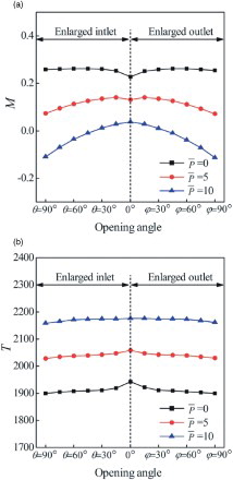
For the alternative pumps, types in which θ and ϕ vary from 0° to 90° with an increment of 15° were chosen to be simulated. Cases with and Re = 1, Re = 5, and Re = 10 are considered. The configuration with an opening angle of 0° generates the lowest mass flow rate ((a)). For pumps with an enlarged inlet and outlet, a higher mass flow rate is obtained. Meanwhile, the configuration with θ = 60° generates the highest M under all three Reynolds numbers. Compared to the standard configuration, the mass flow rate increases by about 17% when Re = 1.
Figure 3. Pump performance with different Reynolds numbers: (a) dimensionless mass flow rate and (b) dimensionless driving power.
For pumps with an enlarged inlet, the mass flow rate increases with θ when it is less than 60°. When θ is greater than 60°, the mass flow rate decreases with the further increase of the opening angle. Therefore, it can be deduced that an exact opening angle of between θ = 30° and θ = 90° exists for the peak value of M. It should also be noted that while θ is greater than 60°, the reduction of M slows down and higher values M can be obtained for larger Reynolds numbers. For pumps with an enlarged outlet, a higher Reynolds number results in a lower mass flow rate. After reaching the peak value at ϕ = 45°, the mass flow rate drops more rapidly with the further increase of the opening angle. Overall, pumps with an enlarged inlet generate larger values of M than those with an enlarged outlet when θ equals ϕ.
The pump with a 0° opening angle features the highest driving power ((b)). As θ and ϕ increase, less energy consumption is needed. This indicates that with an enlarged inlet or outlet area, a viscous pump can be designed to be more energy efficient. Moreover, as the Reynolds number increases, the dimensionless driving power also grows. An explanation for this is that for a higher rotor speed, a larger velocity gradient is generated around the rotor surface. Therefore, a stronger shear force is induced to consume more power. shows very steep variations of M and T for θ and ϕ in the region of 0–30°. For a small opening angle, the vortex which hinders the flow is not formed. The enlargement of the inlet or outlet directly contributes to the expansion of the effective flow passage in the pump. The fluid flows more smoothly around the rotor. As a consequence, with a slight increase of θ and ϕ, step variation of M and T is induced.
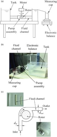
A qualitative experiment was conducted to validate the enhancement of mass transfer ability by enlarging the inlet or outlet area. (a) shows the schematic of the test rig and (b) presents the photo of experimental apparatus. In (c), a cylinder rotor is integrated into the L-shaped pump assembly. The diameter and height of the rotor are 20 mm and 7 mm, respectively. To change the cross-sectional area of the inlet or outlet channel, pipes with diameters of 2 mm, 4 mm and 6 mm were employed. The working fluid was water. The fluid volume was measured with a measuring cup and the fluid weight was measured with an electronic balance. The volumetric flow rate was checked by calculating the density and weight of the working fluid. The angular velocity of the rotor was constant. The water storage capacity of the tank was large, thus the liquid level only dropped slightly during the experiment. For each case, the experiment was conducted three times and the final flow rate was obtained by averaging the measured values.
Figure 4. The experimental apparatus: (a) schematic diagram, (b) test rig, and (c) pump assembly schematic.
presents the experimental results. In (a), the diameter of the inlet pipe varies from 2 mm to 6 mm, while the diameter of the outlet pipe is constant. The cross section of the inlet area varies linearly with . When the outlet area is constant, a higher flow rate can be obtained with a larger inlet area. The variation of the flow rate is not linear. With the increase of
, the growth of the flow rate becomes slower. Furthermore, when dout = 4 mm and din increases from 4 mm to 6 mm, the slope of the flow rate is low. It seems that a further increase in the inlet area would markedly not enhance the flow rate. In (b), the inlet area is fixed and the outlet area is enlarged. A similar flow rate variation is found. However, it should be noted that when dout = 2 mm, a larger inlet pipe of din = 6 mm does not produce as high a flow rate as that for a smaller inlet pipe of din = 4 mm.
Figure 5. Measured flow rate (a) with a constant outlet area and (b) with a constant inlet area.
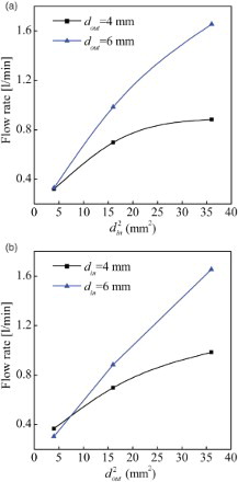
The trend in is similar to that shown in . A higher flow rate can be achieved with an expanded inlet or outlet area, but to some extent the enhancement function is limited. A larger flow channel is not meant to produce a higher flow rate in some cases.
In , cases with Re = 1 and = 0,
= 5, and
= 10 are studied. (a) presents the variation of M for different pump structures; it indicates that for a higher pressure load, a lower mass flow rate is obtained. When a higher back pressure is imposed at the pump exit, the fluid flow is restrained in the passage and less fluid is transported. For a zero pressure load, the standard L-shaped housed pump generates the lowest mass flow rate, but as the pressure load increases to 10, it gains the highest value of M. Under a high pressure load, the mass flow rate drops dramatically for pumps with a large opening angle. In some cases, a negative mass flow rate occurs. The rotor can hardly displace fluid against the high back pressure and the fluid is conversely pumped out from the inlet area. This indicates that the promotion of the mass flow rate is less obvious for high load pressures.
Figure 6. Pump performance under different pressure loads: (a) dimensionless mass flow rate and (b) dimensionless driving power.
For a larger pressure load, higher driving power is needed for the pumps to operate ((b)). In the case of zero pressure, the driving power of pumps with a small opening angle is obviously higher. However, the gap in driving power among all types reduces as the pressure load increases to 10. This reveals that pumps with a small opening angle are more stable for operating against the back load.
3.2 Influence of the Reynolds number and pressure load
The Reynolds number and the pressure load are sensitive micro viscous pump operating parameters. The effects of these parameters on the working performance is further discussed in this section. Pmp configurations with θ = 0°and θ = 30° are picked to be emphatically studied.
presents the effect of different Reynolds numbers on the working performance. The range of the Reynolds number is the same as that studied by Sharatchandra et al. (Citation1997); it assures that the pump is still working effectively and that the slip effects can be neglected. Among the whole range of Reynolds numbers tested, the pump with θ = 30° generated a higher mass flow rate than the standard type. A larger descending rate of M can be found for the pump with θ = 30°. As Re increases from 1 to 100, M decreases from 0.260 to 0.210 for the pump with an enlarged inlet, while M decreases from 0.228 to 0.184 for the standard type.
Figure 7. Impact of the Reynolds number on pump performance.
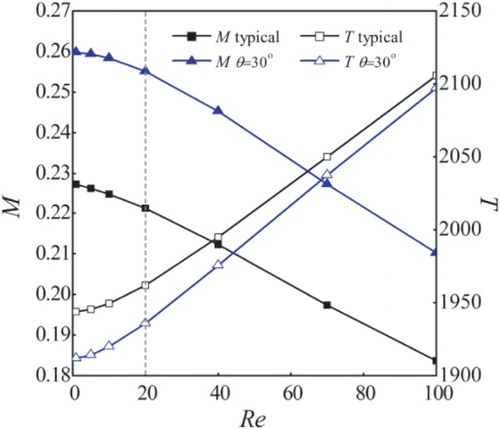
Within the whole range of Reynolds numbers, the standard pump consumes more driving power and T increases with Re. This indicates that for a larger Reynolds number, the pump becomes more energy-intensive. With the increase in Re, the gap in T between the two types is reduced. When Re reaches 100, the gap is nearly eliminated. This shows that the pump with an enlarged inlet is more susceptible to changes in the Reynolds number.
Moreover, the mass flow rate and driving power change nonlinearly with Reynolds numbers under 20 and the change rate is relatively slow. When the Reynolds number exceeds 20, the mass flow rate and driving power vary almost linearly with the Reynolds number and the change is rapid.
illustrates the influence of the pressure load on M and T for Re = 1 and Re = 10. In (a), the dimensionless mass flow rate of the two pumps decreases with the pressure load. For Re = 1, the pump with θ = 30° generates a higher mass flow rate when the pressure load is low, but as exceeds 5.7, a higher M is obtained by the standard type. As the pressure load increase from 0 to 10, the M of the pump with θ = 30° decreases from 0.260 to 0.012, while the M of the standard pump varies from 0.228 to 0.036. The decreasing slope of the alternative pump is steeper. It seems that the pump with θ = 30° is more susceptible to changes in pressure load. For a high Reynolds number Re = 10, the rate of descent is much lower and the pump with θ = 30° gets a larger mass flow rate within the whole pressure range. This indicates that the impact of the pressure load can be weakened under a high Reynolds number.
Figure 8. Impact of the pressure load on pump performance: (a) dimensionless mass flow rate and (b) dimensionless driving power.
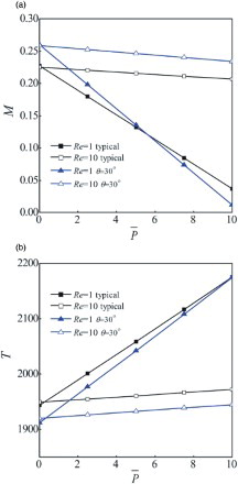
In (b), the dimensionless driving power of the two pumps increases with the pressure load. For a low Reynolds number Re = 1, the pump with θ = 30° needs less driving power when is less than 10. When
exceeds 10, it can be forecast that the standard pump will consume less driving power. For a high Reynolds number Re = 10, the increase in driving power is slower and the lines representing the two pumps are almost parallel. The sensitivity to pressure load is reduced under a higher Reynolds number.
3.3 Flow patterns and vortex structures
Despite the analysis of the working performance, the flow field of the viscous pump has not been explored. The flow dynamical behavior can help to reveal the underlying working mechanism of the viscous pump and interpret its working performance.
presents the flow streamlines for pumps with θ = 0°, θ = 30°, θ = 60° and θ = 90°, along with Re = 1 and . For the standard L-shaped housed pump, the fluid flows smoothly from the upstream region to the downstream region and changes its direction between the rotor and the outer cambered channel. For the pump with θ = 30°, a small vortex emerges near the outer channel at the upstream region. As θ increases to 60°, the upstream vortex grows larger. For the pump with θ = 90°, the vortex continues to grow and occupies almost two thirds of the upstream region.
Figure 9. Streamlines for pumps with different inlet opening angles.
Apparently, enlargement of the inlet expands the nominal flow passage for the fluid. However, with an increase in the inlet opening angle, the vortex develops and reduces the effective flow passage. Thus, the pump with a large opening angle is not bound to achieve a higher mass flow rate. This can also be validated in . For pumps with θ = 30° and θ = 60°, the vortex cannot counteract the enhancement function of the enlarged inlet area. The mass flow rate increases and is larger than that of the standard type. For the pump with θ = 90°, the vortex extends and its reduction function overtakes. As a consequence, the mass flow rate is reduced.
The flow patterns of the pump with θ = 30° under different conditions are depicted in . For a zero pressure load and Re = 1, a small vortex emerges near the outer channel at the upstream region. For Re = 10, the streamline is smooth and no obvious vortex forms in the flow passage. When Re increases to 40, a vortex appears near the outer channel at the downstream region. Combined with the analysis in , the increase in the Reynolds number induces flow structure change as well as shrinking the effective flow passage. Therefore, the mass flow rate is reduced.
Figure 10. Flow patterns for the pump with θ = 30°.
For a constant Reynolds number Re = 1, the streamline pattern changes dramatically with the pressure load. For a pressure load of , two asymmetrical vortexes form on the upstream and downstream sides of the rotor. The upstream vortex is larger than the downstream vortex and both of these vortexes are surrounded by an even larger recirculation vortex adjacent to the outer cambered channel. This vortex structure was detected by Yokota et al. (Citation2006); it is considered that the combined effect of the adverse pressure gradient and the shear force on the rotor causes this vortex pattern. As the pressure load increases to 10, the vortexes further expand and the streamlines become more distorted, which induces a narrower effective flow passage for the fluid flow. Hence, as the pressure load increases, the fluid flow is hindered and a smaller mass flow rate is obtained.
also presents the flow pattern for Re = 40 and . Instead of the two asymmetrical vortexes, only a small vortex forms near the outer passage edge in the downstream region. This indicates that a higher rotor speed can reduce the expansion of vortexes under a high pressure load and helps to refine the flow structure and maintain the effective flow passage.
4 Conclusions and future work
In this paper, the working performance and flow dynamical behaviors of a viscous pump are studied. The results suggest the following:
The alternative pumps exhibit variations in working performance compared to the standard pump. A higher mass flow rate and reduced driving power can be achieved by pumps with enlarged inlet and outlet areas.
A high pressure load reduces the mass flow rate and increases the driving power. Pumps with a small opening angle are less susceptive to the Reynolds number and the pressure load.
Increasing the rotor speed helps to refine the vortex structure under a high pressure load. The adverse impact of a high pressure load is weakened and the working performance is maintained.
Complex flow structures and vortex evolution can be found in the flow channel. The flow dynamical behaviors of the viscous pump have a significant impact on the working performance.
Disclosure statement
No potential conflict of interest was reported by the authors.
Additional information
Funding
References
- Abdelgawad, M., Hassan, I., & Esmail, N. (2004). Transient behavior of the viscous micropump. Microscale Thermophysical Engineering, 8(8), 361–381. doi: 10.1080/10893950490516901
- Blanchard, D., & Ligrani, P. (2006). Comparisons of different viscous pumps based on physical flow behavior. Sensors and Actuators A: Physical, 126(126), 83–92. doi: 10.1016/j.sna.2005.09.022
- Blanchard, D., Ligrani, P., & Gale, B. (2005). Single-disk and double-disk viscous micropumps. Sensors and Actuators A: Physical, 122(1), 149–158. doi: 10.1016/j.sna.2005.03.072
- Blanchard, D., Ligrani, P., & Gale, B. (2006). Miniature single-disk viscous pump (Single-DVP), performance characterization. Journal of Fluids Engineering, 128(3), 602–610. doi: 10.1115/1.2175167
- Choi, H. I., Lee, Y., Choi, D. H., & Maeng, J. S. (2010). Design optimization of a viscous micropump with two rotating cylinders for maximizing efficiency. Structural and Multidisciplinary Optimization, 40(1-6), 537–548. doi: 10.1007/s00158-009-0373-5
- Decourtye, D., Sen, M., & Gad-El-Hak, M. (1998). Analysis of viscous micropumps and microturbines. International Journal of Computational Fluid Dynamics, 10(1), 13–25. doi: 10.1080/10618569808961670
- Geipel, A., Doll, A., Jantscheff, P., Esser, N., Massing, U., & Woias, P. (2007). A novel two-stage backpressure-independent micropump: Modeling and characterization. Journal of Micromechanics and Microengineering, 17(5), 949–959. doi: 10.1088/0960-1317/17/5/015
- Haik, Y., Kilani, M., Hendrix, J., Rifai, O. A., & Galambos, P. (2007). Flow field analysis in a spiral viscous micropump. Microfluidics and Nanofluidics, 3(5), 527–535. doi: 10.1007/s10404-006-0143-2
- Iverson, B. D., & Garimella, S. V. (2008). Recent advances in microscale pumping technologies: A review and evaluation. Microfluidics and Nanofluidics, 5(2), 145–174. doi: 10.1007/s10404-008-0266-8
- Jian, Y., Si, D., Chang, L., & Liu, Q. (2015). Transient rotating electromagnetohydrodynamic micropumps between two infinite microparallel plates. Chemical Engineering Science, 134, 12–22. doi: 10.1016/j.ces.2015.04.036
- Kang, D. J. (2014). Effects of channel curvature on the performance of viscous micro-pumps. Journal of Mechanical Science and Technology, 28(9), 3733–3740. doi: 10.1007/s12206-014-0834-7
- Kilani, M. I., & Al-Salaymeh, A. (2007). Simple analytical expressions for the flow performance of a spiral-channel viscous micropump. Fluid Dynamics Research, 39(8), 632–646. doi: 10.1016/j.fluiddyn.2007.02.002
- Kim, J. H., Na, K. H., Kang, C. H., & Kim, Y. S. (2005). A disposable thermopneumatic-actuated micropump stacked with PDMS layers and ITO-coated glass. Sensors and Actuators A: Physical, 120(2), 365–369. doi: 10.1016/j.sna.2004.12.024
- Laser, D. J., & Santiago, J. G. (2004). A review of micropumps. Journal of Micromechanics and Microengineering, 14(6), R35–R64. doi: 10.1088/0960-1317/14/6/R01
- Leontidis, V., Chen, J., Baldas, L., & Colin, S. (2014). Numerical design of a knudsen pump with curved channels operating in the slip flow regime. Heat and Mass Transfer, 50(8), 1065–1080. doi: 10.1007/s00231-014-1314-4
- Lu, J., & Ding, J. (2010). Flow dynamical behaviors and characteristics of aligned and staggered viscous pumps. International Journal of Heat and Mass Transfer, 53, 2092–2099. doi: 10.1016/j.ijheatmasstransfer.2009.12.046
- Lu, J., Jing, D., Yang, J., & Yang, X. (2014). Steady dynamical behaviors of novel viscous pump with groove under the rotor. International Journal of Heat and Mass Transfer, 73(4), 170–176. doi: 10.1016/j.ijheatmasstransfer.2014.02.004
- Mainland, M., & Green, I. (1992). Analysis and optimization of semi-circular and straight lobe viscous pumps. Journal of Tribology, 114(3), 515–521. doi: 10.1115/1.2920913
- Martín-Alcántara, A., Sanmiguel-Rojas, E., & Fernandez-Feria, R. (2015). On the development of lift and drag in a rotating and translating cylinder. Journal of Fluids and Structures, 54, 868–885. doi: 10.1016/j.jfluidstructs.2015.02.002
- Phutthavong, P., & Hassan, I. (2004). Transient performance of flow over a rotating object placed eccentrically inside a microchannel?numerical study. Microfluidics and Nanofluidics, 1(1), 71–85. doi: 10.1007/s10404-004-0006-7
- Pramod, K., & Sen, A. K. (2014). Flow and heat transfer analysis of an electro-osmotic flow micropump for chip cooling. Journal of Electronic Packaging, 136(3), 031012. doi: 10.1115/1.4027657
- Rao, A., Thompson, M. C., Leweke, T., & Hourigan, K. (2015). Flow past a rotating cylinder translating at different gap heights along a wall. Journal of Fluids and Structures, 57, 314–330. doi: 10.1016/j.jfluidstructs.2015.06.015
- Sen, M., Wajerski, D., & Gad-el-Hak, M. (1996). A novel pump for MEMS applications. Journal of Fluids Engineering, 118(3), 624–627. doi: 10.1115/1.2817807
- Sharatchandra, M. C., Sen, M., & Gad-el-Hak, M. (1997). Navier-Stokes simulations of a novel viscous pump. Journal of Fluids Engineering, 119(2), 372–382. doi: 10.1115/1.2819144
- Sharatchandra, M. C., Sen, M., & Gad-el-Hak, M. (1998). Thermal aspects of a novel viscous pump. Journal of Heat Transfer, 120(1), 99–107. doi: 10.1115/1.2830071
- Silva, A. K., Kobayashi, M. H., & Coimbra, C. F. M. (2007). Optimal theoretical design of 2-D microscale viscous pumps for maximum mass flow rate and minimum power consumption. International Journal of Heat and Fluid Flow, 28(3), 526–536. doi: 10.1016/j.ijheatfluidflow.2006.07.005
- Wang, B. T., Okamoto, K., Yamaguchi, K., & Teramoto, S. (2014). Loss mechanisms in shear-force pump with multiple co-rotating disks. Journal of Fluids Engineering, 136(8), 52–68. doi: 10.1115/1.4026585
- Yin, Z., & Prosperetti, A. (2005). ‘Blinking bubble’ micropump with microfabricated heaters. Journal of Micromechanics and Microengineering, 15(9), 1683–1691. doi: 10.1088/0960-1317/15/9/010
- Yokota, K., Sato, K., & Itoh, M. (2006). Model experiment, numerical simulation and theoretical analysis on the characteristics of a viscous micropump using a cylindrical rotor in a rectangular duct. JSME International Journal Series B, 49, 393–400. doi: 10.1299/jsmeb.49.393
- Yun, K. S., Cho, I. J., Bu, J. U., Kim, C. J., & Yoon, E. (2002). A surface-tension driven micropump for low-voltage and low-power operations. Journal of Microelectromechanical Systems, 11(5), 454–461. doi: 10.1109/JMEMS.2002.803286
- Zhang, C., Da, X., & Li, Y. (2007). Micropumps, microvalves, and micromixers within PCR microfluidic chips: advances and trends. Biotechnology Advances, 25(5), 483–514. doi: 10.1016/j.biotechadv.2007.05.003
- Zhang, T., & Wang, Q. M. (2005). Valveless piezoelectric micropump for fuel delivery in direct methanol fuel cell (DMFC) devices. Journal of Power Sources, 140(1), 72–80. doi: 10.1016/j.jpowsour.2004.07.026