
ABSTRACT
Radial diffusers can improve the flow uniformity in pumps and affect the hydraulic performance of centrifugal pumps directly. The diffusion coefficient d is an important parameter in fluid machinery but it has seldom been used in the diffuser design of single-stage centrifugal pumps. To improve the design method of radial diffuser use in centrifugal pumps, the diffusion coefficient was introduced into the design of radial diffusers based on a single-arc hydraulic design method and it was found that the vane outlet angle, vane outlet thickness and vane number have a significant impact on the design results. A single-stage centrifugal pump with a radial diffuser was selected as the research model. The inner flow was simulated using the commercial computational fluid dynamics (CFD) program CFX and verified by experiment. The results indicate that the head and efficiency of the pump are best when the vane outlet angle is 6°. The flow area decreases and the flow velocity at radial diffuser outlet increase when the outlet thickness is greater than 2 mm. The hydraulic loss is minimum and the head and efficiency are better when the vane number is 8 at different flow rates. So, the optimal range of the diffusion coefficient for the model pump is around 1.6 to 2. The study indicates that it is feasible to design radial diffusers according to the diffusion coefficient.
Nomenclature
| Nomenclature | ||
| β1 | = | Inlet angle of impeller (°) |
| β2 | = | Outlet angle of impeller (°) |
| β3 | = | Inlet angle of radial diffuser (°) |
| β4 | = | Outlet angle of radial diffuser (°) |
| b2 | = | Outlet width of impeller (mm) |
| b3 | = | Inlet width of radial diffuser (mm) |
| b4 | = | Outlet width of radial diffuser (mm) |
| D2 | = | Outlet diameter of impeller (mm) |
| D3 | = | Inlet diameter of radial diffuser (mm) |
| D4 | = | Outlet diameter of radial diffuser (mm) |
| H | = | Head (m) |
| n | = | Rotational speed (r/min) |
| ns | = | Specific speed ( |
| N | = | A positive integer |
| P | = | Total pressure (Pa) |
| Q | = | Flow rate (m3/h) |
| T | = | Vane outlet thickness of radial diffuser (mm) |
| V | = | Absolute velocity (m/s) |
| ZB | = | Vane number of impeller |
| ZR | = | Vane number of radial diffuser |
1. Introduction
The radial diffuser is an important collector in centrifugal pumps and is widely used in large single-stage and multistage pumps. In large single-stage pumps, although the radial diffuser does not have return guide vanes it still can make the impeller outlet flow uniform. Recently, with the rapid development of modern industry, the application of large centrifugal pumps has become more diverse and the use of radial diffusers in large single-stage centrifugal pumps to improve flow uniformity is also more widespread. To some extent, radial diffusers can have a significant impact on the performance of large single-stage centrifugal pumps.
The performance of diffusers has been an important field of research for many years. Reneau, Johnston, and Kline (Citation1967) found that the performance of 2D diffusers is greatly affected by the inlet conditions. High recovery occurs at high area ratios (up to 5) and the minimum head loss occurs at 2θ < 7 deg.
Much attention is still devoted to research on radial diffusers (Lugovaya, Olshtynsky, Rudenko, & Tverdokhleb, Citation2012; F. Shi, Citation2001). Goto and Zangeneh (Citation2002) presented a new approach to optimizing a pump diffuser based on a three-dimensional inverse design method and computational fluid dynamics (CFD). Other researchers designed a twisted return guide vane for a submersible multistage pump, the results of their work demonstrating that return guide vanes with a twisted inlet can reduce the flow loss in radial diffusers. The results show that the pressure changes little at the helix section along the direction of the flow then increases more and more at the diffuser section and hits its maximum at the end of the diffuser section (W. D. Shi, Zhang, & Lu, Citation2006; J. C. Zhang & Li, Citation2006). Zhou, Shi, Lu, Xu, and Wang (Citation2011) optimized the guide vane by using an orthogonal test method and found that the wrap angle and inlet angle of the radial diffuser have a greater impact on the pump head and efficiency. The results indicate that the three-dimensional guide vane has a smaller hydraulic loss and a higher pressure conversion capacity. And at the same time, they studied the performance of the deep-well centrifugal pump with the new designed guide vane (Zhou, Shi, & Lu, Citation2011).
Liu, Cui, Tan, Wu, and Xu (Citation2013) studied the effect that the relative position between the guide vane and the volute tongue has on the characteristics of a centrifugal pump and found that the head and efficiency are at maximum when the angle between the guide vane and tongue is about 20°. Hou, Zhang, Li, Zhou, and Wang (Citation2014) simulated the full flow in a centrifugal pump and found that pre-whirl regulation at the inlet of the guide vane can improve the hydraulic performance of the pump at off-design conditions. In order to study the effect of the outlet diameter of radial diffusers on the performance of centrifugal pumps, Jiang, Li, and Liu (Citation2014) simulated the flow in three pumps and found that the performance of a pump with a diffuser of smaller outlet diameter is better under all operating conditions.
Recently, CFD has been widely used to research pump performance. Huang, Mou, and Zheng (Citation2012) optimized the match between the guide vane outlet and the impeller inlet in a multistage centrifugal pump using CFD and found that the static pressure is highest when the outlet angle of the guide vane is 90°. Alemi, Nourbakhsh, Raisee, and Najafi (Citation2015) used CFD to study the effect of casings and found that the triple-volute is the most appropriate volute geometry under off-design conditions.
Many studies have also been carried out on radial diffusers in multistage pumps. Some studies presented a numerical investigation of the water flow in the first stage of a two-stage centrifuge pump (Segala et al., Citation2011; Stel et al., Citation2013). Q. H. Zhang et al. (Citation2013) designed a circumferential crankle guide vane based on the twisted centrifugal impeller design method to match the compact structure of multistage pumps.
Experimental method was widely used into researches of internal flow for verifying the reliability of the numerical simulation. Sinha and Katz (Citation1999) adopted particle image velocimetry measurements to identify the unsteady flow structures and turbulence in a centrifugal pump with a vane diffuser.
The diffusion coefficient d is an important parameter in both fluid machinery and pump design. Although many studies have investigated the design of radial diffusers for pumps with respect to the diffusion coefficient d, most of them focus on the radial diffusers in multistage pumps, which have return guide vanes. In the present work, a design method for a radial diffuser without return guide vanes for single-stage centrifugal pumps was constructed and studied. First, the diffusion coefficient was introduced into the design of a radial diffuser without return guide vanes and the single-arc hydraulic design method was established. Next, the effects that important parameters – such as the vane outlet angle, vane outlet thickness and vane number of the radial diffuser – have on the performance of centrifugal pumps were analyzed using numerical methods. Finally, the design method was verified by experiments. The research in this paper provides preliminary reference to the diffuser design according to the diffusion coefficient d.
2. The design of radial diffusers
The structure of a single-stage centrifugal pump with a radial diffuser is similar to that of a centrifugal compressor. The effect of a radial diffuser on a single-stage centrifugal pump is similar to the effect that a vane diffuser has on a centrifugal compressor. In compressors, the vane diffuser is considered to be a ring cascade that transfers most of the kinetic energy at the inlet impeller into pressure energy, and the diffusion coefficient is an important parameter for the vane diffuser design. For incompressible fluid, the diffusion coefficient is defined by the area ratio A2/A1 or the velocity ratio V1/V2 between the inlet and outlet of the vane diffuser. Radial diffusers in single-stage centrifugal pumps also reduce the velocity and increases the pressure, so the diffusion coefficient was introduced to evaluate the performance of the radial diffuser. The diffusion coefficient is defined as:
(1)
where V3 is the inlet velocity of the radial diffuser and V4 is the outlet velocity of the radial diffuser. According to this definition, the bigger the diffusion coefficient, the better the performance of the radial diffuser.
One-dimensional theory was used to deduce the diffusion coefficient of radial diffusers for single-stage centrifugal pumps. The velocity triangles at the impeller outlet and the inlet and outlet of the radial diffuser are shown in , and the deduction process is detailed below.
Figure 1. Velocity triangle at impeller outlet, inlet and outlet of diffuser.
The circumferential velocity U2 at the impeller outlet is:
(2)
The meridional velocity Vm2 at the impeller outlet is:
(3)
where ϕ2 is the blockage factor at the impeller outlet.
The circumferential component of the absolute velocity VU2 at the impeller outlet is
(4)
The circumferential component of the absolute velocity VU3 at the diffuser inlet is defined as:
(5)
The meridional velocity Vm3 at the diffuser inlet is:
(6)
where ϕ3 is the blockage factor at the diffuser inlet and can be written as:
(7)
The absolute velocity V3 at the diffuser inlet is:
(8)
The meridional velocity Vm4 at the diffuser outlet is:
(9)
where ϕ4 is the blockage factor at the diffuser outlet.
The absolute velocity V4 at the diffuser outlet is:
(10)
where β4 is the outlet angle of the radial diffuser.
Based on with Equations (8) and (10), the diffusion coefficient d can be written as:
(11)
As shown in Equation (11), the diffusion coefficient d of the radial diffuser is related to the design parameters of centrifugal pumps and the structural parameters of the impeller and radial diffuser, so it can be used as the design criterion for the radial diffuser.
In order to display the relations between β4, b4, ZR and d directly, based on Equation (7), Equation (11) can be written as:
(12)
where t is defined as the vane outlet thickness instead of b4.
Through careful analysis of Equation (12), it can be seen that the vane outlet angle β4 and the blockage factor at the outlet ϕ4 of the radial diffuser have a significant impact on the diffusion coefficient d. So, the vane outlet angle, the vane outlet thickness and the vane number that influences the blockage factor at the vane outlet are meticulously investigated in this paper.
3. The validation model
3.1. The parameters and structure of the model
A single-stage, single-suction centrifugal pump with a radial diffuser was used as the research model to validate the above design method. The model pump consists of an impeller, a radial diffuser and a volute. The hydraulic structure is shown in .
Figure 2. Hydraulic structure of the model pump.
The flow rate of the model pump Q = 32 m3/h, the head H = 7.5 m, the efficiency η = 75% and the rotating speed n = 1450 r/min, with the specific speed ns = 110. The main geometric parameters of the model pump are summarized in .
Table 1. Main geometric parameters.
3.2. The design of the new radial diffuser
Keeping the outlet and inlet diameters of the original radial diffuser constant and using the diffusion coefficient as the design criterion, the single-arc hydraulic design method for the radial diffuser (as shown in ) is presented based on the traditional method. In this new method, the pressure side and suction side are two different sides of the radial diffuser are designed to be a single arc which can easily control the vane shape. Also, this new method can make the design and production of the radial diffuser more fast and convenient.
Figure 3. Single-arc design method for the radial diffuser.
4. Numerical simulation
Numerical simulation was used to study the effect of the vane outlet angle β4, the vane outlet thickness t and the vane number ZR.
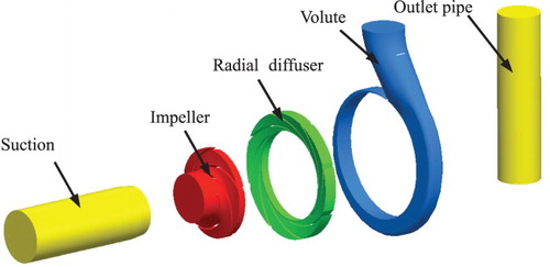
First, Pro/E, a commercial 3D software, was used to build and assemble the computational domains. As shown in , the whole computational domain consists of a suction chamber, a radial diffuser, an impeller, a volute and an outlet pipe. The outlet pipe can reduce the effect of the boundary conditions on the inner flow and its length is four times that of the pump outlet diameter.
Figure 4. 3D model of the flow field calculation domain.
Second, Gambit, a mesh generating software, was used to generate the mesh of the computational domain. The suction chamber, radial diffuser and outlet domain were generated as hexahedral cells, while the impeller and volute were generated as a tetrahedral mesh due to their complex structure. To check the mesh size independence, six grid topologies were generated. The head and efficiency under the design flow rate were used as the criteria and the simulation results () show that the maximum difference of the heads is just 0.16% and that of the efficiencies is just 0.25%. Therefore, taking the calculation resources and CFD post-processing into consideration, 4 was selected as the number for the mesh size.
Table 2. The independence check of the mesh.
Finally, CFX, a commercial computational fluid dynamics code, was applied to perform a steady numerical simulation of the internal flow in the model pump and the re-normalisation group k-ε model was selected as the turbulence model. The impeller was set to be the rotating domain and its speed was set to 1450 r/min with the other domains left static. There were four domain interfaces in total and the interface model was set to be a general connection. The total pressure was used as the inlet boundary condition and the inlet pressure was 1 atm. The outlet was set to be a mass flow and the velocity was calculated by the flow rate. The wall boundary was set to be a no-slip boundary and the roughness of all surfaces was set as 0.025 mm.
5. Results and analysis
5.1. The effect of the vane outlet angle on performance
Six radial diffusers with different vane outlet angles were designed using the single-arc hydraulic design method. The vane outlet angle β4 of the radial diffuser was set as 3°, 6°, 10°, 15°, 25° and 40° and the diffusion coefficient d was set as 1.02, 2.05, 3.40, 5.07, 8.27 and 12.85, respectively according to Equation (12). The internal flow in the model pump under 0.6Qd, 0.8Qd, 1.0Qd, 1.2Qd and 1.4Qd was simulated and the prediction performance curves are shown in Figures and .
Figure 5. H-Q curves for different vane outlet angles β4.
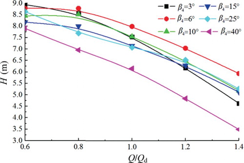
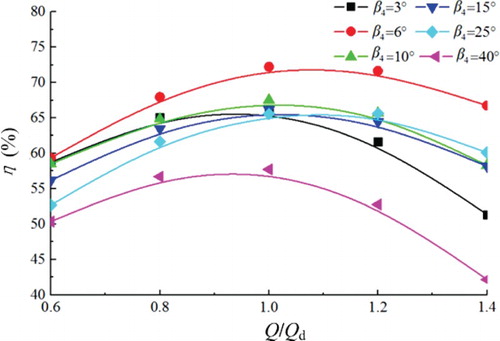
Figure 6. η-Q curves for different vane outlet angles β4.
It can be seen from that for different values of the vane outlet angle β4 the head is obviously different under the same flow rate. With an increase in flow rate the difference of the head curves becomes greater. At the design flow rate, the maximum head difference is 1.83 m. Under all operating conditions, the head is at maximum when the vane outlet angle β4 is 6° and the head is at minimum when the β4 is 40°. The head is close to the design requirement when the vane outlet angle β4 is at 6° at the design flow rate.
shows the efficiency curves of the model pump under different radial diffuser vane outlet angles β4. The shape of each efficiency curve is very similar and the maximum of each efficiency curve is close to the 1.0Qd condition, but under the same flow rate the efficiency of each curve has significant differences. With an increase in flow rate the efficiency difference between the curves becomes greater, with a maximum efficiency difference of 14.5% at the design condition. Under all operating conditions, the efficiency is at maximum when β4 = 6° and minimum when β4 = 40°.
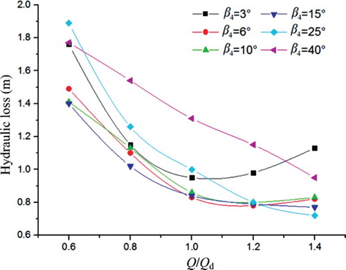
The hydraulic loss in the radial diffuser under different vane outlet angles is shown in . The hydraulic loss in the diffuser can be obtained by Δh = (Pout − Pin)/(ρg), where Pout is the outlet pressure and Pin is the inlet pressure. For all hydraulic loss curves under different vane outlet angles β4 it can be seen that the hydraulic loss gradually decreases as the flow increases from 0.6Qd to 1.0Qd. From 1.0Qd to 1.2Qd, the hydraulic loss decreases when β4 is greater than or equal to 15° but increases when β4 is less than 15°. It can also be observed that the hydraulic loss always increases when the vane outlet angle β4 is too small (3°) or too big (40°). The explanation for this is that smaller values of β4 result in a greater dynamic loss while bigger values of β4 lead to a greater diffusion loss. At the design flow rate, the hydraulic loss is at minimum when the vane outlet angle β4 = 6°.
Figure 7. Hydraulic loss in the radial diffuser for different vane outlet angles β4.
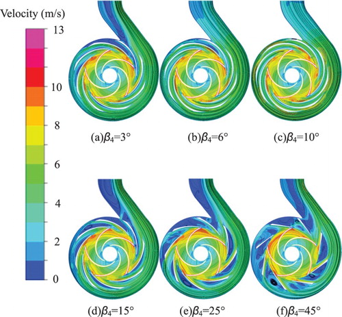
At the design flow rate, the distribution of absolute velocity in the middle plane of the model pump is shown in . The velocity at the impeller outlet is at maximum due to the rotation of the impeller. The diffusion coefficient d is just 1.02 when the vane outlet angle β4 = 3°. In this case, the velocity at the radial diffuser outlet is high and the flow field is very smooth. When the vane outlet angle β4 is 6° or 10°, the velocity at the radial diffusion outlet decreases as the diffusion coefficient d increases, and the flow field is still good. When the vane outlet angle β4 is greater than10° there are a lot of low-velocity areas in the radial diffuser and volute with an increase in the diffusion coefficient d. Under these circumstances, unsteady flow occurs easily, such as flow separation and back flow.
Figure 8. Velocity distribution in the pump middle plane at the design flow rate for: (a) β4 = 3°, (b) β4 = 6°, (c) β4 = 10°, (d) β4 = 15°, (e) β4 = 25°, and (f) β4 = 45°.
At the design condition, the total efficiency in the pump and the integral hydraulic loss in the radial diffuser and the volute are shown in . As can be seen, the total hydraulic loss decreases as the diffusion coefficient increases from 1.02 to 2.05, then gradually increases as it changes from 2.05 to 8.27, and finally sharply increases beyond the value of 8.27. The total efficiency change in the pump corresponds to the integral hydraulic loss in the radial diffuser and volute.
Figure 9. Total efficiency in the pump and the integral hydraulic loss in the radial diffuser and the volute at the design condition.
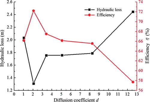
When the diffusion coefficient is 1.02, the friction loss in the diffusers is large because of the narrow channel and the high outlet velocity of the radial diffuser. When the diffusion coefficient is 2.05, the radial diffuser plays a role in reducing the velocity and increasing the pressure, which leads to a decrease in the flow rate in the volute. Consequently, the hydraulic loss decreases and the efficiency increases at the same time. With future increases in the diffusion coefficient, the diffusion of the radial diffuser channel gets bigger and a low-velocity area appears on the suction surface and in the volute diffuse section, meaning that the hydraulic loss increases and the efficiency decreases. As the diffusion coefficient continues to increase, a vortex occurs in the radial channel and the efficiency decreases sharply. To summarize, there is a suitable range for the diffusion coefficient d. The radial diffuser loses the effect of reducing the velocity and increasing the pressure if d is too small, and the diffusion and flow loss increase if it is too large. Based on the research model, it is best for the diffusion coefficient d to stay around a value of 2 for different vane outlet angles.
According to the above analysis, it can be concluded that a vane outlet angle β4 of 6° is the best for the model pump.
5.2. The effect of the vane outlet thickness on performance
Based on a vane outlet angle β4 of 6°, four radial diffusers were designed with a vane outlet thickness t of 2 mm, 5 mm, 8 mm and 10 mm and a diffusion coefficient d of 1.63, 1.19, 0.76 and 0.54, respectively according to Equation (12).
The internal flow in the pump was simulated for the four different radial diffusers under 0.6Qd, 0.8Qd, 1.0Qd, 1.2Qd and 1.4Qd. The predicted curves of head and efficiency are shown in Figures and .
Figure 10. H-Q curves for different vane outlet thicknesses t.
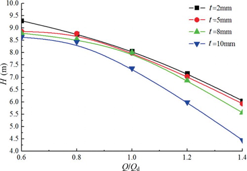
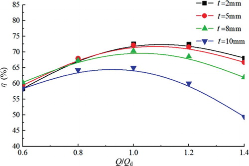
Figure 11. η-Q curves for different vane outlet thicknesses t.
As is shown in the , although the values of vane outlet thickness t are different, the head on each curve gets smaller as the flow rate increases. However, under the same flow rate, the head shows significant differences for different head curves, especially under larger or smaller flow rates. At 1.4Qd, the head difference is at maximum and at about 1.7 m. Under all operating conditions, the head is at maximum when the vane outlet thickness t = 2 mm and decreases as the vane outlet thickness t increases and the diffusion coefficient d decreases.
shows the efficiency curves for different values of vane outlet thickness t. It can be seen that the best efficiency occurs close to 1.0Qd for each efficiency curve. At 0.6Qd the efficiency difference between these curves is the smallest, about 3%, and the difference becomes gradually greater with an increase in flow rate. At 1.4Qd, the efficiency difference is about 20% and from 0.8Qd to 1.4Qd, the efficiency is highest when the vane outlet thickness t = 2 mm and it decreases as the vane outlet thickness t increases.
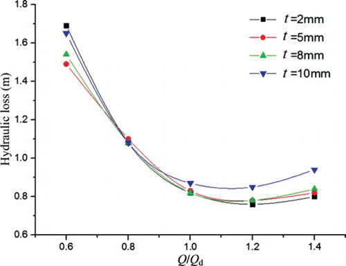
The hydraulic loss in the radial diffuser under different values of vane outlet thickness t is presented in . It can be seen that from 0.6Qd to 1.0Qd the hydraulic loss in the radial diffuser with different values of t gradually decreases, but if the flow rate increases further then the hydraulic loss increases at the same time. At a small flow rate, the main hydraulic loss in the radial diffuser is diffusion loss and this increases as the vane outlet thickness t decreases. At a large flow rate, the dynamic loss increases, which leads to an increase in the total hydraulic loss, and the dynamic loss increases as the vane outlet thickness increases. It was found that the hydraulic loss is at minimum when the vane outlet thickness t is 2 mm from 0.8Qd to 1.4Qd.
Figure 12. Hydraulic loss in the radial diffuser for different vane outlet thicknesses t.
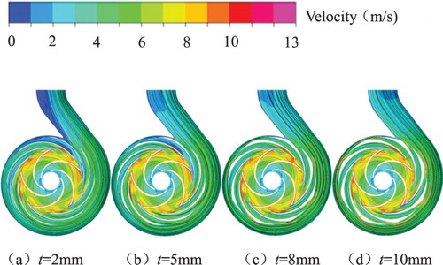
At the design flow rate, the velocity distribution in the middle pump plane is presented in . It can be clearly seen that there are low-velocity zones in the volute and radial diffuser when the vane outlet thickness t = 2 mm. With an increase in the vane outlet thickness t, the diffusion coefficient d decreases and the area of the passage also decreases, so the flow velocity in the radial diffuser outlet increases rapidly and the low-velocity zones gets smaller and then disappears, which means a large dynamic loss.
Figure 13. Velocity distribution in the pump middle plane at the design flow rate for: (a) t = 2 mm, (b) t = 5 mm, (c) t = 8 mm, and (d) t = 10 mm.
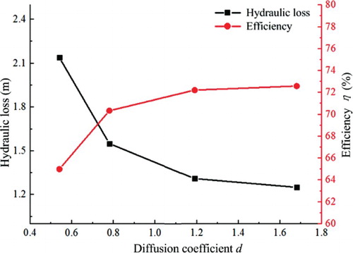
shows the total efficiency in the pump and the integral hydraulic loss in the radial diffuser and the volute. It can be seen that the hydraulic loss decreases and the pump efficiency increases as the diffusion coefficient d increases. When the diffusion coefficient is too small, the outlet velocity of the radial diffuser is high, which leads to an increase in the hydraulic loss of the volute and a decrease in pump efficiency. The outlet velocity increases as the outlet thickness increases, so the hydraulic loss of the radial diffuser and volute increase and the total efficiency of the pump decrease. Therefore, the diffusion coefficient d is best at around 1.7 for different vane outlet thicknesses.
Figure 14. Total efficiency in the pump and the integral hydraulic loss in the radial diffuser and the volute at the design condition.
Therefore, based on the above analysis, it can be concluded that the best vane outlet thickness t for this model is 2 mm.
5.3. The effect of the vane number on performance
Based on the above results, six radial diffusers with different vane numbers were designed with the same vane outlet angle β4 = 6° and vane outlet thickness t = 2 mm. The vane number was 6, 7, 8, 9, 11 and 12 and the diffusion coefficient d was 1.72, 1.67, 1.63, 1.56, 1.46 and 1.41, respectively based on Equation (12).
The internal flow in the pump with the different radial diffusers was simulated for 0.6Qd, 0.8Qd, 1.0Qd, 1.2Qd and 1.4Qd. The predicted head and efficiency curves are shown in Figures and . It can clearly be seen from the that the head on each curve gets smaller as the flow rate increases. When the vane number is 7 or 8, the heads are close to each other and all are higher than the other. The head with 6 vanes is lowest. Under all flow rates, the head difference between the maximum and minimum is 0.8 m. In , it can be seen that the head under all flow rates decreases if the vane number ZR is too big or too small.
Figure 15. H-Q curves for different vane numbers ZR.
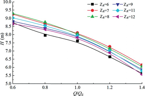
Figure 16. η-Q curves for different vane numbers ZR.
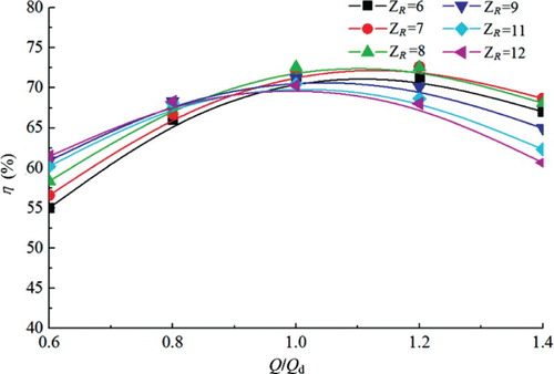
The pump efficiency curves under different vane numbers are shown in . It can be seen that the difference in efficiency is small at the design flow rate and that the maximum difference is 2%. With the flow increasing or decreasing, the difference in efficiency increases for off-design conditions. At 0.6Qd, the efficiency gradually increases as the vane number increases and the maximum difference is 6%. At 1.4Qd, the efficiency is at maximum for ZR = 7 and at minimum for ZR = 12, and the maximum difference is 8%. A vane number that is too great or too small results in reduced efficiency. From 0.9Qd to 1.1Qd, the best ZR value for the model pump is 8.
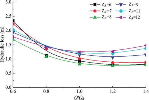
presents the hydraulic loss curves in the radial diffuser for different vane numbers. It can be seen that as the flow rate increases from 0.6Qd to 1.0Qd, the hydraulic loss on each curve decreases gradually, but if the flow rate increases further, the hydraulic loss increases. At a low flow rate, the main hydraulic loss is diffusion loss in the radial diffuser, which it increases as the vane number decreases. As the flow rate and vane number ZR increase, the diffusion coefficient d decreases, and the friction loss and dynamic loss increase as the diffusion loss decreases. Therefore, there is a minimum for hydraulic loss; it is clear that the hydraulic loss is lowest under all flow rates when the vane number ZR is 8.
Figure 17. Hydraulic loss in the radial diffuser for different vane numbers ZR.
The velocity distribution in the pump’s middle plane at the design flow rate is shown in . It can be seen that there is an obvious low-velocity zone in the radial diffuser when the vane number ZR is less than 11 and the flow velocity is small. The low-velocity zone in the radial diffuser results in a good pressure rise, but there is a large diffusion loss due to the big diffusion coefficient. When the vane number ZR is greater than 9, the low-velocity zone in the radial diffuser disappears, which means that the total velocity is very large and this leads to a large amount of friction loss and dynamic loss. So, the above theory analysis of agrees well with the flow field analysis of .
Figure 18. Velocity distribution in the pump middle plane at the design flow rate for: (a) ZR = 6, (b) ZR = 7, (c) ZR = 8, (d) ZR = 9, (e) ZR = 11, and (f) ZR = 12.
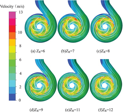
Figure 19. Total efficiency in the pump and the integral hydraulic loss in the radial diffuser and the volute at the design condition.
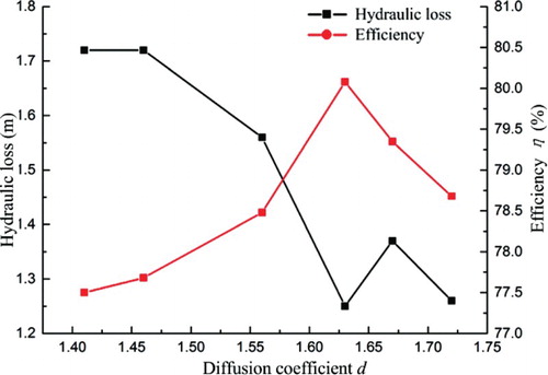
Figure 20. The design contrast between the new and old diffusers.
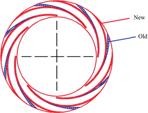
Figure 21. The new radial diffuser.
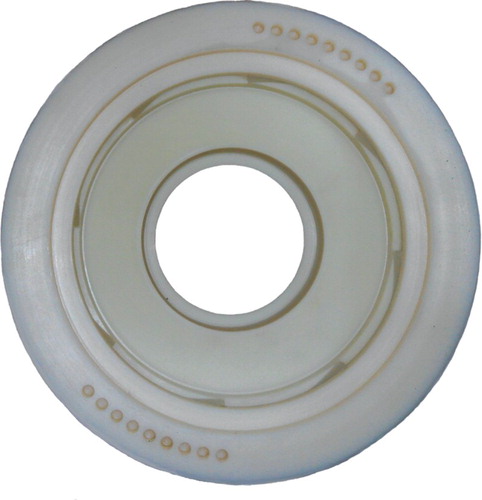
Figure 22. The model pump.
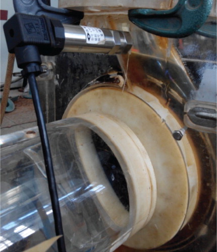
Figure 23. Sketch of the test bed.
The total efficiency in the pump and the integral hydraulic loss in the radial diffuser and the volute at the design condition are shown in . It can be seen that the hydraulic loss decreases as the diffusion coefficient d increases and reaches its minimum when d = 1.63, while the efficiency changes in accordance with the hydraulic loss. The diffusion coefficient d is large when the vane number is low, which results in an increase in diffusion loss, while the whole hydraulic loss is small because the friction loss is small. The flow becomes better as the vane number ZR increases but the friction loss also increases. Therefore, the hydraulic loss of the pump as the vane number increases (and the diffusion coefficient d decreases). Thus, it is concluded that the best diffusion coefficient is about 1.6 for different vane numbers.
In summary, based on the presented investigations, the best vane number for this model is 8.
6. Experimental verification
6.1. Experimental system
According to the numerical simulation results, a new radial diffuser was designed with a vane outlet angle β4 of 6°, a vane outlet thickness t of 2 mm and a vane number ZR of 8. The structures of the new and old radial diffusers are shown in . It can be seen that the outlet angle and outlet thickness of the new radial diffuser all get smaller and the diffusion parts become longer, which means that more kinetic energy can be transformed into pressure energy. In this case, the friction loss of the pump decreases as the velocity decreases.
In order to verify the design, the new radial diffuser () was constructed using rapid prototyping manufacturing and used in the experiment. The model pump and test rig are shown in Figures and .
As can be seen, the pump was tested in a closed test rig which consisted of the model pump, a torque meter, a motor, a pressure transfer, turbine flow meters, a pressurizer tank, a cavitation tube, a vacuum pump, piping and valves. Considering that the material of impeller is polymethylmethacrylate, whose strength is weaker compared with metal, the inverter was used to start the pump and gradually increase the speed until the rated speed was achieved. The shaft torque was measured using a torque meter with an accuracy of ±0.10%. A pressure transfer was used to measure the static pressure values at the inlet and outlet of the pump, again to an accuracy of ±0.10%. The flow rate was measured by a turbine flow meter to an accuracy of ±0.14%.
6.2. Comparisons between the simulated and experimental results
shows the performance of the model pump with the new radial diffuser. It can be seen that the head increases about 1 m under all operating conditions. The efficiency also increases to different extents, increasing 8% on average at low flow rates and 5% on average at high flow rates. The power of the pump with the new radial diffuser is less than that of the old radial diffuser at low flow rates and greater at high flow rates. The increase of the head and the efficiency results in a decrease in hydraulic loss. In summary, the experiment results indicate that it is feasible and practical to design a radial diffuser using the diffusion coefficient d.
Figure 24. Contrast curves between the new model and the primary model.
7. Conclusions
In this paper, a single-stage, single-suction centrifugal pump with a radial diffuser was used as the research model. The diffusion coefficient d was applied to design a radial diffuser based on a single-arc hydraulic method and the effect of the outlet angle, outlet thickness and vane number were investigated via CFD numerical simulation. An experiment was then conducted to verify the simulation results and the following conclusions are drawn:
The diffusion coefficient of the radial diffuser and the single-arc hydraulic design method have been defined. The outlet angle, outlet thickness and vane number of the radial diffuser are the main parameters that affect pump performance.
The head and efficiency under different outlet angles β4 are clearly different. Under all operating conditions, the head and efficiency are at maximum when the outlet angle β4 = 6° and at minimum when β4 = 40°. The difference of the head and the efficiency increase as the flow rate increases, the difference of the head and the efficiency are 1.83 m and 14.5%, respectively at the design condition. The radial diffuser cannot reduce the velocity and increase the pressure when β4 < 6°. The diffusion level of the radial diffuser channel increases when β4 > 6°, which can often result in the appearance of a vortex.
Under all operating conditions, the head and the efficiency are at maximum when the outlet thickness t = 2 mm. The values of the head and the efficiency decrease as the flow rate increases. At 1.4Qd, the head when t = 10 mm is about 26.5% of that when t = 2 mm, and the efficiency is only about 19%. As the outlet thickness increases, the diffusion coefficient increases and the hydraulic loss increases, so the pump efficiency decreases.
The highest head difference is 0.8 m under different vane numbers. The head and efficiency decrease as the vane number of the radial diffuser ZR > 8 or ZR < 8. At low flow rates, the diffusion loss in the channel of the radial diffuser is great and at high flow rates, the friction loss increases. The hydraulic loss in the diffuser and the volute is lowest when the vane number of the diffuser is 8.
In summary, the optimal range of the diffusion coefficient is around 2.0 for different outlet angles, and from 1.6 to 1.7 with different outlet thicknesses and vane numbers. Thus it is concluded that the best range of the diffusion coefficient for the model pump is from 1.6 to 2.0.
Disclosure statement
No potential conflict of interest was reported by the authors.
Additional information
Funding
References
- Alemi, H., Nourbakhsh, S. A., Raisee, M., & Najafi, A. F. (2015). Development of new ‘multivolute casing’ geometries for radial force reduction in centrifugal pumps. Engineering Applications of Computational Fluid Mechanics, 9(1), 1–11. doi: 10.1080/19942060.2015.1004787
- Goto, A., & Zangeneh, M. (2002). Hydrodynamic design of pump diffuser using inverse design method and CFD. Journal of Fluids Engineering, 124(2), 319–328. doi: 10.1115/1.1467599
- Hou, H. C., Zhang, Y. X., Li, Z. L., Zhou, X., & Wang, Z. Z. (2014). Hydraulic design of inlet guide vane and its full flow passage numerical simulation on centrifugal pump. ASME 2014 International Mechanical Engineering Congress and Exposition, November 14–20 2014, Montreal, Quebec, Canada.
- Huang, H., Mou, J. G., & Zheng, S. H. (2012). The matching optimization of the exit of guide vane and the impeller inlet of stamping centrifugal pumps depend on CFD. Journal of Pump Technology, 3, 12–15.
- Jiang, W., Li, G. J., & Liu, P. F. (2014). Numerical research of the effect of the outlet diameter of diffuser on the performance and the radial force in a single-stage centrifugal pump. ASME 2014 4th Joint US-European Fluids Engineering Division Summer Meeting collocated with the ASME 2014 12th International Conference on Nanochannels, Microchannels, and Minichannels, August 3–7 2014, Chicago, Illinois, USA.
- Liu, H. L., Cui, J. B., Tan, M. G., Wu, X. F., & Xu, H. (2013). CFD calculation of clocking effect on centrifugal pump. Transactions of the Chinese Society of Agricultural Engineering, 29(14), 67–73.
- Lugovaya, S., Olshtynsky, P., Rudenko, A., & Tverdokhleb, I. (2012). Revisited designing of intermediate stage guide vane of centrifugal pump. Procedia Engineering, 39, 223–230. doi: 10.1016/j.proeng.2012.07.028
- Reneau, L. R., Johnston, J. P., Kline, S. J. (1967). Performance and design of straight two-dimensional diffusers. ASME Journal of Basic Engineering, 89, 141–150. doi: 10.1115/1.3609544
- Segala, W., Stel, H., Hungria, V., Morales, R. E. M., Vicent, S. C., & Bannwart, A. (2011). Numerical simulation of the flow in a centrifugal pump with a vaned diffuser. ASME-JSME-KSME 2011 Joint Fluids Engineering Conference, 1791–1800.
- Shi, F. (2001). Numerical study of pressure fluctuations caused by impeller-diffuser interaction in a diffuser pump stage. Journal of Fluids Engineering, 123(3), 466–474. doi: 10.1115/1.1385835
- Shi, W. D., Zhang, Q. H., & Lu, W. G. (2006). Hydraulic design of a new-type deep well pump and its flow simulation. Transactions of Jiangsu University (Natural Science), 27(6), 528–531.
- Sinha, M., & Katz, J. (1999). Quantitative visualization of the flow in a centrifugal pump with diffuser vanes—I: On flow structures and turbulence. Journal of Fluids Engineering, 122(1), 97–107. doi: 10.1115/1.483231
- Stel, H., Amaral, G. D. L., Negrão, C. O. R., Chiva, S., Estevam, V., & Morales, R. E. M. (2013). Numerical analysis of the fluid flow in the first stage of a two-stage centrifugal pump with a vaned diffuser. Journal of Fluids Engineering, 135(7), 928–931. doi: 10.1115/1.4023956
- Zhang, J. C., & Li, D. M. (2006). The calculation and analysis of multistage diffuser in centrifugal pump using CFD. Journal of Gansu Sciences, 18(3), 47–50.
- Zhang, Q. H., Xu, Y., Shi, W. D., Gao, X. F., Ma, D. Q., & Lu, W. G. (2013). Design and performance test of circumferential crankle guide vane of multistage centrifugal pumps. Transactions of the Chinese Society of Agricultural Engineering (Transactions of the CSAE), 29(5), 37–43.
- Zhou, L., Shi, W. D., & Lu, W. G. (2011). Performance analysis on deep-well centrifugal pump guide vanes based on numerical simulation. Transactions of the CSAE, 27(9), 38–42.
- Zhou, L., Shi, W. D., Lu, W. G., Xu, R. J., & Wang, C. (2011). Orthogonal test and optimization design of submersible pump guide vanes. Journal of Drainage and Irrigation Machinery Engineering, 29(4), 312–342.