
ABSTRACT
The wave–body interactions for a surface-piercing body in water of finite depth are studied using a potential-theory-based, two-dimensional, fully nonlinear numerical wave tank. A parametric study was conducted in order to investigate the effects of the non-dimensional water depth, wave steepness, wave frequency, and beam–draft ratio on the wave-exciting forces acting on a fixed surface-piecing barge. It was found that a reduction of the water depth from deep to finite enhances all the wave-exciting forces. In all water depths, the second-order harmonics of the heave force and pitch moment are significantly large, although they can generally be neglected for the surge force. The barge was then allowed to move and the influence of the water depth on its wave forces is investigated. It was found that with the body motion involved, the surge force and the heave force reduce in the first-order harmonics while the pitch moment increases. In addition, a peak appears at finite water depth for the first-order harmonics of the heave force as well as for the heave displacement, indicating the great impact of water depth on the motions experienced by the floating barge.
1. Introduction
Wave loading exerted on surface-piercing bodies is of vital importance for structures in costal and ocean engineering. Typical applications include floating breakwaters, ferries, and offshore oil and gas platforms such as Spar platforms, Tensioned Leg Platforms, Floating Production Storage and Offloading vessels. Recently, offshore renewable industry has also adopted offshore oil and gas platforms in the development of offshore wind farms (Jonkman, Citation2007). Although many offshore floating devices such as offshore floating wind turbines and oil and gas platforms are installed in deep water, some devices such as wave energy converters and floating breakwaters are located nearshore, where the water depth is comparable to the wavelength. Compared to their offshore counterparts, nearshore devices have potential advantages such as reduced installation and maintenance costs and increased device availability (Folley, Whittaker, & Henry, Citation2007). When these surface-piercing applications are nearshore, therefore, it is particularly necessary to know how different the wave loads are compared to those of deep water.
Enormous efforts have been devoted to studying wave–body interactions. In a wave field, a body can be either fixed or floating; examples include fully submerged structures (Chaplin, Citation1984; Jagadeesh & Murali, Citation2010; Liu, Huang, & Tan, Citation2009), bottom-mounted cylinders (Boo, Citation2002; Kim & Yue, Citation1989), and surface-piercing bodies (Isaacson & Cheung, Citation1991; Koo & Kim, Citation2007; Li & Lin, Citation2010, Citation2012). The presence of bodies influences waves that are initially dominated by gravity. The interaction between waves and bodies is unsteady and nonlinear, especially when the waves are severe. Koo and Kim (Citation2007) used a potential-theory-based, two-dimensional, fully nonlinear numerical wave tank (NWT) to calculate the hydrodynamic forces on fixed surface-piercing bodies in deep water. They observed that the second-order harmonic vertical wave force can exceed its first-order counterpart when the wave steepness is great enough. Li and Lin (Citation2010, Citation2012) investigated the same problem by solving the Navier–Stokes equations and found that in water of finite depth, the first-order harmonic components of hydrodynamic forces are much larger than those of deep water when the incident wave frequency is low. Although the water depth effect was considered, their investigation was limited to a wave diffraction problem where the body is fixed.
When the body is allowed to move, the wave–body interaction problem becomes more challenging since both diffraction and radiation are involved. Wave diffraction–radiation problems have been studied using the potential-theory-based method by many researchers (Bai & Eatock Taylor, Citation2009); Koo & Kim, Citation2004; Tanizawa, Citation1995; Wang, Tang, & Wu, Citation2015; Wu & Eatock Taylor, Citation2003). In these problems, it is critical to accurately compute the time derivative of the velocity potential, which, if calculated using the finite-difference method, cannot guarantee the instantaneous equilibrium of forces between waves and moving bodies (Tanizawa, Citation1995). Therefore, the acceleration potential concept introduced by Tanizawa (Citation1995) is often employed.
The motion response of floating bodies in water of finite depth is a classical seakeeping topic. For example, Clauss, Stempinski, Dudek, and Klein (Citation2009) studied the effect of water depth on the hydrodynamic coefficients of the semi-submersible crane vessel named the Thiaf. By using the radiation and diffraction code Wave Analysis @ MIT (Newman, Citation1977), they found that the exciting heave forces are slightly influenced by the water depth, while the added mass and potential damping show a substantial dependence on the water depth. As a result, moderate changes occur in the vessel's response amplitude operators when the water depth changes, which was also confirmed in their model tests. Kim and Kim (Citation2012) numerically studied the motion responses of various floating bodies, including a Series 60 hull and a floating barge in water of finite depth. In their time-domain, three-dimensional Rankine panel method, the linearized free surface boundary condition was applied. It was found that the motion response is affected by both the hydrodynamic coefficients and wave excitations. Significant differences in hydrodynamic properties and motion responses were also observed in shallow water compared to deep water. In most of the previous studies (Anderson, Citation1979; Clauss et al., Citation2009; Kim & Kim, Citation2012; Liu, Teng, Gou, & Sun, Citation2011; Perunovic & Jenson, Citation2003; Tuck, Citation1970), the free-surface nonlinearities as well as the nonlinear wave loads have generally been neglected, which may cause significant differences. Therefore, the present paper aims to study the wave–body interaction of a surface-piercing barge in water of various depths using fully nonlinear simulations. A potential-theory-based, two-dimensional, fully nonlinear NWT previously developed by the authors (Wang et al., Citation2015) is adopted for this study, wherein the initial-boundary value problem is solved using the desingularized boundary integral equation method (DBIEM) coupled with acceleration potential. A parametric study is first conducted to examine the effects of the non-dimensional water depth, wave steepness, wave frequency, and beam–draft ratio on the wave-exciting forces acting on the fixed surface-piercing barge. The barge is then allowed to move and the influence of the water depth on its wave forces is investigated.
2. Numerical wave tank
2.1. Initial-boundary value problem
The 2D NWT for simulating wave–body interactions in this study is illustrated in Figure . The Cartesian coordinate frame oxz is defined along the NWT's length and depth directions, with z = 0 as the plane of undisturbed still water level and the z-axis pointing upwards. The fluid is inviscid and incompressible, the flow is assumed to be irrotational, and the surface tension is negligible. With these assumptions, the velocity of fluid particles is the gradient of velocity potential Φ(x, z, t). The governing equation for the motion of the entire fluid domain satisfies Laplace's equation:
(1)
Figure 1. Sketch of the present NWT.
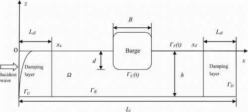
As depicted in Figure , the NWT is enclosed by ΓF(t), ΓU, ΓD, ΓB, and ΓC(t), which represent the time-dependent free-surface, upstream, bottom, downstream, and time-dependent barge-surface boundaries, respectively. The initial condition and boundary conditions for these boundaries are as follows.
2.1.1. Initial condition
In this study, the simulation starts with a calm free surface, hence initially the wave elevation η and velocity potential Φ are set to zero:
(2)
where t is the time.
2.1.2. Boundary condition Γ
The boundary conditions for the NWT are as follows:
(3)
where k is the wave number, ω is the wave frequency, H is the wave height, h is the water depth, ρ is the fluid density, g is the gravitational acceleration, Pa is the atmosphere pressure, vc is the linear velocity of the barge, ωc is the angular velocity of the barge, and r is the position of a point from the barge's center of mass. The unit normal vector of boundaries n = (nx, nz) points out of the domain. Assuming that there is no wave breaking, the wave elevation η can thus be expressed as a function of horizontal location x and time t. Additionally, the constant atmosphere pressure Pa is assumed to be zero in this study.
On the upstream side of the NWT, second-order Stokes regular waves are prescribed to resemble nonlinear incident waves. The normal velocity of the input boundary is given by Equation (3). On the free surface, the fully nonlinear kinematic (Equation (4)) and dynamic (Equation (5)) boundary conditions are applied on the exact free surface z = η(x, t). The exact free surface is tracked by using the mixed Eulerian–Lagrangian (MEL) method. On the flat bottom and downstream sides, the zero-normal-flux boundary condition described in Equation (6) is imposed. On the surface of the body, the non-penetrating flux boundary condition given in Equation (7) applies at each time step. Note that the body surface boundary has to be updated at each time step since the intersection between the free surface and the body surface fluctuate with time.
2.2. Acceleration potential
The instantaneous body pressure around the barge surface can be computed from the unsteady Bernoulli equation:
(8)
By integrating the pressure over the instantaneous wetted body surface, the wave forces Fhydro and Mhydro are then calculated:
(9)
In order to calculate Fhydro and Mhydro, it is necessary to assess the time derivative of the velocity potential or the acceleration potential appearing in Equation (8), Φt ° ∂Φ/∂t, on the body surface. Since Φt also satisfies the Laplace equation, i.e., ∇2Φt = 0, it can be calculated through solving another initial-boundary value problem, whose boundary conditions are given as:
(11)
where
is the angular acceleration of the barge and ac is the linear acceleration of the barge. In Equation (14),
is a term describing the contribution of the velocity field to Φt:
(15)
where κn is the body surface curvature. From Equation (15),
can be computed once the velocity potential Φ is obtained.
The velocity and acceleration potentials are both solved using the DBIEM. The use of this method not only eliminates singularity when conducting the boundary integral but also turns the evaluation of all spatial derivatives analytical for both potentials, which helps to reduce errors caused by numerical differentiation. Furthermore, through realizing the implicit method introduced by Tanizawa (Citation1995) in the present DBIEM framework, the computational efficiency can be much improved (Wang et al., Citation2015), which is introduced in the next section.
2.3. Numerical implementation
2.3.1. Time stepping on the free surface
In the present NWT, the MEL method introduced by Longuet-Higgins and Cokelet (Citation1976) is applied for the time marching of the free surface. In this method, a boundary value problem is solved in the Eulerian frame to obtain the velocity potentials, after which the instantaneous free surface is tracked in the Lagrangian frame using the kinematic and dynamic boundary conditions. By utilizing the material derivative , the fully nonlinear free surface boundary conditions (Equations (4) and (5)) are rewritten as:
(16)
where V represents the velocity of the nodes on the free surface. There are two approaches available when using the MEL method: semi-Lagrangian and material node. When the semi-Lagrangian approach is employed, the node velocity on the free surface is given by:
(18a)
which means that the nodes on the free surface are only allowed to move vertically. On the other hand, in the material node approach the nodes follow the motion of the fluid particles on the free surface; therefore, the node velocity is given by:
(18b)
For the fixed surface-piercing body, the semi-Lagrangian approach is used since the horizontal length of the free surface is unchanged during the simulation, while for the floating body the material-node approach is applied to accommodate the length change of the free surface. The five-point Chebyshev smoothing scheme (Longuet-Higgins & Cokelet, Citation1976) is used to increase numerical stability. The fourth-order predictor–corrector Adams– Bashforth–Moulton scheme (Zhang, Khoo, & Lou, Citation2006) is adopted for the integration of Equations (16) and (17).
2.3.2. Numerical beaches
At the downstream side the implementation of the non-penetrating boundary conditions (Equations (6) and (13)) can cause undesired reflection waves. To mitigate these reflection waves, a numerical beach is applied by imposing a damping layer at the NWT's downstream side (Figure ). The energy of the outgoing waves thus dissipates gradually in the direction in which the waves are advancing. This layer is realized through adding a viscous term to the free surface boundary conditions (Equations (16) and (17)):
(19)
where the tunable damping factor vd(x) is given by:
(21)
In Equation (21), xd is the damping layer's starting abscissa and α is a tuning factor. In this study, α is taken as 1.0 (Contento, Codiglia, & D’Este, Citation2001).
It is also the case that reflected waves can be generated when incident waves reach the barge's weather side, and these need to be eliminated to avoid re-reflection at the NWT's upstream side. Therefore, another damping scheme is employed near the upstream side which only damps out the reflected waves so that the incident waves are not influenced. This damping scheme is similar to the one used for the region near the downstream side, except that the viscous term is different. Details of the scheme used for the region near the upstream side can be found in Tanizawa and Naito (Citation1997).
2.3.3. The desingularized boundary integral equation method (DBIEM)
The boundary value problems related to the velocity and acceleration potentials at each time step are solved using the indirect DBIEM. The potentials are determined through the integration of all Rankine sources along a virtual boundary slightly outside the physical boundaries. Since the Rankine source points are outside the fluid domain and never coincide with boundary points, the DBIEM avoids the singularities often encountered in other methods such as the constant panel method used by Koo and Kim (Citation2004, Citation2007) and the high-order boundary element method used by Bai and Eatock Taylor (Citation2009).
Details of the indirect DBIEM can be found in Zhang et al. (Citation2006) and Wang et al. (Citation2015). In this method, the desingularized distance between boundary points and isolated Rankine source points is determined by the local mesh size, which is measured along the normal direction of the boundaries. As proposed by Cao, Schultz, and Beck (Citation1991), the desingularized distance can be determined by:
(22)
where Dm is the local mesh size and β is the desingularized parameter. As suggested by Cao et al. (Citation1991), when using the DBIEM the numerical results are more accurate when β is chosen from a range between 0.50 and 1.00. Previous work (Wang et al., Citation2015) further found that simulations similar to the present study are insensitive to the desingularized distance when β varies between 0.65 and 1.00; therefore, in this study, β was set to 0.85.
2.3.4. Intersection between the free surface and the body surface
Since in the present fully nonlinear NWT the instantaneous free surface is determined using the free surface boundary conditions (Equations (16) and (17)), the intersections between the free surface and the body surface have to be updated at each time step. With the intersection points updated, the velocity potential at these points can be obtained by interpolation. The double source method proposed by Wang (Citation2005) is adopted to deal with the intersection points in the present indirect DBIEM, where two desingularized point sources are chosen for a control point at the intersection, one inside the body and the other outside the free surface, and their strengths are determined in such a way that both the body and the free surface boundary conditions are satisfied at the control point.
2.4. Validation
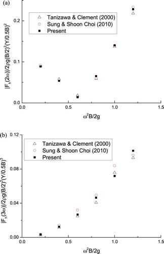
In addition to the validation conducted in the previous study (Wang et al., Citation2015), the present fully nonlinear NWT is further validated through simulating the wave radiation of a sinusoidally heaving wedge. In the wave radiation problem, the motion of the body is prescribed as sinusoidal oscillations. Therefore, the body's linear and angular velocities, i.e., vc and ωc in Equation (7), are known a priori at any instant. Similarly, the body's linear and angular accelerations, i.e., ac and in Equation (14), are also known. The wedge is placed at the upstream side of the NWT. A numerical beach described by Equations (20) and (21) is placed near the downstream side of the NWT in order to damp out the radiated waves. The ratio between its half beam (0.5B) and draft (d) is 0.5B/d = 0.4, and the water depth is h = 3d. In this case, the NWT's total length is set to eight wavelengths, including a two-wavelength damping layer at its downstream side. The wedge is heaving with z(t) = Y sin(ωt), where the heaving amplitude Y = 0.3B. The wave force harmonics are obtained through the fast Fourier transform (FFT) analysis of steady-state force histories in the time domain, including the added mass (A33) and damping coefficients (B33), the second-order harmonics |Fh(2ω)| and the third-order harmonics |Fh(3ω)|. As shown in Figures and , these harmonics are compared with the fully nonlinear simulation results from Tanizawa and Clement (Citation2000) and Sung and Shoon Choi (Citation2010), and good agreement is achieved. The slight differences may stem from the use of different numerical schemes, such as the boundary element method, the size of the computational domain, and damping schemes, etc. In addition, from these results it can be seen that the higher-order wave force harmonics are sensitive to the dimensionless frequency (Figure ). The magnitude of the second-order harmonic |Fh(2ω)| reaches its minimum near the frequency ω2B/2 g = 0.6, while the third-order harmonic |Fh(3ω)| increases monotonically with the frequency.
Figure 2. Coefficients of a surface-piercing wedge with a forced motion amplitude of Y = 0.3B: (a) added mass coefficients and (b) damping coefficients.
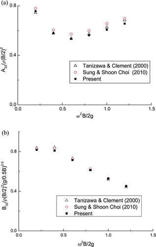
Figure 3. High-order harmonics of the heave force of a surface-piercing wedge with a forced motion amplitude of Y = 0.3B: (a) second-order harmonics and (b) third-order harmonics.
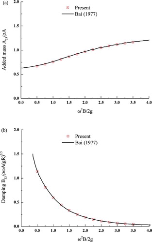
To validate the present NWT's capability in simulating wave–body interactions in water of finite depth, another wave-radiation problem is simulated in which a circular cylinder with a radius R and draft d ( = R) sinusoidally heaves with z(t) = −Y sin(ωt), where the heaving amplitude Y = 0.01R in water of depth h = 1.5d. Except for the body geometry and water depth, the NWT settings are almost the same as in the previous validation case. As shown in Figure , the added mass (A33) and damping coefficients (B33) that vary with frequency are compared with the numerical results in K. Bai (Citation1977), and a very good agreement is achieved.
Figure 4. Coefficients of a semi-submerged circular cylinder with a forced motion amplitude of Y = 0.01R: (a) added mass coefficients and (b) damping coefficients.
3. Results and discussion
3.1. Wave interaction with a fixed surface-piercing body in deep water
In this section, the fixed surface-piercing barge is introduced into the NWT and the wave diffraction around the barge in deep water is investigated to serve as a benchmark. Since the barge is fixed, the barge's linear and angular velocities, i.e., vc and ωc in Equation (7), and the barge's linear and angular accelerations, i.e., ac and in Equation (14), are zero. The water depth is chosen as kh = 2π, the same value as used in Tanizawa and Minami (Citation1998) and Koo and Kim (Citation2007). Other values are set as follows: the width of the barge B = 0.5 m, the draft d = 0.25 m, and the radius of the round corner r = 0.064 m. The size of the barge in the y-direction is taken to be L = 1 m for this 2D simulation. The NWT's total length is set to six wavelengths, in which one wavelength is taken by the downstream damping layer and another by the upstream damping layer. Two different wave heights (H = 0.01 m and H = 0.07 m) are used for incident waves with the non-dimensional frequency ξ = ω2B/2g varying from 0.5 to 2.0. Although not presented in this paper, a convergence test was conducted and the following parameters were found to be most appropriate for the current simulations: a time step size of T/125 and a grid size of 60 nodes per wavelength on the free surface and 100 nodes on the body surface.
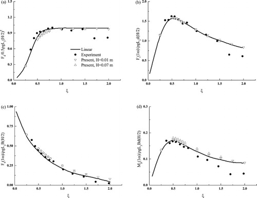
The wave-exciting forces including the drift force, surge force, heave force and pitch moment on the fixed barge are calculated and presented in Figure . The results are generally in good agreement with the experimental data from Nojiri and Murayama (Citation1975) except at high frequencies. For waves with a small amplitude H = 0.01 m, the simulation results are close to the linear-theory predictions from Maruo (Citation1960) throughout the investigated frequency range. For waves with a large amplitude H = 0.07 m, the results from the present fully nonlinear simulation are also close to the linear-theory predictions at frequencies no greater than ξ = 1.50. At frequencies greater than ξ = 1.50, however, the simulation becomes unstable because the wave steepness (ka = 0.21) is so high that the incident wave tends to break – a phenomenon that the present NWT cannot handle. Similar observations are also reported by Tanizawa and Minami (Citation1998); in their simulation, the upper limit of frequency for stable simulation is ξ = 1.75. For this reason, the simulation results for H = 0.07 m waves are not presented at frequencies ξ > 1.50. The significant discrepancy between the experimental data and the H = 0.07 m simulation results and the linear-theory predictions is believed to be attributed to the nonlinearity in the experiments.
Figure 5. Comparison of normalized wave-exciting forces in deep water: (a) drift force, (b) surge force, (c) heave force, and (d) pitch moment.
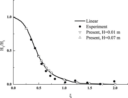
The wave reflection coefficient (HR/HI) and transmission coefficient (HT/HI) were also calculated (Figures and ). Three wave gauges were placed at x = 1.9 λ, 2.0 λ and 4.0 λ, where the first two gauges are in front of the fixed body and the third one is behind it. The reflected waves are separated from the incident wave by the two-point method developed by Goda and Suzuki (Citation1976). Overall, the simulation results agree with both the linear-theory predictions and the experimental data.
Figure 6. Comparison of the wave reflection coefficient.
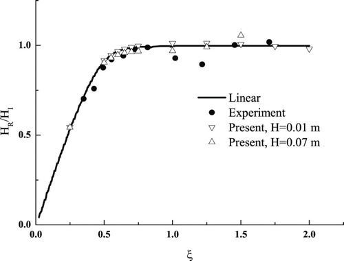
Figure 7. Comparison of the wave transmission coefficient.
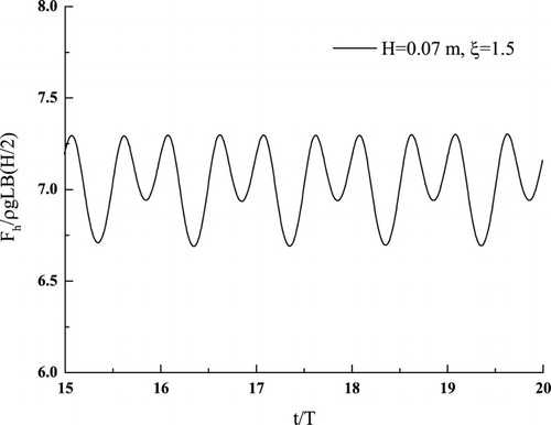
Higher-order harmonic components of the hydrodynamic forces experienced by the fixed barge were also obtained. As an example, Figure shows the first three harmonic components of the heave force under the H = 0.07 m waves. At low frequencies, the first-order harmonic components are much larger than the second- and third-order components. As the frequency increases, the second-order components become significant and even greater than the first-order components, whereas the third-order components still remain very small. As an example, the time history of the steady-state heave force at ξ = 1.5 is plotted in Figure , which clearly shows the dominance of the second-order harmonic component. These trends have also been confirmed by other researchers using either numerical methods (Koo & Kim, Citation2007) or the second-order perturbation theory (Kim, Citation1993; Kim & Yue, Citation1989).
Figure 8. Comparison of normalized heave force components for H = 0.07 m.
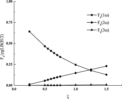
Figure 9. Time history of the normalized heave force with incident waves of H = 0.07 m and ξ = 1.5.
3.2. Wave interaction with a fixed surface-piercing body in water of finite depth
With the established NWT, a parametric study was conducted on waves interacting with the fixed barge in water of finite depth. There are eight parameters for this wave–body interaction problem: fluid density ρ, gravity g, water depth h, wave height H, wavelength λ, wave frequency ω, barge width B, and draft d. Of these, seven are independent since the wave frequency can be determined by the wavelength and water depth from the wave dispersion relationship. By applying the Buckingham Pi theorem, four independent non-dimensional parameters – i.e., water depth, wave steepness, wave frequency, and beam–draft ratio – are identified to govern the present wave–body interaction problem:
(23)
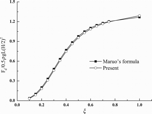
For a simple validation, the drift forces evaluated by the present NWT at various frequencies and kh = 0.5π, ka = 0.01, and = 2.0 are compared with the prediction from the modified Maruo's formula (Faltinsen, Citation1990). As shown in Figure , the results calculated from the two methods are close to each other both in value and trend. From this result it can also be seen that the maximum value of the normalized drift force exceeds unity, confirming the effect of the finite water depth.
Figure 10. Comparison of normalized drift forces calculated by the Maruo's formula (Faltinsen, Citation1990) and by the direct pressure integration method.
In the present parametric study, the following baseline parameters are set: the wave steepness ka = 0.125, the wave frequency ξ = 0.75, and the beam–draft ratio = 2.0. The water depth kh ranges from 0.5π to 2π, covering the range of finite to deep water depths. The ranges for the other three parameters are chosen as 0.05 ≤ ka ≤ 0.2, 0.25 ≤ ξ ≤ 1.25, and 1.43 ≤
≤ 3. Figures to show the variation of the normalized wave-exciting forces against the four parameters, in which the water depth appears as one horizontal axis and one of the other three parameters appears as the other horizontal axis. Note that for the surge force Fs, heave force Fh, and pitch moment Mr, only the first-order harmonics are presented. From these figures it can be seen that all four hydrodynamic forces increase as the water depth reduces. Among them, the largest increment of 123% occurs in the heave force at ξ = 1.25 (Figure (c)).
Figure 11. Effect of the water depth and incident wave steepness on the wave-exciting forces: (a) drift force, (b) surge force, (c) heave force, and (d) pitch moment.
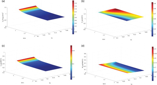
Figure 12. Effect of the water depth and incident wave frequency on the wave-exciting forces: (a) drift force, (b) surge force, (c) heave force, and (d) pitch moment.
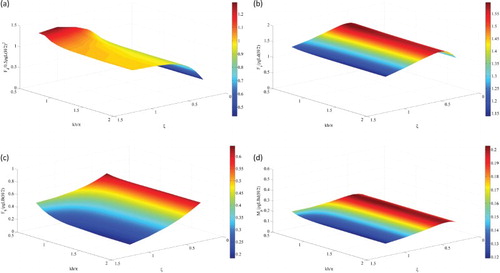
Figure 13. Effect of the water depth and beam–draft ratio on the wave-exciting forces: (a) drift force, (b) surge force, (c) heave force, and (d) pitch moment.
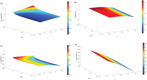
From Figure , it can be seen that at a given water depth, no matter whether it is finite or deep, the drift and heave forces remain almost unchanged, the surge force decreases a little, and the pitch moment increases as the wave steepness ka increases, indicating that of the four forces, the pitch moment is more sensitive to the wave steepness.
The trends of the wave-exciting forces against the frequency ξ are a little complicated. As shown in Figure , as ξ increases, single peaks appear at ξ = 0.5 in the surge force and pitch moment, a plateau occurs at about ξ > 1.0 in the drift force, and a monotonic decrease occurs in the heave force. Although showing similar variation trends against ξ at various water depths, the drift force in water of finite depth (kh = 0.5π) is quite different from that of deep water (kh = 2π). The same finding also applies to the heave force and pitch moment.
The beam–draft ratio also affects the wave-exciting forces. It can be seen from Figure that as
increases, the surge force, heave force, and pitch moment also increase whereas the drift force decreases. The increase of the pitch moment is dramatic – about 33 times at kh = 2π – because an increase in the beam results in an increase of the arm for the positive pitch moment, while a decrease in the draft results in a decrease of the forces that produce negative moments.
High-order harmonics of the wave-exciting forces were also obtained. Figures to show the variations of the first three harmonics of the wave-exciting forces against the wave height kh, wave steepness ka, wave frequency ξ, and beam–draft ratio , respectively. In general, the magnitudes of the first-order harmonics are the largest pf the three, and the magnitudes of the third-order harmonics are the smallest. As shown in Figures (a) to (a), the second- and third-order surge force components are very close to each other, both of which are at least one order less than the first-order components except at low wave frequencies, which result in the second-order components increasing significantly. This indicates that the nonlinear effect on the surge force can be neglected in most cases. However, the same statement does not apply to the heave force and pitch moment. For these two forces, the second-order harmonics can be in the same order of the first-order harmonics and significantly higher than the third-order harmonics in certain circumstances. At
= 1.43 (Figure (c)), they are even higher than their first-order counterpart.
Figure 14. Effect of the water depth on the first three harmonics of the wave-exciting forces: (a) surge force, (b) heave force, and (c) pitch moment.
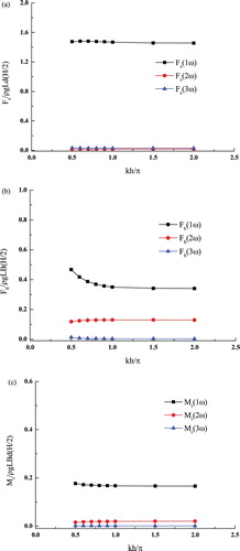
Figure 15. Effect of the incident wave steepness on the first three harmonics of the wave-exciting forces: (a) surge force, (b) heave force, and (c) pitch moment.
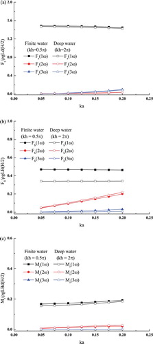
Figure 16. Effect of the incident wave frequency on the first three harmonics of the wave-exciting forces: (a) surge force, (b) heave force, and (c) pitch moment.
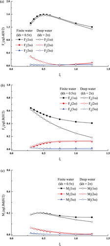
Figure 17. Effect of the beam–draft ratio on the first three harmonics of the wave-exciting forces: (a) surge force, (b) heave force, and (c) pitch moment.
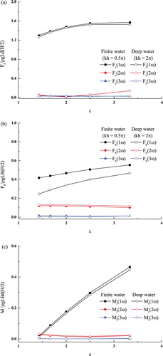
The variations of the high-order harmonics in water of finite and deep depth, i.e., kh = 0.5π to 2π, are also presented in Figures to . It can be seen that although the first-order harmonics in water of finite depth are larger than those in deep water, the second-order harmonics for the finite water depth are generally smaller, especially for the heave force and pitch moment, while the third-order harmonics are again larger.
3.3. Wave interaction with a floating surface-piercing body in water of finite depth
In this section, the barge was allowed to float and oscillate in all three degrees of freedom (DOFs) on the free surface, and its interaction with incident waves in water of finite depth was investigated. Its mass is mc = 125 kg and its moment of inertia is Ic = 4.05 kg·cm2 about the center of mass, which is 0.115 m below the free surface. This floating barge was connected horizontally with a spring (whose stiffness was 197.58 N/m) and a damper (with a damping coefficient of 19.8 N·s/m), the same as the settings in Nojiri and Murayama (Citation1975) and Koo and Kim (Citation2004) except that the water depth varies in the present study. With the focus placed on the effects of the water depth on the wave forces acting on the barge and the barge's response to these effects, the following parameters were chosen: the wave steepness ka = 0.125, the wave frequency ξ = 1, and the beam–draft ratio = 2.0. The water depth kh ranged from 0.5π to 2π, covering both finite and deep water depths.
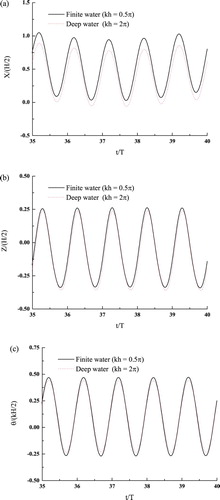
In Figure , the time histories of the steady-state wave forces are plotted for both a finite depth kh = 0.5π and a deep depth kh = 2π. In addition, the resulting motions of the floating barge are shown in Figure . As can be seen from Figures and , the water depth shows its significance on the wave forces and the motions of the floating barge. This is obviously seen from the surge motion shown in Figure (a).
Figure 18. Wave forces acting on the floating barge over time: (a) surge force, (b) heave force, and (c) pitch moment.
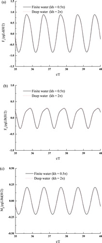
Figure 19. Motions of the floating barge over time: (a) surge force, (b) heave force, and (c) pitch moment.
By performing FFT on the time histories of the wave forces, the first three harmonics of the wave forces acting on the floating barge varying according to water depth were calculated and are presented in Figure . It can be seen that the trends are similar to those found with the fixed barge. The magnitudes of the first-order harmonics are the largest among the three and generally decrease as the water depth increases. The second-order harmonics however slightly increase as the water depth increases, especially for the heave force and the pitch moment. In addition, compared to those for the surge force and pitch moment, the second-order harmonics of the heave force are much more significant, which are about 25% of the first-order harmonics in the investigated water depth range.
Figure 20. Effect of the water depth on the first three harmonics of the wave forces acting on the floating barge: (a) surge force, (b) heave force, and (c) pitch moment.
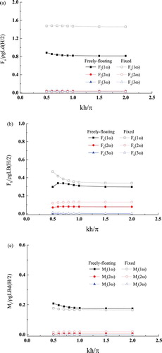
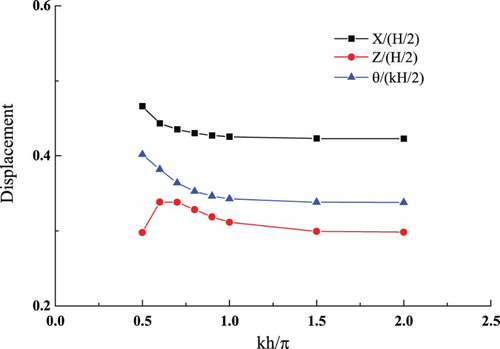
When the surface-piercing barge is allowed to move under the excitation of both hydrodynamic and spring forces, in the first-order harmonics the surge force drops by about 40% on average and the heave force drops by about 15%, while the pitch moment increases by about 10%. Furthermore, a peak appears at kh = 0.6π for the first-order harmonics of the heave force. This is different from the heave force curve of the fixed barge (Figure (b)), which monotonically decreases with the water depth. The variation of the heave force for the free-floating barge may be attributed to the wave radiation since the free-floating barge itself can produce waves and thus influence the pressure around the barge surface. In the frequency domain, Bai (Citation1977) has also shown the dependence of the added-mass and damping coefficients on the water depth for a heaving two-dimensional rectangular cylinder. Moreover, both Clauss et al. (Citation2009) and Kim and Kim (Citation2012) have shown the dependency of a floating body's hydrodynamic coefficients on the water depth. In this study, apart from the wave-exciting force, the heave force which results from wave radiation also varies according to the water depth. With the combination of the wave-exciting force and wave-radiation force, the resulting heave force exhibits a peak at kh = 0.6π (Figure ). As a result, the heave motion of the floating barge system also shows a peak at kh = 0.6π (Figure ). Compared with the heave motion with deep water (kh = 2π), it shows about a 13% increase with the finite depth kh = 0.6π. This significant difference indicates the great impact of the water depth on the motions experienced by the floating barge.
Figure 21. Effect of the water depth on the displacement of the free-floating barge.
4. Conclusions
The interaction between waves and surface-piercing bodies in water of finite depth was simulated using a potential-theory-based, two-dimensional, fully nonlinear NWT. With this numerical model, a parametric study was conducted to investigate the effects of the water depth kh, wave steepness ka, wave frequency ξ, and beam–draft ratio on the wave-exciting forces acting on a fixed surface-piercing barge. The main findings are as follows:
A reduction in the water depth kh from deep to finite enhances all the wave-exciting forces that were investigated.
An increase in the wave steepness ka results in increased pitch moment, a slightly decreased surge force, and almost unchanged drift and heave forces.
As the wave frequency ξ increases, single peaks appear at ξ = 0.5 for the surge force and pitch moment, a plateau appears at about ξ > 1.0 for the drift force, and a monotonic decrease happens to the heave force.
An increase in the beam–draft ratio
causes an increase in the surge force, heave force, and pitch moment, and a decrease in the drift force; of these, the increase in the pitch moment is massive.
The second- and third-order harmonics of the surge force can generally be neglected, whereas the second-order harmonics of the heave force and pitch moment are significant.
Although the first-order harmonics in water of finite depth are larger than those in deep water, the second-order harmonics are generally smaller, especially for the heave force and pitch moment.
The barge was then allowed to move and the influence of the water depth on its wave-exciting forces was investigated. It was found that with the body motion involved, the surge force and heave force reduce in the first-order harmonics, while the pitch moment increases. In addition, a peak appears at kh = 0.6π for the first-order harmonics of the heave force as well as for the heave displacement, indicating the great impact of the water depth on the motions experienced by the floating barge.
Through this research, a better understanding of the effects of water depth on wave–body interactions has been achieved. However, the present NWT shows some limitations and requires further development. For example, numerical inability is observed when the water depth is less than kh = 0.5π. In addition, the present NWT is only two-dimensional. In the near future, the same problem will be reinvestigated using a three-dimensional, fully nonlinear NWT to gain more physical insights.
Acknowledgements
The first author of this paper, Dr. Lixian Wang, would like to acknowledge the financial support from Nanyang Technological University for his PhD study.
Disclosure statement
No potential conflict of interest was reported by the authors.
ORCiD
Hui Tang http://orcid.org/0000-0002-6774-507X
References
- Anderson, P. (1979). Ship motions and sea loads in restricted water depth. Ocean Engineering, 6(6), 557–569. doi: 10.1016/0029-8018(79)90007-6
- Bai, K. (1977). The added mass of two-dimensional cylinders heaving in water of finite depth. Journal of Fluid Mechanics, 81(1), 85–105. doi: 10.1017/S002211207700192X
- Bai, W., & Eatock Taylor, R. (2009). Fully nonlinear simulation of wave interaction with fixed and floating flared structures. Ocean Engineering, 36(3–4), 223–236. doi: 10.1016/j.oceaneng.2008.11.003
- Boo, S. Y. (2002). Linear and nonlinear irregular waves and forces in a numerical wave tank. Ocean Engineering, 29(5), 475–493. doi: 10.1016/S0029-8018(01)00055-5
- Cao, Y., Schultz, W. W., & Beck, R. F. (1991). Three-dimensional desingularized boundary integral methods for potential problems. International Journal for Numerical Methods in Fluids, 12(8), 785–803. doi: 10.1002/fld.1650120807
- Chaplin, J. R. (1984). Nonlinear forces on a horizontal cylinder beneath waves. Journal of Fluid Mechanics, 147, 449–464. doi: 10.1017/S0022112084002160
- Clauss, G., Stempinski, F., Dudek, M., & Klein, M. (2009). Ocean Engineering, 36(17–18), 1396–1403. doi: 10.1016/j.oceaneng.2009.08.020
- Contento, G., Codiglia, R., & D’Este, F. (2001). Nonlinear effects in 2D transient nonbreaking waves in a closed flume. Applied Ocean Research, 23(1), 3–13. doi: 10.1016/S0141-1187(01)00002-5
- Faltinsen, O. (1990). Sea loads on ships and offshore structures. Cambrige, UK: Cambridge University Press.
- Folley, M., Whittaker, T. J. T., & Henry, A. (2007). The effect of water depth on the performance of a small surging wave energy converter. Ocean Engineering, 34(8–9), 1265–1274. doi: 10.1016/j.oceaneng.2006.05.015
- Goda, Y., & Suzuki, Y. (1976). Estimation of incident and reflected waves in random wave experiments. Proceedings of 15th Conference on Coastal Engineering (pp. 828–845). ASCE, Reston, VA, USA.
- Isaacson, M., & Cheung, K. F. (1991). Second order wave diffraction around two-dimensional bodies by time-domain method. Applied Ocean Research, 13(4), 175–186. doi: 10.1016/S0141-1187(05)80073-2
- Jagadeesh, P., & Murali, K. (2010). Rans predictions of free surface effects on axisymmetric underwater body. Engineering Applications of Computational Fluid Mechanics, 4(2), 301–313. doi: 10.1080/19942060.2010.11015318
- Jonkman, J. M. (2007). Dynamics modelling and loads analysis of an offshore floating wind turbine. Technical Report NREL/TP-500-41958.
- Kim, M.-H. (1993). Second-harmonic vertical wave loads on arrays of deep-draft circular cylinders in monochromatic uni- and multi-directional waves. Applied Ocean Research, 15(5), 245–262. doi: 10.1016/0141-1187(93)90014-O
- Kim, M.-H., & Yue, D. K. P. (1989). The complete second-order diffraction solution for an axisymmetric body Part 1. Monochromatic incident waves. Journal of Fluid Mechanics, 200, 235–264. doi: 10.1017/S0022112089000649
- Kim, T., & Kim, Y. (2012). Numerical study on floating body motions in finite depth. International Journal of Ocean System Engineering, 2(3), 176–184. doi: 10.5574/IJOSE.2012.2.3.176
- Koo, W. C., & Kim, M. H. (2004). Freely floating-body simulation by a 2D fully nonlinear numerical wave tank. Ocean Engineering, 31(16), 2011–2046. doi: 10.1016/j.oceaneng.2004.05.003
- Koo, W. C., & Kim, M. H. (2007). Fully nonlinear wave-body interactions with surface-piercing bodies. Ocean Engineering, 34(7), 1000–1012. doi: 10.1016/j.oceaneng.2006.04.009
- Liu, C. F., Teng, B., Gou, Y., & Sun, L. (2011). A 3D time-domain method for predicting the wave-induced forces and motions a floating body. Ocean Engineering, 38(17–18), 2142–2150. doi: 10.1016/j.oceaneng.2011.09.034
- Liu, C., Huang, Z., & Tan, S. K. (2009). Nonlinear scattering of non-breaking waves by a submerged horizontal plate: Experiments and simulations. Ocean Engineering, 36(17–18), 1332–1345. doi: 10.1016/j.oceaneng.2009.09.001
- Li, Y., & Lin, M. (2010). Wave-body interactions for a surface-piercing body in water of finite depth. Journal of Hydrodynamics, Ser. B, 22(6), 745–752. doi: 10.1016/S1001-6058(09)60112-8
- Li, Y. & Lin, M. (2012). Regular and irregular wave impacts on floating body. Ocean Engineering, 42, 93–101. doi: 10.1016/j.oceaneng.2012.01.019
- Longuet-Higgins, M. S., & Cokelet, E. D. (1976). The deformation of steep surface waves on water: I. a numerical method of computation. Proceedings of the Royal Society A: Mathematical, Physical and Engineering Sciences, 350, 1–26. doi: 10.1098/rspa.1976.0092
- Maruo, H. (1960). On the increase of the resistance of a ship in rough seas. Journal of Zosen Kiokai, 108, 5–13. doi: 10.2534/jjasnaoe1952.1960.108_5
- Newman, J. (1977). Marine hydrodynamics. Cambridge, MA: The MIT Press.
- Nojiri, N., & Murayama, K. (1975). A study on the drifting force on two-dimensional floating body in regular waves. Transaction of the West-Japan Society Naval Architects, 51, 131–152.
- Perunovic, J. V., & Jenson, J. J. (2003). Wave loads on ships sailing in restricted water depth. Marine Structures, 16(6), 469–485. doi: 10.1016/j.marstruc.2003.08.001
- Sung, H. G., & Shoon Choi, H. (2010). Implicit formulation with the boundary element method for nonlinear radiation of water waves. Engineering Analysis with Boundary Elements, 34(5), 511–529. doi: 10.1016/j.enganabound.2009.11.005
- Tanizawa, K. (1995). A nonlinear simulation method of 3-D body motions in waves formulation with the acceleration potential. Abstract for the 10th International Worshop on Water Waves and Floating Bodies.
- Tanizawa, K., & Clement, A. H. (2000). Report of the 2nd workshop of ISOPE numerical wave tank group: benchmark test cases of radiation problem. Proceedings of the 6th International Offshore and Polar Engineering Conference.
- Tanizawa, K., & Minami, M. (1998). On the accuracy of NWT for radiation and diffraction problem. The 6th Symposium on Nonlinear and Free-Surface Flow.
- Tanizawa, K., & Naito, S. (1997). A study on parametric roll motions by fully nonlinear numerical wave tank. Proceedings of the 7th International Offshore and Polar Engineering Conference, Honolulu, Hawaii, USA.
- Tuck, E. O. (1970). Ship motions in shallow water. Journal of Ship Research, 14(4), 317–328.
- Wang, L., Tang, H., & Wu, Y. (2015). Simulation of wave–body interaction: A desingularized method coupled with acceleration potential. Journal of Fluids and Structures, 52, 37–48. doi: 10.1016/j.jfluidstructs.2014.08.009
- Wang, Q. X. (2005). Unstructured MEL modelling of nonlinear unsteady ship waves. Journal of Computational Physics, 210(1), 368–385. doi: 10.1016/j.jcp.2005.04.012
- Wu, G. X., & Eatock Taylor, R. (2003). The coupled finite element and boundary element analysis of nonlinear interactions between waves and bodies. Ocean Engineering, 30(3), 387–400. doi: 10.1016/S0029-8018(02)00037-9
- Zhang, X., Khoo, B., & Lou, J. (2006). Wave propagation in a fully nonlinear numerical wave tank: A desingularized method. Ocean Engineering, 33(17–18), 2310–2331. doi: 10.1016/j.oceaneng.2005.11.002