
ABSTRACT
The channel fracturing technique has been proven to provide much higher conductive fracture networks by placing discontinuously proppant inside fracture packs. Despite the great success of this new fracturing technique, there is still a lack of models and methods to characterize non-uniform placement of fracture proppant and heterogeneous permeability distribution within stimulated-reservoir-volume (SRV). In this article, a dual-porosity model is coupled with the tri-linear flow model to quantify the production performance of channel fractured horizontal wells. As a consequence of channel fracturing, the non-uniform distribution of fracture networks, and the heterogeneities of both matrix/fracture porosity and permeability are characterized using fractal theory. By implementing the Bessel Function and Laplace transform techniques, analytical solutions are derived by integrating fluid flow across primary hydraulic fractures, SRV and unstimulated reservoir matrices. Through quantitative comparisons of well bottom-hole pressure history, a synthetic fine-grid numerical simulation example is implemented to verify the accuracy of analytical solutions. Sensitivity analysis of fractal dimension, fractal connectivity-index and primary fracture conductivity is carried out to quantify the temporal and spatial consequences of channel fracturing on both reservoir/facture heterogeneity and well productivity throughout well life.
1. Introduction
In recent years, shale oil and gas have greatly contributed to the US energy portfolio and are expected to be the main source of energy within the next 20 years. The majority of commercial production in shale play requires intensive fracturing along with long horizontal well drilling (Abdulal, Samandarli, & Wattenbarger, Citation2011; Britt & Smith, Citation2009; Wang & Wu, Citation2013). As a widespread and effective approach, multi-stage fractured horizontal wells have made oil and gas production more efficient and economical in shale plays. In addition, in view of incidences of natural fractures, hydraulic fracturing can not only create high-conductive and long primary fractures but also reactivate sealed natural fractures to generate intensively complex fracture networks around wells (Clarkson, Citation2013; Mayerhofer et al., Citation2010; Wang et al., Citation2015; Wang, Su, Zhang, Sheng, & Ren, Citation2015; Yuan et al., Citation2015).
The primary goal of hydraulic fracturing is to create highly conductive flow paths for the reservoir fluids coming out. Therefore, it is necessary to create enough high conductivity for fractures to guarantee excellent performance from well production (Britt & Bennett, Citation1985; Economides & Nolte, Citation2000). Inside hydraulic fracturing, the proppant pack serves as a mechanical support to open hydraulic fractures, which form a highly conductive porous medium for fluid flow. Proppant has evolved from nutshells and wood chips, to natural sands, and to strong ceramic particles. Fracturing fluid includes gelled oils, water-based fluids, and viscoelastic surfactant-based solutions (Denney, Citation2010; Medvedev, Kraemer, Pena, & Panga, Citation2013; Stephens et al., Citation2007; Vincent, Citation2009). The majority of existing published works have focused on enhancing the total flow rates inside hydraulic fractures; however, the optimization of fracture proppant placement is still in progress.
The channel fracturing technique is a novel approach that replaces the homogenous placement of proppants inside hydraulic fractures using the heterogeneous distribution of proppants (Gillard et al., Citation2010). The objective of channel fracturing is to enhance fracture conductivity by creating a more stable network with open channels. The heterogeneous conglomerations of injected proppant can support the openness of hydraulic fractures for the transport of reservoir fluids with much smaller flow resistance. The conglomerates of degradable fibrous materials are introduced to prevent the dispersion of the injected proppant. The series of open channels inside hydraulic fractures are reached using an integrated approach to optimize the pumping schedule and perforation strategy technology. As a result of heterogeneous distribution of fracturing proppants, the channel-fracturing technique could provide fracture conductivity that is several folds larger with proppant-free conduit fractures than that of conventional continuous placement of proppant (Yudin et al., Citation2012). In the past three years channel fracturing treatments have been applied in over 1000 wells in the Loma La Lata field, Argentina (Gillard et al., Citation2010), Vaca Muerra Shale, Neuquen (Ejofodomi, Cavazzoli, Morris, & Prioul, Citation2014), the Taylakovskoe Oil Field Stud Horse Buttle (Johnson et al., Citation2011), Abu Roach, Egypt and Eagle Ford Shale (Inyang, Nguyen, & Cortez, Citation2014). Channel fracturing has been proven to both enhance production and be more economical (Altman et al., Citation2012). However, despite the great success of channel fracturing application in certain types of reservoir, the unique features of channel fracturing, such as the highly heterogeneous distribution of open channels and non-uniform fracture intensity, are still unknown, which leads to difficulties for fracture characterization and productivity analysis.
Recently, a series of analytical, semi-analytical and numerical methods have been introduced to model the fluid flow around multi-stage fractured horizontal wells (MFHW) (Huang, Zhang, & Pei, Citation2013; Selimefendigil, Citation2013). Ozkan, Brown, Raghavan, and Kazemi (Citation2009) and Ozkan, Raghavan, and Apaydin (Citation2010) first introduced a tri-linear flow model to handle key characteristics of multiple fractures along horizontal wells. Stalgorova and Mattar (Citation2012) extended the tri-linear flow model to a five-region flow model in order to take the finite size of stimulated-reservoir-volume (SRV) (its width is less than fracture spacing) into consideration. Yuan et al. (Citation2015) presented a septa-linear flow model to consider the non-uniform distribution of fracture networks within SRV. In addition, dual-porosity, dual-permeability models are used to describe the different contributions of fractures and matrices within SRV (Altman et al., Citation2012; Wang, Su, Sheng, Cossio, & Shang, Citation2015; Wang, Zhou, & Luo, Citation2010; Zhao, Zhang, Luo, & Zhang, Citation2014). The reservoir matrix is usually regarded as the storage space, and the high-conductive fractures perform the role of the primary flow paths for reservoir fluids. Fractal theory is also implemented to describe the heterogeneity of fracture networks around fractured horizontal wells (Costantini, Falcone, Hewitt, & Alimonti, Citation2008; Guo, Zhang, Zhang, Qing, & Liu, Citation2012). Wang, Shahvali, and Su (Citation2015) incorporated the tri-linear flow model with fractal theory to study the impacts of fracture heterogeneity on well productivity.
This work introduces a quantitative characterization of fracture networks with open channels after channel fracturing. Fractal theory is combined with the tri-linear flow model in a dual-porosity matrix-fracture system to present the production of multistage fractured horizontal wells. The non-uniform distribution of fracture permeability and porosity are also characterized using the fractal permeability–porosity relationship. Our analytical solutions are verified using numerical simulations.
2. Fracture conductivity with open channels
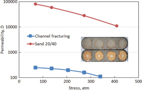
The objective of the channel fracturing technique is to introduce a heterogeneous fracture structure with open channels inside fractures instead of the conventional homogenous distribution of proppant pack to enhance the flow capacity of reservoir fluids. As shown in Figure , after the dispersion, mixing and settling process of fracturing proppant pulse, the open channels are formed inside the fractures, with the help of the fracturing fluid viscosity and fiber concentration properly tailored inside the fractures. In-house laboratory experiments were conducted to estimate the enhancement of fracture conductivity with channel fracturing (Medvedev et al., Citation2013). The results indicated that the enhancement of fracture conductivity by a non-uniform proppant cluster is several orders of magnitude larger than that of a 20/40-mesh sand proppant pack with even distribution (Figure ).
Figure 1. Schematic diagram of conventional fracturing and channel fracturing technology, modified from Gillard et al. (Citation2010).
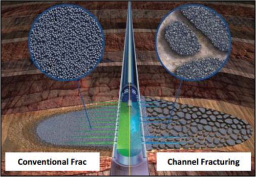
Figure 2. Enhanced conductivity with non-uniform proppant clusters, modified from Medvedev et al. (Citation2013).
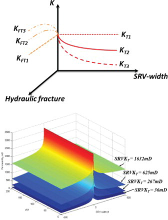
In addition, as the hydraulic fracture propagates into the deep reservoir, the ‘stimulation intensity’ gradually attenuates, which leads to a decrease of permeability within SRV. Hence, in this article, the concept of threshold permeability (TP) is proposed to represent permeability at the outer boundary of stimulated reservoir volume (which is still much higher than matrix permeability). In addition, three scenarios with different threshold fracture conductivity – KFT1, KFT2, KFT3 – are compared. Variations in the fracture conductivity of the proppant pack and permeability along the SRV are shown in Figure . As the fracture networks propagate within the region of SRV, the average permeability decreases gradually and reaches KT3 at the boundary of SRV, very close to the initial matrix permeability. This means that less fracture proppant is pumped into the induced fracture network remote from the primary fracture. In Figure , KT1 represents the case with constant fracture permeability with uniform fracture proppant placement throughout SRV, which is described by the conventional dual-continuum model. The KT2 curve represents another scenario with the enhancement of fracturing intensity by the formation of open channels; as a result, the values of threshold permeability become larger than the permeability of matrix reservoirs. As for the permeability of primary fractures, the heterogeneity of fracture proppant placement leads to the non-uniform distribution of permeability inside the fractures. In addition, due to the conglomeration of proppant at the end of fractures to support the hydraulic fractures as openly as possible, the permeability of hydraulic fractures shows an upward trend as the primary fracture propagates.
Figure 3. Concept of threshold permeability (stimulated reservoir volume threshold permeability, right).
The natural microfractures could be re-activated by the energy of hydraulic fracturing, which would connect the induced primary fracture as networks. However, due to the attenuation of fracturing energy in deep reservoirs, there is less natural fracture to be activated far away from wells. Wang, Shahvali, and Su (Citation2015) introduced the concepts of fractal permeability and fractal porosity for the dual-porosity system of SRV. This article extends the fractal theory to demonstrate the non-uniform distribution of proppant pack inside both primary fractures and SRV caused by the channel fracturing technique, as shown in Equations (1–6):
(1)
(2)
(3)
(4)
(5)
(6)
where di denotes the fractal dimension, representing the dimension of the fractal fracture network embedded in the Euclidean matrix (i = f), fractal matrix porous media (i = m) and proppant pack (i = F);
is half the width of the hydraulic fracture;
,
is the connectivity index characterizing the diffusion process or diffusivity capacity – this parameter is related to the spectral exponent;
,
,
,
are the properties at the boundary shared by the SRV;
and
are the properties at the boundary shared by the primary fracture;
is half the length of the hydraulic fracture.
3. Mathematical model
3.1 Physical assumptions
The finite-conductive primary fracture is located centrally in a closed rectangular system, with a half-length of xf, with bf, and penetrates the entire formation vertically. The spacing among neighboring fractures is 2ye, and no flow boundary exists in the middle of them. The lateral boundaries perpendicular to the primary fracture plane are assumed at the distance of xe from the center of fractures. The number of fractures is N = Lh/2ye, where Lh is length of SRV. Therefore, the drainage area of a single fracture is equal to 1/N of the total drainage area of MFHW with N identical transverse hydraulic fractures, as shown in Figure . Therefore, the pressure-transient flow model of a horizontal well can be describled as the sum of a single fracture with a constant production rate equal to qf = q/N. Some basic assumptions commonly used for MFHW are applied, as follows:
Local thermal equilibrium, and single phase oil or gas flow are applied.
No flow interaction is considered between matrix systems and wellbore.
The interference among a transverse fracture is modeled using no-flow boundaries.
Figure 4. Arrangement of SRVs for fractured horizontal well with N identical transverse hydraulic fractures.
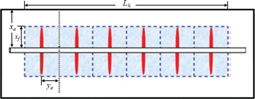
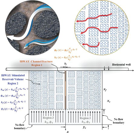
Figure presents the scheme of the tri-linear flow model with fractal permeability and porosity for a HiWAY-Channel Fractured horizontal well. It includes linear flow in the primary fracture (region 1), the SRV (region 2) and the outer-reservoir region (region 3). The fluid flow in each region is represented by the diffusivity equation with two boundary conditions. In addition, Euclidean diffusivity equations in each region are replaced by the fractal diffusivity model incorporated with fractal permeability and porosity relationships. In Figures and the subscripts m and f denote the fractal matrix and fractal fracture, respectively, within the dual-porosity SRV region.
Figure 5. Schematic of HiWAY-Channel Fracturing fractal flow physical model.
3.2 Model descriptions
Dimensionless variables are defined as follows:
(7)
(8)
(9)
(10)
(11)
The diffusivity equations of incompressible fluid flow within different regions are derived as shown below:
Linear flow in outer unstimulated reservoir
The outer unstimulated reservoir is regarded as a single-continuum matrix medium. The diffusivity equation with dimensionless variables to describe the fluid linear-flow along x direction is,
(12)
Using Laplace transform, the equation could be expressed as,
(13)
where
. Analytical solutions of Equation (12) under Laplace space can be obtained as
(14)
Inner-boundary condition: Outer-boundary condition:
Linear flow within dual-porosity SRV with fractal theory
With the assumption of a pseudo-steady state flow between matrix systems and fracture systems, the fluid flow within the matrix reservoir with fractal permeability and fractal porosity is described as shown below.
Fluid flow in the matrix,
(15)
Introducing the fractal permeability and fractal porosity,
(16)
Combining with dimensionless variables,
(17)
Where,
The governing flow equation along y direction in a dual-porosity system is,
(18)
where,
is fluid rate from the outer region 3 into region 2:
(19)
Applying Laplace transform,
(20)
where,
Based on the formulas of Bessel Functions in Bowman (Citation1985), this article defines the following coefficients thus,
The analytical solution of Equation (20) can be obtained as,
(21)
The first derivative of the above dimensionless pressure is derived as,
(22)
Inner-boundary condition:
Outer-boundary condition:
Combining with the given boundary conditions,
(23)
where,
Linear flow in hydraulic fracture with fractal theory
The dimensionless governing equation for fluid flow inside a hydraulic fracture with fractal structures is expressed as,
(24)
Applying Laplace transform, and substituting the boundary condition of Equation (23) leads to,
(25)
where
Similar to the above derivation processes for fluid flow within SRV, the following coefficients are defined:
The analytical solution of Equation (25) is obtained as:
(26)
The first derivative of the above dimensionless pressure is,
(27)
By applying the inner and outer conditions, the transient-pressure solution is obtained as,
(28)
where
Due to the assumption of pressure continuity at the interface between hydraulic fractures and the wellbore, the dimensionless wellbore pressure can be written as follows,
(29)
Where
denotes dimensionless wellbore storage coefficient and
denotes skin factor. Considering the constant-pressure condition, the bottom-hole flow rate
is obtained as,
(30)
This solution can be inverted numerically from Laplace space using the Stehfest algorithm.
3.3 Model verifications
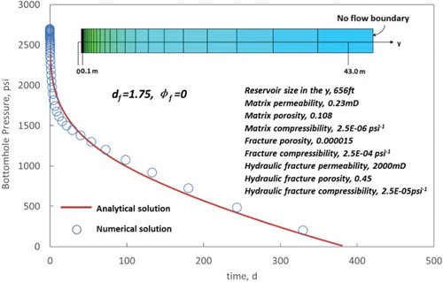
To verify the accuracy of the above mathematical model and analytical solutions, a synthetic numerical example is applied with a multi-fractured horizontal well in tight oil using ECLIPSE. To mimic the features of the above description of the heterogeneity of both primary fracture conductivity and permeability within SRV, a logarithmic grid refinement (LGR) method is employed by defining each grid with different values of permeability and porosity. Figure shows the comparison of bottom-hole pressure between the numerical simulation and semi-analytical solutions for a case with df = 1.75, φf = 0. The excellent agreement indicates reasonable accuracy of the above analytical solutions.
Figure 6. Comparison of bottom-hole pressure between semi-analytical model and commercial simulator.
In addition, the above analytical solutions are verified by comparing them to the results of Ozkan et al. (2009), with the assumption of uniform fracture properties along MFHW, where df = dF = dm = 2 and θm = θf = θF = 0. As shown in Figure , comparative analysis reveals reasonable agreement. The values of parameter inputs for the model verification has been added in .
Figure 7. Comparison of analytical solution to model proposed by Ozkan et al. (Citation2009).
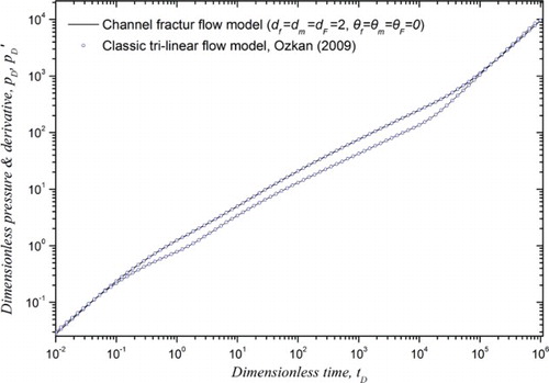
Table 1. Data used in the comparative analysis.
4. Results and discussion
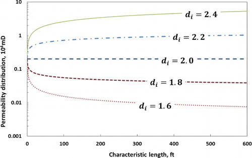
Figure shows the cases with different fractal dimensions. The characteristic length represents the distance from the starting points (i.e. wellbore or center of primary fracture) to the location of study points (i.e. inside primary fracture or SRV). The fractal dimension ‘2’ indicates the case with homogeneous distribution of fracture permeability, which is the example of conventional hydraulic fracturing. However, after implementing channel fracturing, due to the heterogeneous placement of proppant pack inside the primary fracture, the fractal dimension of the hydraulic primary fracture becomes larger than ‘2’. As a result, an increasing trend of fracture permeability with respect to characteristic length is induced for the channel-fracturing case. In addition, with the increase of fractal dimensions, the average values of fracture permeability also increase, which means the enhancement of the conductivity of average hydraulic fractures. However, within SRV, because of both the attenuation of fracturing energy and amounts of packed proppant as SRV propagates, the permeability shows a decreasing trend along the direction of SRV width. Hence, in this region, the fractal dimension becomes less than ‘2’.
Figure 8. Permeability distribution with respect to fractal dimension di.
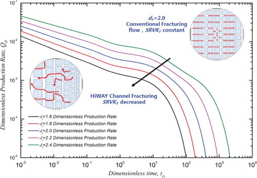
The effects of the fractal dimension (dF and df) of both primary fracture and SRV on production rates are evaluated in Figures –. Figure presents the impacts of the fractal dimension of the hydraulic fracture on well productivity. The larger the fractal dimension of the primary hydraulic fracture, the stronger the packed extent of proppant leading to higher well production. In addition, the fractal dimension of the primary fracture also has significant effects on long-term well production throughout the entire production period. Figure indicates the impacts of SRV fractal dimension on well performance. The larger the fractal dimension of SRV, the more complex the fracture networks within SRV. With the increase of the fractal dimension, the increased average permeability inside SRV results in more oil production.
Figure 9. Effect of primary fracture fractal dimension dF on well performance (hydraulic fracture).
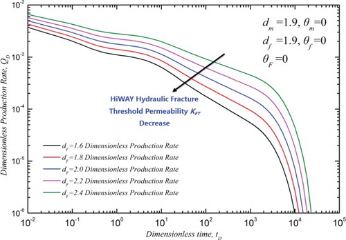
Figure 10. Effect of SRV fractal dimension df on well performance (stimulated reservoir volume).
Figures and show the effects of the fractal connectivity-index of both the matrix system, , and SRV system,
. The results indicate that the connectivity-index has negative effects on fluid flow capacity. The higher connectivity index of both the matrix and the fracture network, the lower the oil production performance. Figure indicates that the effects of the fractal connectivity-index of the primary fracture,
, can have a significant effect on well performance from the early to the intermediate production period. As for long-term production, the effects of the connectivity-index would disappear. Figure represents the impact of the fractal matrix system connectivity index,
, on well performance. It has significant effects on production rate from the intermediate to the late production period. The different influencing periods of the fractal connectivity-index in the matrix system or fracture system may be attributed to their different contributions to well production at different production times. Due to the rapid fluid outflows from the highly conductive fracture system, the contribution of the fracture system mainly occurs during the early to intermediate production periods. After this, the fluid flow in the matrix reservoir starts to work.
Figure 11. Effect of connectivity index on fracture network system (stimulated reservoir volume).
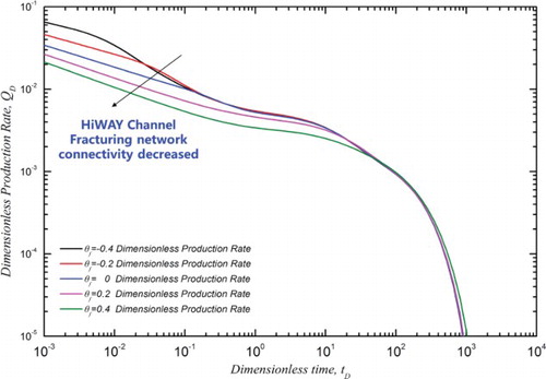
Figure 12. Effect of connectivity index on fractal matrix system (stimulated reservoir volume).
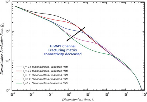
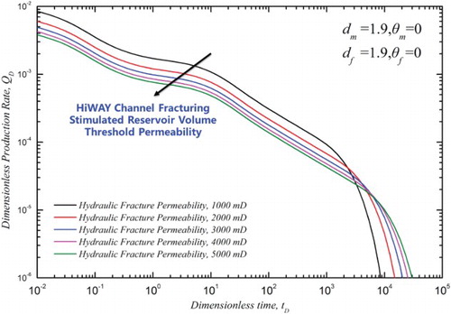
Figure shows the effects of primary hydraulic fracture conductivity on the distribution of permeability within SRV. As the values of primary fracture conductivity increase, the threshold permeability of kf at the boundary of SRV is also enhanced. As well performance with different primary fracture conductivity (see Figure ) demonstrates, the choice of a highly-conductive primary fracture has a significant impact on production performance throughout well life. This is because enhancement of primary fracture conductivity not only leads to a decrease in fluid flow resistance inside the primary fracture but also results in significant improvement in fluid flow capacity within SRV in reservoirs.
Figure 13. Permeability distribution within SRV caused by the increase of primary fracture conductivity.
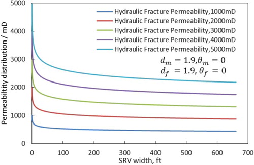
Figure 14. Effect of hydraulic fracture permeability on dimensionless well production rate.
Conclusions
In this article, unlike the conventional fracture model with uniform distribution of fracture proppant, a novel analytical solution incorporated with the fractal theory in the tri-linear flow model was presented for a channel-fractured horizontal well. The new model is verified by both numerical simulations and existing simplified models. The main findings and conclusions can be concluded as follows:
Our model can account for both the heterogeneities of fracture/matrix systems within dual-porosity SRV and non-uniform distribution of proppant pack inside hydraulic primary fractures.
The different influencing periods of the fractal connectivity-index in the matrix and fracture systems on well production are characterized.
An increase of the fractal dimension within SRV or a primary fracture results in greater oil production.
The enhancement of primary fracture conductivity not only leads to a decrease in fluid flow resistance inside a primary fracture, but also results in significant improvement in fluid flow capacity within SRV in reservoirs.
Nomenclature
| = | Volume factor under initial condition, dimensionless | |
| = | Hydraulic fracture half-width (cm) | |
| = | Dimensionless hydraulic fracture half-width (cm) | |
| = | Dimensionless wellbore storage coefficient | |
| = | Matrix bulk compressibility (atm−1) | |
| = | Fracture bulk compressibility (atm−1) | |
| = | Total compressibility of hydraulic fracture, region 1 (atm−1) | |
| = | Total compressibility in SRV, region 2 (atm−1) | |
| = | Fractal dimension (dimensionless) | |
| = | Connectivity index (dimensionless) | |
| = | Reservoir thickness (cm) | |
| = | Matrix bulk permeability (D) | |
| = | Fracture bulk permeability at the edges of the hydraulic fracture, region 2 (D) | |
| = | Hydraulic fracture permeability (D) | |
| = | Dimensionless pressure | |
| = | Matrix pressure in SRV, region 2 (atm) | |
| = | Fracture pressure in SRV, region 2 (atm) | |
| = | Production rate (cm3/s) | |
| qD | = | Production rate (cm3/s) |
| = | Skin factor | |
| = | Dimensionless time | |
| = | Time (s) | |
| = | Hydraulic fracture half-length (cm) | |
| = | Reservoir size in x-direction (cm) | |
| = | Dimensionless hydraulic fracture half-length in x-direction | |
| = | Reservoir size in y-direction (cm) | |
| = | Dimensionless hydraulic fracture half-length in y-direction | |
| = | Flow capacity coefficient | |
| = | Storability ratio | |
| = | Total formation porosity in SRV, region 2 | |
| = | Hydraulic fracture porosity in region 1 | |
| = | Matrix porosity | |
| = | Formation oil density (g/cm3) | |
| = | Oil viscosity (cp) | |
| = | Matrix shape factor in dual-porosity model |
Acknowledgements
The authors would like to acknowledge the technical support of ECLIPSE.
Disclosure statement
No potential conflict of interest was reported by the authors.
Additional information
Funding
Related Research Data
References
- Abdulal, H. J., Samandarli, O., & Wattenbarger, B. A. (2011, November 15–17). New type curves for shale gas wells with dual porosity model. Canadian unconventional resources conference, Calgary, Alberta, Paper No. SPE 149367.
- Altman, R. M., Viswanathan, A., Xu, J., Ussoltsev, D., Indriati, S., Grant, D., … Kirkham, B. (2012, April 16–18). Understanding the impact of channel fracturing in the eagle ford shale through reservoir simulation. SPE Latin America and Caribbean petroleum engineering conference, Mexico City, Mexico, Paper No. SPE 153728.
- Bowman, F. (1985). Introduction to bessel functions. New York: Dover Publications Edition.
- Britt, L. K., & Bennett, C. O. (1985, September 22–26). Determination of fracture conductivity in moderate-permeability reservoirs using bilinear flow concepts. SPE annual technical conference and exhibition, Las Vegas, Nevada, Paper No. SPE 14165.
- Britt, L. K., & Smith, M. B. (2009, September 23–25). Horizontal well completion, stimulation optimization, and risk mitigation. SPE eastern regional meeting, Charleston, West Virginia, Paper No. SPE 125526.
- Clarkson, C. R. (2013). Production data analysis of unconventional gas wells: Review of theory and best practices. International Journal of Coal Geology, 109–110(0), 101–146. doi: 10.1016/j.coal.2013.01.002
- Costantini, A., Falcone, G., Hewitt, G. F., & Alimonti, C. (2008). Using transient inflow performance relationships to model the dynamic interaction between reservoir and wellbore during pressure testing. Journal of Energy Resources Technology, 130(4), 042901-1–042901-9. doi: 10.1115/1.3000128
- Denney, D. (2010). Fluid selection for energized hydraulic fractures. Journal of Petroleum Technology, 62(03), 42–44. doi: 10.2118/0310-0042-JPT
- Economides, M. J., & Nolte, K. G. (2000). Reservoir stimulation (3rd ed.). Chichester: John Wiley & Sons.
- Ejofodomi, E. A., Cavazzoli, G., Morris, J., & Prioul, R. (2014, May 21–23). Application of channel fracturing in the vaca muerta shale formation. SPE Latin America and Caribbean petroleum engineering conference, Maracaibo, Venezuela, Paper No. SPE 169383.
- Gillard, M. R., Medvedev, O. O., Hosein, P. R., Medvedev, A., Peñacorada, F., & Huteau, E. (2010, September 19–22). A new approach to generating fracture conductivity. SPE annual technical conference and exhibition, Florence, Italy, Paper No. SPE 135034.
- Guo, J., Zhang, S., Zhang, L., Qing, H., & Liu, Q. (2012). Well testing analysis for horizontal well with consideration of threshold pressure gradient in tight gas reservoirs. Journal of Hydrodynamics, Ser. B, 24(4), 561–568. doi: 10.1016/S1001-6058(11)60278-3
- Huang, Y., Zhang, N., & Pei, Y. (2013). Well-balanced finite volume scheme for shallow water flooding and drying over arbitrary topography. Engineering Applications of Computational Fluid Mechanics, 7(1), 40–54. doi: 10.1080/19942060.2013.11015452
- Inyang, U. A., Nguyen, P. D., & Cortez, J. (2014, April 1–3). Development and field applications of highly conductive proppant-free channel fracturing method. SPE unconventional resources conference, The Woodlands, Texas, Paper No. SPE 168996.
- Johnson, J. L., Turner, M. G., Weinstock, C. T., Pena, A. A., Laggan, M. J., Rondon, J. R., & Lyapunov, K. (2011, January 24–26). Channel fracturing – a paradigm shift in tight gas stimulation. SPE hydraulic fracturing technology conference, The Woodlands, Texas, Paper No. SPE 140549.
- Mayerhofer, M. J., Lolon, E., Warpinski, N. R., Cipolla, C. L., Walser, D. W., & Rightmire, C. M. (2010). What is stimulated reservoir volume? SPE Production & Operations, 25(01), 89–98. doi: 10.2118/119890-PA
- Medvedev, A. V., Kraemer, C. C., Pena, A. A., & Panga, M. K. R. (2013, February 4–6). On the mechanisms of channel fracturing. SPE hydraulic fracturing technology conference, The Woodlands, Texas, Paper No. SPE 163836.
- Ozkan, E., Brown, M. L., Raghavan, R. S., & Kazemi, H. (2009, March 24–26). Comparison of fractured horizontal-well performance in conventional and unconventional reservoirs. SPE western regional meeting, San Jose, California, Paper No. SPE 121290.
- Ozkan, E., Raghavan, R. S., & Apaydin, O. G. (2010, September 19–22). Modeling of fluid transfer from shale matrix to fracture network. SPE annual technical conference and exhibition, Florence, Italy, Paper No. SPE 134830.
- Selimefendigil, F. (2013). Numerical analysis and pod based interpolation of mixed convection heat transfer in horizontal channel with cavity heated from below. Engineering Applications of Computational Fluid Mechanics, 7(2), 261–271. doi: 10.1080/19942060.2013.11015469
- Stalgorova, E., & Mattar, L. (2012, October 30–November 1). Analytical model for history matching and forecasting production in multifrac composite systems. SPE Canadian unconventional resources conference, Calgary, Alberta, Paper No. SPE 162516.
- Stephens, W. T., Schubarth, S. K., Dickson, K. R., Snyder, E. M., Doles, K., & Herndon, D. C. (2007, January 29–31). Behavior of proppants under cyclic stress. SPE hydraulic fracturing technology conference, College Station, Texas, Paper No. SPE 106365.
- Vincent, M. C. (2009, January 19–21). Examining our assumptions — have oversimplifications jeopardized our ability to design optimal fracture treatments? SPE hydraulic fracturing technology conference, The Woodlands, Texas, Paper No. SPE 119143.
- Wang, C., & Wu, Y.-S. (2013). Characterizing hydraulic fractures in shale gas reservoirs using transient pressure tests. Society of Petroleum Engineers. doi: 10.2118/163819-MS
- Wang, D., Ge, H., Wang, X., Wang J., Meng F., Suo Y., & Han, P. (2015). A novel experimental approach for fracability evaluation in tight volcanic rock gas reservoirs. Journal of Natural Gas Science and Engeering, 23, 239–249. doi: 10.1016/j.jngse.2015.01.039
- Wang, W., Shahvali, M., & Su, Y. (2015). A semi-analytical fractal model for production from tight oil reservoirs with hydraulically fractured horizontal wells. Fuel, 158(0), 612–618. doi: 10.1016/j.fuel.2015.06.008
- Wang, W., Su, Y., Sheng, G., Cossio, M., & Shang, Y. (2015). A mathematical model considering complex fractures and fractal flow for pressure transient analysis of fractured horizontal wells in unconventional reservoirs. Journal of Natural Gas Science and Engineering, 23(0), 139–147. doi: 10.1016/j.jngse.2014.12.011
- Wang, W., Su, Y., Zhang, X., Sheng, G., & Ren, L. (2015). Analysis of the complex fracture flow in multiple fractured horizontal wells with the fractal tree-like network models. Fractals, 23(02), 1550014-1–1550014-9. doi: 10.1142/S0218348X15500140
- Wang, X., Zhou, Y., & Luo, W. (2010). A study on transient fluid flow of horizontal wells in dual-permeability media. Journal of Hydrodynamics, Ser. B, 22(1), 44–50. doi: 10.1016/S1001-6058(09)60026-3
- Yuan, B., Su, Y., Moghanloo, R. G., Rui, Z., Wang, W., & Shang, Y. (2015). A new analytical multi-linear solution for gas flow toward fractured horizontal wells with different fracture intensity. Journal of Natural Gas Science and Engineering, 23(0), 227–238. doi: 10.1016/j.jngse.2015.01.045
- Yudin, A. V., Sadykov, A., Oparin, M., Efremov, A., Doktor, S. A., Katrich, N. M., … Rudnitsky, A. A. (2012, October 16–18). Channel fracturing in the remote Taylakovskoe oil field: Reliable stimulation treatments for significant production increase (Russian). SPE Russian Oil and Gas exploration and production technical conference and exhibition, Moscow, Russia, Paper No. SPE 160767.
- Zhao, Y.-L., Zhang, L.-H., Luo, J.-X., & Zhang, B.-N. (2014). Performance of fractured horizontal well with stimulated reservoir volume in unconventional gas reservoir. Journal of Hydrology, 512(0), 447–456. doi: 10.1016/j.jhydrol.2014.03.026