
ABSTRACT
The complicated flows in a transonic cantilevered stator would cause serious aerodynamic losses and reducing these losses would contribute much to improving the overall aerodynamic performance of a compressor. The paper conducts an overview study of the potential aerodynamic losses in a transonic cantilevered stator and presents a systematic numerical study for the effects of forward end sweep on reducing aerodynamic losses. A 2-D stator blade is used to throw light upon the physical mechanism of the forward end sweep on reducing the losses. At the casing region, forward end sweep has led to a redistribution of the blade load along the chordwise direction, higher in the front part and lower in the rear part. This result leads to a lower pressure gradient from the 30% chord location to the trailing edge and can be beneficial for the reduction of the corner separation. At the hub region, on one aspect, forward end sweep reduces both the peak Mach number and the size of the high-Ma region of the blade suction surface, thus decreasing the shock loss near the hub. On the other aspect, it also reduces the peak load and the strength of the leakage vortex, therefore alleviating the flow blockages. Simultaneously, the forward end sweep is applied to a commercial and high-performance multistage compressor to further validate its feasibility. When the technique is applied to the transonic first four stator rows, an improvement of adiabatic efficiency is achieved by ∼ 0.85% and the compressor stable operating range is slightly increased. The results suggest that the forward end-swept transonic cantilevered stators have a significant potential for reducing the stator losses. They would provide guidelines to advance the cantilevered stator design and further improve the compressor aerodynamic performance.
Abbreviations: h, stagnation enthalpy; , stagnation pressure; p, static pressure; U, blade rotational speed at tip; V, velocity;
, non-dimensional wall distance;
, total pressure loss coefficient;
, flow coefficient (Vx/U);
, stage load coefficient (Δh/U2);
, adiabatic efficiency;
, total pressure ratio; in, inlet; out, outlet; LE/TE, leading/trailing edge; PS/SS, pressure/suction surface
1. Introduction
The demand of high aerodynamic performance and low fuel consumption for modern aero-engines has made their compression system toward high load and wide operating range. In this situation, it is required that the stage of a compressor provide both a high pressure ratio and high adiabatic efficiency. To meet the requirements, transonic compressor rotors are developed. The demand of high load and high adiabatic efficiency for transonic rotors would inevitably deteriorate the downstream stator performance and increase the difficulty of stator design. Therefore, advanced stator designs are very essential because they play a significant role in overall aerodynamic performance of a compressor. Based on these points, three-dimensional (3-D) design concepts (non-radial stacking blading) are introduced to design advanced stators (Gallimore et al., Citation2002a, Citation2002b; Smith & Yeh, Citation1963).
As one of the important 3-D blade design concepts, sweep has been extensively applied in transonic rotors to decrease the shock loss and improve the aerodynamic performance (Benini & Biollo, Citation2007; Denton & Xu, Citation2002; Hah, Puterbaugh, & Wadia, Citation1998; Wadia, Hah, & Rabe, Citation2004; Wadia, Szucs, & Crall, Citation1998), but the open reports on its application to stator blade design are limited (Denton & Xu, Citation1998; Gallimore et al., Citation2002a). In the past two decades, only a few experimental or theoretical studies have investigated the sweep application to the stators. In detail, Sasaki and Breugelmans (Citation1998) carried out a parametric study and found that the beneficial effects of forward sweep were due to delaying the corner separation onset. Friedrichs, Baumgarten, Kosyna, and Stark (Citation2001) reported that, compared with a conventional stator, a better aerodynamic performance at the hub could be achieved by the stator with an after-sweep leading edge, where the sweep angle is increased toward both the hub and the casing ends. Gümmer, Wenger, and Kau (Citation2001) tried to use sweep and dihedral to control the complex 3-D flow in a transonic stator of an axial compressor and observed that positive sweep was beneficial for the end-wall low-energy fluid transporting to the mid-span, which would enhance the radial mixing.
The aforementioned sweep applications are only limited to shrouded stators. However, currently, low fuel consumption and high thrust-to-weight ratio are urgently required for both civil and military aircraft engines. In this situation, the combination of integrally bladed rotors and high-load cantilevered stators is gradually applied to the small aero-engine compressors to reduce the weight of the compression system. Moreover, compared with hub shrouded stators, cantilevered stators also have some aerodynamic advantages (Campobasso, Mattheiss, & Wenger, Citation1999; Freeman, Citation1985; Si, Teng, Qiang, & Feng, Citation2017) and have also been applied to axial-flow compressors in large industrial gas turbines (Yoon, Selmeier, Cargill, & Wood, Citation2015). However, the potential aerodynamic losses in a high-load cantilevered stator are complicated and would have a significant impact on the overall performance of a compressor. Due to the demand for the high aerodynamic performance of the axial-flow compressors, the techniques which could advance the cantilevered stator designs are essential.
In open literature, there are few reports on the application of sweep to transonic cantilevered stators. Only the earlier research by Tweedt, Okiishi, and Hathaway (Citation1986) experimentally studied the influence of the leading-edge sweep toward end-walls on decreasing the aerodynamic losses near the casing in a subsonic stator passage. They reported that the swept leading edge appeared to succeed in drawing high-momentum flow to the corner region of the suction surface and, therefore, suppressing the viscous flow region thickening.
To advance the design of cantilevered stators, the paper conducts an overview study of the potential losses in a transonic cantilevered stator blade and explores the effect of forward end sweep on the cantilevered stator losses. The motivation is to provide insight into how the forward end sweep would affect the cantilevered stator losses and evaluate the potential aerodynamic benefits, and further provide guidelines for designing advanced cantilevered stators.
2. Main losses in cantilevered stators
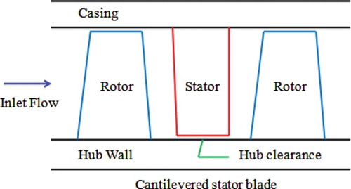
For a cantilevered stator configuration, stator vanes are attached at the casing only, but are free at the hub end, thus being cantilevered. Therefore, there is a running clearance between the hub wall and the stator vane. Figure gives a description of a cantilevered stator configuration in a compressor. There would be potential aerodynamic losses occurring at both the hub and the casing end-wall regions in a transonic cantilevered stator.
Figure 1. Schematic descriptions of a cantilevered stator in a compressor.
2.1. Losses in casing end-wall region
In a cantilevered stator passage, it's more likely for the flow in the suction surface corner of the casing end-wall region to get separated. It needs to be stressed that corner separations can occur in a well-designed stator of a compressor, even in the design working condition (Weingold, Neubert, Behlke, & Potter, Citation1997). Investigations on the corner separations in a stator passage have been conducted by Joslyn and Dring (Citation1985), Dong, Gallimore, and Hodson (Citation1986) and Schulz and Gallus (Citation1988). For a high-load cantilevered stator, reducing the corner separations in the end-wall region can lead to some extent of aerodynamic benefits achievements.
2.2. Losses in hub region
The leakage flow in a cantilevered stator passage driven by the pressure gradient between the pressure and suction surfaces flows into the blade passage and mixes strongly with the main flow, leading to the leakage vortex at the location where the maximum load point occurs (Storer & Cumpsty, Citation1991). The hub leakage vortex would have an impact on the aerodynamic losses and the flow blockages in the hub region. In addition, since there are transonic regions near the hub region of the blade inlet due to the highly loaded upstream rotor, the high inlet Mach number would result in high aerodynamic losses on the stator suction surface, thus leading to a great shock loss near the hub.
3. Cantilevered stator blade geometry
3.1. Baseline stator
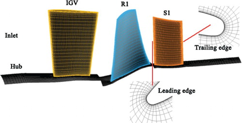
In this study, to obtain a real inlet working conditions of the investigated stator, the inlet guide vane and the upstream rotor are considered. Figure depicts the 1.5-stage transonic axial compressor in which the combination of cantilevered stators (S1) and integrally bladed rotors (R1) is applied. Attention is paid to the cantilevered stator blade. The baseline stator, 2-D radially stacking blading in geometry, provides the baseline data to make comparisons with those from other modified stators. The main geometrical and operational parameters are given in Table . The purpose of using the 2-D stator blade is to clearly explain and reveal the mechanism of forward end sweep.
Figure 2. The 1.5-stage transonic axial compressor.
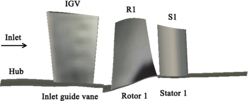
Table 1. Geometric and operational parameters related to the compressor.
3.2. Forward end swept stator
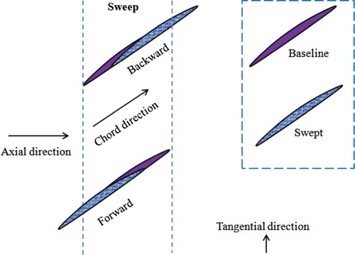
In this work, sweep is defined through the movements of the airfoil sections along the chordwise direction. Figure gives a schematic description of the sweep definition. When a blade airfoil section moves upstream, a forward sweep is obtained, while a movement toward the opposite direction would lead to a backward sweep.
Figure 3. Schematic of the blade sweep.
The swept stator is obtained by optimizing the baseline stator through an integrated surrogate-based optimization design procedure, as shown in Figure . The optimization procedure includes a geometry parameterization tool, an efficient surrogate modeling approach, a reliable flow solver and an efficient optimization tool.
Figure 4. Flow chart of the surrogate-based optimization procedure.
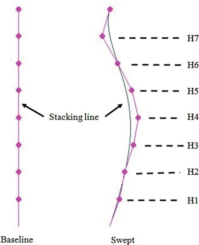
As described in Figure , the n-parameter Bezier function is used to parameterize the stacking line. A new swept stator is modeled through the change of the stacking line curvature along the chordwise direction. On the stacking line, seven uniformly distributed control points are employed to control the curvature. Swept stators are obtained by moving the control points in the chordwise direction, while both the hub and casing ends are unchanged. Seven non-dimensional parameters (H1-H7) are used to describe the chordwise offsets of the control points.
Figure 5. The comparison of the stacking line of the baseline and swept stator.
The optimization procedure starts from the geometry parameterization. In this process, key geometric parameters which have significant influences on the compressor aerodynamic performance are usually selected as the design variables. In the meanwhile, the optimization objectives and the variation ranges of the design variables are determined according to the specific feature of the problem and the real geometrical constraints. Then, a design of experiment method is used to establish a sample database and an efficient surrogate model is created to relate the optimization objectives and the design variables. Finally, an optimization searching method will be applied to the surrogate model to get the optimal solutions.
The artificial neural network (ANN) has been employed to relate the optimization objectives and the design variables. To establish the ANN model, a Latin hypercube sampling approach has been adopted to create a sample database in which the corresponding aerodynamic performances are predicted by the CFD simulations. In this study, 60 sampling points are used to create the ANN surrogate model for predicting the compressor performance. After the ANN model is established, the genetic algorithm (GA) embedded in MATLAB is employed to find the optimal solution. To set up the GA, the population size and the generation number are both set to be 100, and the rank fitness scaling strategy is used. This searching process stops until it reaches the maximum number of generations and then the optimal solution is obtained.
The optimization design process in this study is conducted at the near peak efficiency working point. In detail, the three basic elements, the optimization objectives, design variables and constraints, can be described as follows:
3.2.1. Objectives
The objective is to improve the adiabatic efficiency:
(1) where
represents the adiabatic efficiency.
3.2.2. Design variables
The non-dimensional parameters (H1–H7), the chordwise offsets of the control points, are selected as the design variables.
3.2.3. Constraints
3.2.3.1. Geometrical constraints
The hub and shroud profile, the blade thickness, the radius of the leading and trailing edges and the camber line do not change. Moreover, the moving offsets of the control points are also constrained by less than 40% of the axial gap between the rotor and stator in the multistage environment.
3.2.3.2. Performance constraints
The total pressure ratio should be maintained:
(2) where
and
are the objective pressure ratio of the optimized compressor and the original pressure ratio of the baseline compressor, respectively.
is an imposed constant value, which is selected to be 0.03 in this work.
In addition, to keep the stable operating range, the modified compressor whose operating range is less than the baseline compressor would be ticked out.
3.2.4. Mathematical model
Based on the above descriptions, the mathematical model of the optimization problem can be expressed as follows:
(3) where x depicts the design variable. The variation ranges of the design variables are normalized.
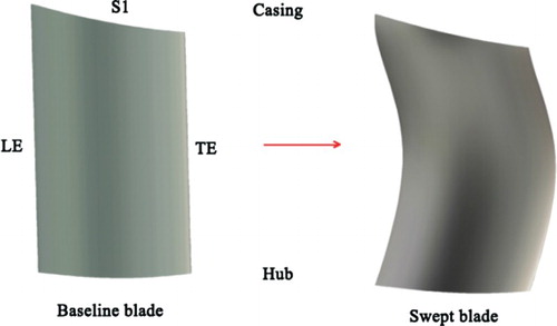
The swept stator, with the character of forward end sweep at both the hub and casing ends, is obtained by solving the optimization problem. Figure gives a description of the comparison of the blade geometries between the baseline stator and the swept one. The motivation is to explore the physical mechanism of the influence of forward end sweep on controlling the stator losses and evaluate the potential aerodynamic benefits gain.
Figure 6. Meridional view of the baseline and swept stators.
4. Research approach
4.1. Numerical technique
The commercial flow solver NUMECA FINE-Turbo is used to perform the numerical computations in this study. The 3-D compressible Reynolds-averaged Navier-Stokes equations are solved to get the solutions. In detail, a finite volume method is used to discretize the governing equations. Meanwhile, an explicit fourth-order Runge–Kutta scheme is used for the temporal discretization and a second-order central-differenced scheme is used for the spatial discretization. The Spalart-Allmaras turbulence model is used in the computations and this is also based on the successful experiences of earlier investigations in turbomachinery (Danish, Khan, Umer, Qureshi, & Ma, Citation2014; Krishnababu et al., Citation2009; Mahesh & Pradeep, Citation2013).
A single-blade passage with periodic boundary conditions is considered. The total pressure and total temperature and the axial flow angle are specified at the compressor inlet. For the compressor outlet, the static pressure is specified. The no-slip and adiabatic conditions are imposed on the solid walls. In addition, the mixing-plane approach is applied to the rotor-stator interface.
In the blade passage, a multi-block O4H structured grid is used with an O-grid surrounding the blade surface (Figure ). The mesh in the calculations is composed of ∼ 1.65 × 10⁶ nodes, with ∼ 0.55 × 10⁶ nodes in each blade domain. There are 73 grid points in the radial direction; 17 grid points are employed in the clearances of the blade hub and tip to get the solutions in these regions. The non-dimensional parameter y+ is kept less than 5 for all the calculations. Meshes for the baseline stator and all remaining modified stators are generated using the same mesh template file by only changing the blade geometry.
Figure 7. Computational grid of the investigated stator.
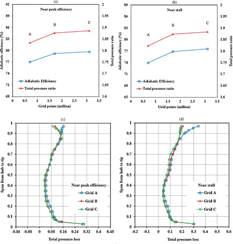
To validate the effect of the mesh size on the computed flow parameters, a grid independence study is conducted at both the near peak efficiency and near stall working conditions, as shown in Figure . Three meshes (Grid A, Grid B and Grid C) are used to carry out the simulations with identical boundary conditions. At the near peak efficiency condition in Figure (a), for the compressor adiabatic efficiency, only 0.6% variation is found when the mesh varies from B to C, which is much smaller than the 2.9% variation when the mesh varies from A to B. With respect to the pressure ratio, only 0.5% variation is found when the mesh varies from B to C. It is much smaller than the 2.3% variation when the mesh varies from A to B. At the near stall condition in Figure (b), for the compressor adiabatic efficiency, only 0.9% variation is observed when the mesh varies from B to C, compared with the 3.9% variation when the mesh varies from A to B. With respect to the total pressure ratio, only 0.5% variation is found when the mesh varies from B to C, which is much smaller than the 2.8% variation when the mesh varies from A to B. At the same time, for both the near peak efficiency and near stall conditions shown in Figures (c and d), Grid A has over-predicted the stator aerodynamic losses near the casing, while the predictions given by Grids B and C have the same variation trends and approximate values along the radial direction. In view of the computation accuracy and cost, Grid B is used to perform the numerical simulations.
Figure 8. Grid independence study.
The computations will converge when the variation of the mass flow between the inlet and the outlet becomes no more than 10−5 for the last 100 steps. In the final computational steps, the relative change of the mass flows between the inlet and the outlet becomes no more than 0.02%. All the numerical simulations are conducted on a PC with Intel Core (8 CPUs).
4.2. CFD validations
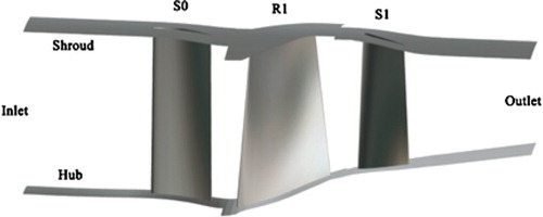
Since there doesn't exist experimental data for this single-stage compressor, to validate the CFD method and tool adopted in this work, CFD validations are carried out based on a well experimented axial compressor. A description of the compressor in which the stator (S1) is hub shrouded is shown in Figure .
Figure 9. Schematic of the tested axial-flow compressor.
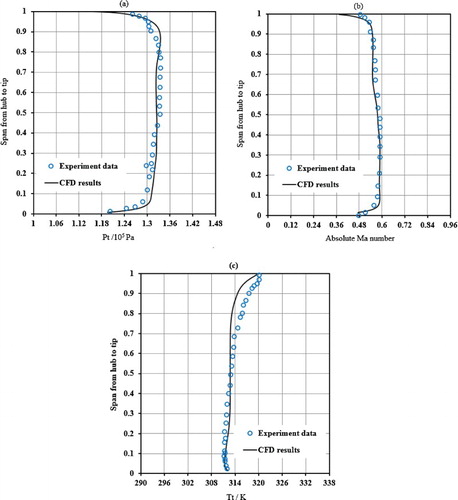
The detailed experiments are performed on a 3.5-stage axial compressor and this compressor is extended based on the 1.5-stage one. The experimental data (Wang, Citation2007) are extracted from the 3.5-stage compressor. In the actual numerical computations, the radial distribution of the static pressure at the stator (S1) outlet is extracted from the experimented compressor. It is then imposed onto the outlet of the stator S1 in the 1.5-stage axial compressor. Figure shows the comparisons between the CFD results and the experiment. It is found that the CFD results have good agreement with the experimental data.
Figure 10. Comparisons between the CFD results and the experimental data.
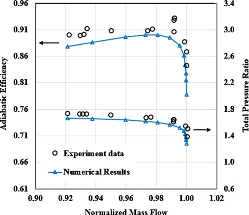
Then the CFD validations are also conducted based on the well documented transonic compressor rotor NASA Rotor 67 (Strazisar, Wood, Hathaway, & Suder, Citation1989). Figure describes the comparison of the performance maps between the CFD results and the experimental data. It is observed that the CFD tool has given slightly lower predictions for both the adiabatic efficiency and the total pressure ratio over the whole operating range. Overall, the CFD results provide quite good agreement with the experimental data.
Figure 11. Comparison of the performance maps between the CFD results and the experimental data.
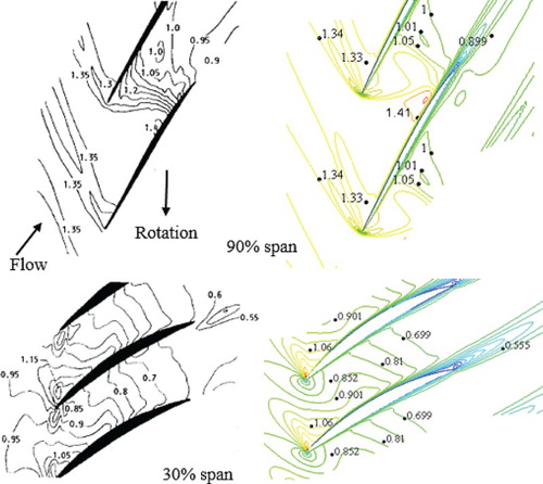
As shown in Figure , the relative Mach number of distributions are compared between the CFD results and the experimental data at both the 30% and 90% blade span. These two blade spans are selected because they characterize the subsonic and transonic flow structures, respectively. Quite a good agreement of the flow structure and the relative Mach number distributions in the blade passage between the CFD results and the experiment has been observed.
Figure 12. Comparison of the relative Mach number distributions between the CFD results and the experimental data.
The validation work of the NUMECA FINE-Turbo has also been done by other researchers. Wang, Chen, Wu, and Ren (Citation2014) have shown good agreements of compressor performance maps between the computed results and the experimental data in a counter-rotating axial compressor when using the Spalart-Allmaras model. Lange, Vogeler, Mailach, and Gomez (Citation2013) have shown that the NUMECA FINE-Turbo-computed blade pressure distributions have quite good agreement with the experiment. In addition, the separations predicted by the Spalart-Allmaras model are validated by using the k-ε model, indicating that the achieved results are not the function of the turbulence model. The aforementioned results indicate the NUMECA FINE-Turbo can provide reliable and accurate flow-field predictions in an axial-flow compressor.
5. Results and discussion
Computational results of the 2-D stator blade are used to throw light upon the potential physical mechanism, and then the forward end sweep is applied to a commercial multistage compressor to further validate its feasibility. First, the focus is on the effects of forward end sweep on the separation loss near the casing, including the comparison of flow-field details. Second, the investigations are shifted to the stator hub end, identifying the influences of forward end sweep on the losses there, including the hub leakage loss and the shock loss. Finally, the technique of forward end sweep is applied to a modern industrial multistage axial-flow compressor to make an improvement of the aerodynamic performance.
5.1. Effect of forward end sweep on the losses at casing end
At the casing end, the blade section often works in harsh conditions. Separations can occur even at the design working condition. The flow separations in this region will have a significant effect on the stator aerodynamic losses and even the entire compressor performance.
Figure shows the incidence change relative to the baseline stator after the application of sweep. It is observed that the forward sweep near the casing has reduced the local incidence. This means that the local mass flow rate will be increased. This change will have a significant influence on the load distribution along the chordwise direction in the casing end-wall region.
Figure 13. The incidence change relative to the baseline stator near the casing.
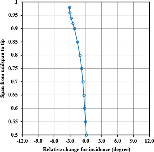
Figure. 14. Comparison of the pressure and load distributions between the baseline and swept blades at 90% span.
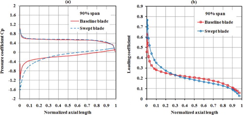
As described in Figure , the blade load of the swept stator becomes higher in the front part and lower in the rear part than that of the baseline stator. To describe the static pressure distribution on the blade surface, the pressure coefficient is employed and expressed as:
(4) where Pwall is the static pressure on the blade surface. At the same time, the load coefficient of the blade is defined as:
(5) where Pps and Pss represent the static pressure on the pressure and suction surfaces, respectively. As shown in Figure (a), the static pressure on the pressure surface for the swept blade is approximately the same with that for the baseline blade, while the static pressure on the suction surface for the swept blade presents a trend of lower in the front part and higher in the rear part compared with that for the baseline blade. The static pressure distributions of the baseline and swept blades have led to the load distribution depicted in Figure (b).
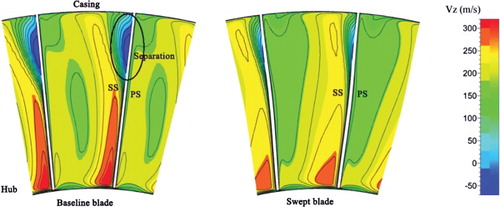
The load distribution on the suction surface for the swept blade results in a smaller pressure gradient from the 30% chord location to the trailing edge and will delay the onset of flow separation. The axial velocity contours at the outlet of the baseline and the swept stators are shown in Figure . For the baseline blade, reverse axial flows can be observed on the suction surface near the casing. This indicates that the flows get separated in this region. As the blade sections are forward swept in the casing region (from the midspan to the casing), it can be observed that the size of the reverse axial flow region is reduced. This improvement in the flow field leads to a reduction of the aerodynamic loss here. The results have demonstrated a key point that the forward sweep at the casing end could effectively reduce the corner separation loss in this region.
Figure 15. Axial velocity contours for the baseline and swept stators at the stator outlet.
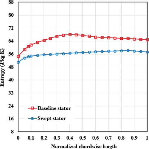
At the same time, the pitch-average entropy distribution from the stator inlet to the outlet is compared near the casing. As shown in Figure , after the sweep application, the flow losses have been decreased along the streamwise direction. The results indicate that the forward sweep near the casing has a beneficial effect on the reduction of the aerodynamic losses in the blade passage.
Figure 16. Comparison of the pitch-average entropy distribution along the streamwise direction between the baseline and swept stators near the casing.
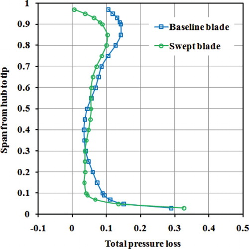
The comparison of the overall aerodynamic losses in the radial direction for the baseline and swept stators is described in Figure . To measure the variation of the stator aerodynamic losses, the total pressure loss coefficient is used and defined as follows:
(6) where
and
are the total pressures at the stator inlet and outlet and
represents the static pressure at the stator inlet. It can be found that the forward end swept stator suffers less aerodynamic loss in the casing region (from 60% span to the casing) than the baseline stator. Moreover, the aerodynamic benefits gain is more notable near the casing.
Figure 17. Distributions of the aerodynamic losses along the spanwise direction for the baseline and swept stators.
In summary, in the casing end-wall region, forward sweep can reduce the local incidence and redistribute the blade load. The results lead to a lower pressure gradient from the 30% chord length location to the trailing edge and notably reduce the flow separations.
5.2. Effect of forward end sweep on the losses at hub end
In the hub region of the investigated stator, the losses are mainly composed of shock loss and leakage loss. The effects of forward end sweep on these two losses will be discussed in this section.
5.2.1. Shock loss
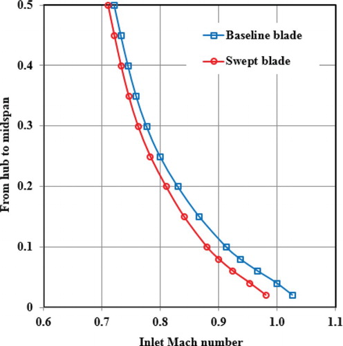
After applying the technique of forward end sweep to the baseline stator, the inlet Mach number has been decreased at the stator hub end. The lower inlet Mach number would cause lower total pressure loss on the stator suction surface (Figure ).
Figure 18. Comparison of the inlet Mach number between the baseline and swept stators.
As can be observed in Figure , the swept stator has achieved a smaller size of supersonic regions and a reduced peak Mach number near the leading edge on the stator suction surface. In this situation, the strength of the shock on the suction surface has been reduced and the shock/boundary layer interaction would be alleviated.
Figure 19. Ma number contours near the blade suction surface.
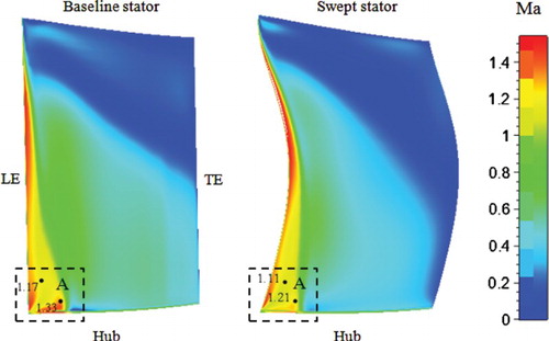
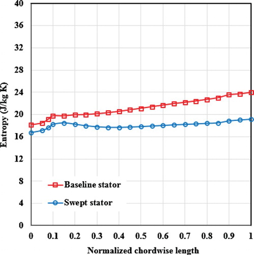
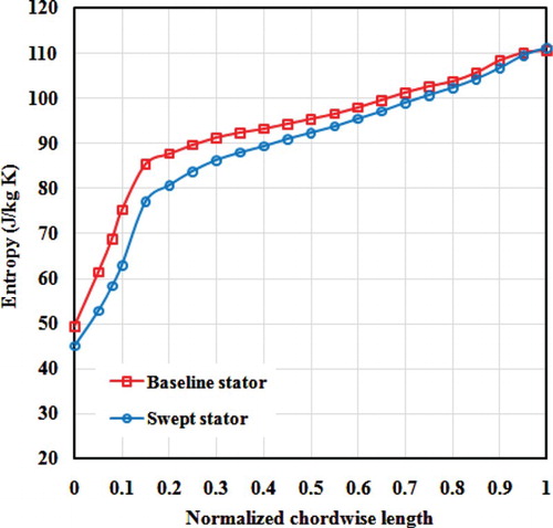
Figure gives a description of the comparison of the pitch-average entropy distribution along the chordwise direction between the baseline and swept stators near the hub. It is observed that, after the application of forward sweep near the hub, the entropy creation along the streamwise direction in the blade passage has been decreased and it means that the aerodynamic loss has been reduced. This is due to the reduction of the size of the high-Ma regions on the suction surface and the shock loss near the leading edge. Therefore, the forward end swept stator has achieved aerodynamic performance improvements near the hub, which corresponds to the results shown in Figure .
Figure 20. Comparison of the pitch-average entropy distribution along the streamwise direction between the baseline and swept stators near the hub (about 10% span).
5.2.2. Leakage loss
The leakage flow in the cantilevered stator passage will inevitably result in the leakage vortex near the hub and further lead to blockages in this region, which will significantly affect the stator performance. The effects of forward end sweep on the leakage flow will be discussed in this section.
The leakage flow, which is driven by the pressure difference between the pressure and suction surfaces, travels across the hub clearance and then flows into the blade passage. The leakage vortex is created by the interaction of the leakage flow and the main flow and accumulates towards the pressure surface of the adjacent blade. The leakage vortex develops along the streamwise direction and would inevitably cause a blockage near the hub wall.
A comparison of the entropy contours near the hub between the baseline stator and the swept stator is made in Figure . With the forward end sweep near the hub, the area of the low-momentum flow region shrinks and the blockage in the hub region is mitigated. This is because the load in the front part of the swept blade is reduced in comparison with that of the baseline blade as described in Figure . As the leading edge is forward swept, the peak load is decreased by ∼ 8% and the load from 3% to 22% axial chord is also reduced. In other words, the leakage flow initiated at the maximum load point is weakened and develops slowly along the streamlines. Therefore, the passage blockages near the hub are alleviated. The computational results suggest that forward end sweep has a positive effect on mitigating the flow blockages in the hub region of a cantilevered stator passage.
Figure 21. Entropy contours on the cross planes of the baseline stator and the swept stator.
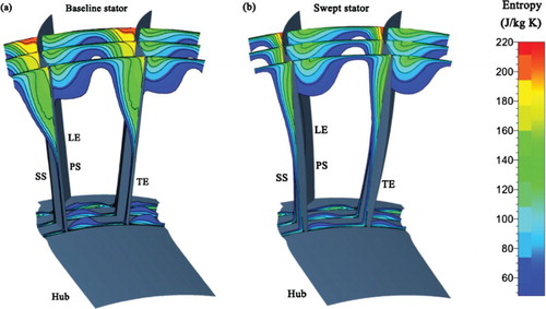
Figure 22. Load distributions of the baseline and swept stators near the hub.
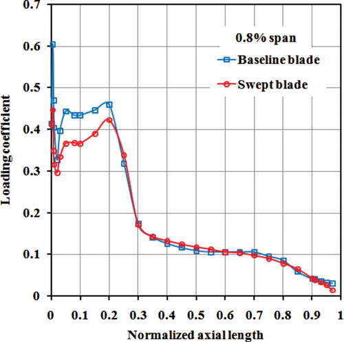
Figure compares the entropy creation near the hub wall along the streamwise direction in the blade passage between the baseline and swept stators. It can be found that the entropy creation has been decreased for the swept blade. The results indicate that the swept stator has suffered less aerodynamic losses along the streamlines near the hub wall.
Figure 23. Comparison of the pitch-average entropy distribution along the streamwise direction between the baseline and swept stators near the hub wall (∼ 0 .4 % span).
In summary, the aerodynamic benefits gain at the stator hub end is due to two aspects. One is that the forward end sweep can reduce the inlet Mach number and the peak Mach number on the suction surface in the hub region, and further decrease the shock loss. The other is that the forward end sweep can reduce the peak load and further the strength of the leakage vortex, thus decreasing the blockages and the corresponding losses near the hub.
5.3. Stator overall performance
Since the technique of forward end sweep has reduced the flow separations near the casing and the passage blockages near the hub, an ∼ 24.5% decrease of the stator aerodynamic losses has been achieved. The computed results are shown in Table . Due to the stator aerodynamic benefits gain, the compressor adiabatic efficiency has been improved by ∼ 1.7%.
Table 2. Comparison of the stator aerodynamic loss.
5.4. Applications to a multi-stage axial-flow compressor
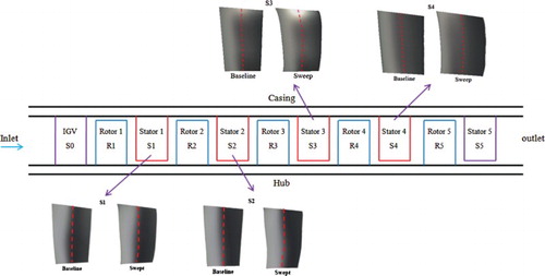
Since the mechanism of forward end sweep is well understood in the stage environment for reducing the aerodynamic losses in a transonic cantilevered stator, the same technique as mentioned in Section 3.2 is then applied to the four stator rows (Stators 1, 2, 3 and 4) in an industrial 5-stage axial-flow compressor. The main purpose is to improve the adiabatic efficiency of the industrial multi-stage compressor. The compressor is a commercial and modern multi-stage axial-flow compressor, and the stators are 3-D designed blades. The reason for choosing these four stators is that there are transonic regions on the suction surface in the stator passages. The key motivation is to further verify the aerodynamic advantages of the technique of forward end sweep. The schematic of the modified stator blades in the multi-stage compressor is shown in Figure .
Figure 24. Schematic of the modified compressor, having forward end swept stators in four stator rows (S1, S2, S3 and S4).
After the modification, it is found that the aerodynamic losses of the four modified stators are notably decreased and the computational results are shown in Table . The aerodynamic losses of the first three stator rows are reduced by 6%–7%, while a reduction of the loss by 11.5% is achieved by the fourth stator row. The results indicate that the application of the forward end sweep has notably reduced the aerodynamic losses of the transonic cantilevered stators.
Table 3. Comparisons of the stator aerodynamic loss between the baseline and modified stators in the multi-stage compressor.
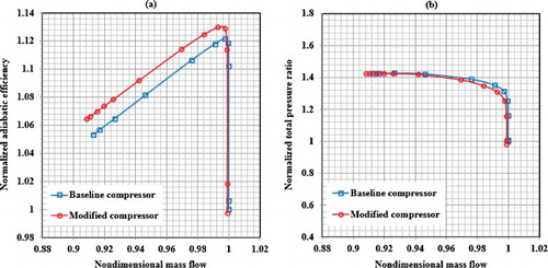
As for the multi-stage compressor, Figure shows the performance maps of the baseline compressor and the modified compressor. The adiabatic efficiency and total pressure ratio have been normalized by the corresponding performance parameters at the choke point. From Figure (a), the results indicate a significant improvement in efficiency from choke to stall. An improvement of adiabatic efficiency is achieved by ∼ 0.85% and the stable operating range is slightly increased. As shown in Figure (b), it is observed that, compared with the baseline compressor, the modified compressor doesn't suffer from a sacrifice for the total pressure ratio and almost maintains the total pressure ratio in the whole operating range. The computed results suggest that the technique of forward end sweep has a positive effect on improving the performance of the transonic cantilevered stators and the entire multi-stage axial-flow compressor.
Figure 25. Performance maps of the baseline and modified compressors.
6. Summary and conclusions
To advance the current design of the cantilevered stator, forward end sweep has been developed and applied to a baseline stator blade to reveal the physical mechanism of the aerodynamic benefits gain and then applied to a modern industrial multi-stage axial-flow compressor for validation. Numerical investigations have been conducted to explore the effects of forward end sweep on transonic cantilevered stator losses including the casing end-wall separation loss, the hub leakage loss and the shock loss. The main findings are summarized as follows:
At the stator casing end, forward end sweep has led to a reduction of the local incidence and a redistribution of the blade load, higher in the front part and lower in the rear part. This result leads to a lower pressure gradient from the 30% chord location to the trailing edge, which is beneficial for the reduction of the separation near the casing.
In the stator hub region, the aerodynamic benefits gain is due to two aspects. On one aspect, forward end sweep has reduced the inlet Mach number and the area of the high-Ma region and peak Mach number, thus reducing the shock loss on the blade suction surface. On the other aspect, forward end sweep has reduced the peak load and decrease the strength of the leakage flow, thus reducing the blockages near the hub wall.
For the stator overall performance, the application of forward end sweep to the baseline stator has reduced the aerodynamic losses by 24.5%. When the technique is applied to the first four stator rows in a modern multi-stage compressor based on the optimization tools, improvement of adiabatic efficiency is achieved by ∼ 0.85%, and the stable operating range is slightly increased. The results suggest that the technique of forward end sweep has a positive effect on improving the transonic cantilevered stator aerodynamic performance and, therefore, is beneficial for the improvement of the entire compressor performance.
The following useful inferences can be deduced from the computational investigations:
For a high-load transonic cantilevered stator, in order to reduce the potential separation loss at the casing end, the blade should be fore-loaded as much as it is feasible at the tip region. This type of load distribution would reduce the opportunity for high pressure gradient induced separation loss at the casing end-wall.
In the hub region, a proper control for the peak load on the blade suction surface can be beneficial for reducing the shock loss and the hub leakage loss. For a high-load transonic cantilevered stator to decrease the aerodynamic losses, the technique of local forward sweep is a potential attempt to be applied to the hub end.
Disclosure statement
No potential conflict of interest was reported by the authors.
Additional information
Funding
References
- Benini, E., & Biollo, R. (2007). Aerodynamics of swept and leaned transonic compressor rotors. Applied Energy, 84(10), 1012–1027. doi: 10.1016/j.apenergy.2007.03.003
- Campobasso M. S., Mattheiss M., & Wenger U. (1999). Complementary use of CFD and experimental measurements to assess the impact of shrouded and cantilevered stators in axial compressors (ASME Paper No. 99-GT-208).
- Danish, S. N., Khan, S. U., Umer, U., Qureshi, S. R., & Ma, C. (2014). Performance evaluation of tandem bladed centrifugal compressor. Engineering Applications of Computational Fluid Mechanics, 8(3), 382–395. doi: 10.1080/19942060.2014.11015523
- Denton, J. D., & Xu, L. (1998). The exploitation of three-dimensional flow in turbomachinery design. Proceedings ofthe Institution of Mechanical Engineers, Part C: JournalofMechanical Engineering Science, 213(2), 125–137.
- Denton J. D. & Xu L. (2002). The effects of lean and sweep on transonic fan performance (ASME Paper No. GT2002-30327).
- Dong Y.Gallimore S. J., & Hodson H. P. (1986). Three-dimensional flows and loss reduction in axial compressors (ASME Paper No. 86-GT-193).
- Freeman C. (1985). Effects of tip clearance flow on compressor stability and engine performance (VKI Lecture Series LS-1985-05).
- Friedrichs, J., Baumgarten, S., Kosyna, G., & Stark, U. (2001). Effect of stator design on stator boundary layer flow in a highly loaded single-stage axial-flow low-speed compressor. Journal of Turbomachinery, 123(3), 483–489. doi: 10.1115/1.1370168
- Gallimore, S. J., Bolger, J. J., Cumpsty, N. A., Taylor, M. J., Wright, P. I., & Place, J. M. M. (2002a). The use of sweep and dihedral in multistage axial flow compressor blading-part I: University research and methods development. Journal of Turbomachinery, 124(4), 521–532. doi: 10.1115/1.1507333
- Gallimore, S. J., Bolger, J. J., Cumpsty, N. A., Taylor, M. J., Wright, P. I., & Place, J. M. M. (2002b). The use of sweep and dihedral in multistage axial flow compressor blading-part II: Low and high speed designs and test verification. Journal of Turbomachinery, 124(4), 533–541. doi: 10.1115/1.1507334
- Gümmer, V., Wenger, U., & Kau, H.-P. (2001). Using sweep and dihedral to control three-dimensional flow in transonic stators of axial compressors. Journal of Turbomachinery, 123(1), 40–48. doi: 10.1115/1.1330268
- Hah C., Puterbaugh S. L., & Wadia A. R. (1998). Control of shock structure and secondary flow field inside transonic compressor rotors through aerodynamic sweep (ASME Paper No. 98-GT-561).
- Joslyn, H. D., & Dring, R. P. (1985). Axial compressor stator aerodynamics. Journal of Engineering for Gas Turbines and Power, 107(2), 485–492. doi: 10.1115/1.3239754
- Krishnababu, S. K., Dawes, W. N., Hodson, H. P., Lock, G. D., Hannis, J., & Whitney, C. (2009). Aerothermal investigations of tip leakage flow in axial flow turbines-part II: Effect of relative casing motion. Journal of Turbomachinery, 131(1), 011007. doi: 10.1115/1.2952378
- Lange, M., Vogeler, K., Mailach, R., & Gomez, S. E. (2013). An experimental verification of a new design for cantilevered stators with large hub clearances. Journal of Turbomachinery, 135(4), 041022. doi: 10.1115/1.4007612
- Mahesh K. V. & Pradeep A. M. (2013). Numerical investigation of the effect of moving endwall and tip clearance on the losses in a low speed axial flow compressor cascade (ASME Paper No. GTINDIA2013-3596).
- Sasaki, T., & Breugelmans, F. (1998). Comparison of sweep and dihedral effects on compressor cascade performance. Journal of Turbomachinery, 120(3), 454–463. doi: 10.1115/1.2841738
- Schulz, H. D., & Gallus, H. D. (1988). Experimental investigation of the three-dimensional flow in an annular compressor cascade. Journal of Turbomachinery, 110(4), 467–478. doi: 10.1115/1.3262220
- Si X., Teng J., Qiang X., & Feng J. (2017). Different effects of cantilevered and shrouded stators on axial compressor performance (ASME Paper No. GT2017-63261).
- Smith, L. H., & Yeh, H. (1963). Sweep and dihedral effects in axial-flow turbomachinery. Journal of Fluids Engineering, 85(3), 401–414.
- Storer, J. A., & Cumpsty, N. A. (1991). Tip leakage flow in axial compressors. Journal of Turbomachinery, 113(2), 252–259. doi: 10.1115/1.2929095
- Strazisar, A. J., Wood, J. R., Hathaway, M. D., & Suder, K. L. (1989). Laser anemometer measurements in a transonic axial-flow fan rotor (NASA Technical Paper 2879).
- Tweedt, D. L., Okiishi, T. H., & Hathaway, M. D. (1986). Stator endwall leading-edge sweep and hub shroud influence on compressor performance. Journal of Turbomachinery, 108(2), 224–232. doi: 10.1115/1.3262041
- Wadia, A. R., Hah, C., & Rabe, D. (2004). The impact of forward sweep on tip clearance flows in transonic compressors. The 24th international congress of the aeronautical sciences, Yokohama, Japan.
- Wadia, A. R., Szucs, P. N., & Crall, D. W. (1998). Inner workings of aerodynamic sweep. Journal of Turbomachinery, 120(4), 671–682. doi: 10.1115/1.2841776
- Wang, Z. (2007). Numerical study of a 3.5-stage axial compressor at on-and off-design conditions. Journal of Aerospace Power, 22(9), 1444–1454.
- Wang, Y., Chen, W., Wu, C., & Ren, S. (2014). Effects of tip clearance size on the performance and tip leakage vortex in dual-rows counter-rotating compressor. Proceedings of the Institution of Mechanical Engineers, Part G: Journal of Aerospace Engineering, 229(11), 1953–1965. doi: 10.1177/0954410014562483
- Weingold, H. D., Neubert, R. J., Behlke, R. F., & Potter, G. E. (1997). Bowed stators: An example of CFD applied to improve multistage compressor efficiency. Journal of Turbomachinery, 119(2), 161–168. doi: 10.1115/1.2841086
- Yoon, S., Selmeier, R., Cargill, P., & Wood, P. (2015). Effect of the stator hub configuration and stage design parameters on aerodynamic loss in axial compressors. Journal of Turbomachinery, 137(9), 091001. doi: 10.1115/1.4029598