
 ?Mathematical formulae have been encoded as MathML and are displayed in this HTML version using MathJax in order to improve their display. Uncheck the box to turn MathJax off. This feature requires Javascript. Click on a formula to zoom.
ABSTRACT
In this work, a numerical and experimental study is performed to evaluate the affecting variables on energy efficiency of a novel regenerative evaporative cooler utilizing dew-point indirect evaporative cooling. For first time, an investigation is experimentally and numerically carried out to study the effects of the channel number on important parameters such as product temperature and humidity ratio. Investigations are carried out for five configurations with various channel numbers. The comparison of the numerical and experimental results is obtained and well accuracy observed. For the five studied configurations, the results show that with an increase in the number of channels, the outlet temperature decreases. For an inlet air flow rate of 100–600 m3/h, the cooled outlet flow temperature changes to the range of 23.4–30.7°C, 19.7–28.3°C, 18–26.4°C, 17.2–25°C and 16.6–23.8°C. For the configurations with finned channels, the percentage of increase in produced air temperature reaches 11.5% for HMX B, 18.6% for HMX C, 23.4% for HMX D and 26.9% for HMX E, as compared with HMX A.
Nomenclature
| b | = | Width of wall (m) |
| T | = | Temperature (°C) |
| A | = | area (m2) |
| CP | = | specific heat capacity at constant pressure |
| DE | = | hydraulic diameter (m) |
| h | = | convective heat transfer coefficient (W/m2 K) |
| IEC | = | Indirect Evaporative Cooling |
| k | = | conductivity heat transfer coefficient (W/m2 K) |
| hm | = | mass transfer coefficient (m/s) |
| H | = | enthalpy (J/kg) |
| H0 | = | latent heat of vaporization of water at 0 °C(J/kg) |
| HMX | = | Heat and Mass Exchanger |
| le | = | Lewis number |
| m· | = | mass flow rate (kg/s) |
| NU | = | Nusselt number |
| PR | = | Prandtl number |
| RE | = | Reynolds number |
| REC | = | Regenerative Evaporative Cooler |
| w | = | humidity ratio (kgH2O/kgair) |
| UZ | = | overall heat-transfer coefficient (W/m2K) |
| u | = | velocity (m/s) |
| l | = | length (m) |
| q | = | heat flux (w) |
Greek
| ε | = | effectiveness |
| μ | = | dynamic viscosity (N·s/m2) |
| μwall | = | dynamic viscosity of air at the temperature of channel wall (N·s/m2) |
| ρ | = | density (kg/m3) |
| σ | = | surface wettability factor |
| δ | = | thickness (m) |
Subscripts
| DB | = | dry bulb |
| DP | = | dew point |
| WB | = | wet bulb |
| p | = | product air |
| Wf | = | working air |
| Wall | = | surface or wall |
| water | = | water film |
| in | = | input |
| out | = | output |
1. Introduction
Buildings are considered the major energy utilizers in numerous countries; they can unfavorably consume natural resources and emit lots of greenhouse gasses into the environment (Ahmadi, Ahmadi, et al., Citation2018; Ahmadi et al., Citation2019). Clearly, water heating (Mohammadi, Ahmadi, Bidi, Ghazvini, & Ming, Citation2018), space cooling and heating (Hossein Jahangir, Ghazvini, Pourfayaz, & Hossein Ahmadi, Citation2018; Jahangir, et al., Citation2018) perform a crucial part in energy savings. The buildings’ energy consumption correlates largely with HVAC (heating ventilation and air conditioning) units (Ahmadi, Ghazvini, et al., Citation2018). In order to increase energy savings and decrease carbon emissions, improving the efficiency of HVAC systems can be one of the most important techniques.
Providing thermal comfort is one of the most important priorities in the design of viable HVAC systems. In developed countries, heating ventilation and air conditioning consumes about 50% of the energy consumption in buildings (Tzivanidis, Antonopoulos, & Gioti, Citation2011; Yang, Yan, & Lam, Citation2014). Considering the environmental issues within cities as well as energy costs, identifying up-to-date systems that can be replaced by conventional solutions is of importance. Thus, the advancement of such technologies is an important issue.
In order to improve cooling performance, one possible task is to modify the structure of the heat exchangers which play an important role in heat transfer (Ramezanizadeh, Alhuyi Nazari, Ahmadi, & Chau, Citation2019). Pesteei, Mashoofi, Pourahmad, and Roshana (Citation2017) studied a double-tube heat exchanger with corrugated inner tubes. They used semi-elliptical corrugations on the outer side of an inner tube of a heat exchanger and this method delayed the separation of flow. Another method to increase the efficiency of using heat exchangers or other instruments is the application of numerical methods (Akbarian et al., Citation2018; Chau & Jiang, Citation2004). Numerical simulations make it possible to improve performance and answer the question of which points have design problems. Then different solutions to these defects can be offered which can be tested without any construction work or costs. Thus, numerical solutions are used to perform parametric studies and to establish the thermal performance enhancement (Chau & Jiang, Citation2002).
Evaporative cooling is one of the more attractive technologies in the air conditioning industry due to its simplicity, low maintenance costs and relatively high efficiency. While the main disadvantage of such a system is its low cooling capacity, significant and technical advancements arising in this area make it an attractive technology (Cuce & Riffat, Citation2016; Duan et al., Citation2012). The problems of high humidity and low capacity are eliminated with the introduction of regenerative Indirect Evaporative Cooling (IEC) (Maisotsenko, Gillan, Heaton, & Gillan, Citation2001). Based on the theory of such a system Chen, Yang, and Luo (Citation2016) indicated that the two parameters of channel gap and cooler height are important. Fakhrabadi and Kowsary (Citation2016) studied and optimized a regenerative HMX (Heat and Mass Exchanger). They proposed 0.4 as the optimum value of working-to-product air flow ratio. Hsu, Lavan, and Worek (Citation1989) analyzed wet-surface HMXs. In this work, the wet-bulb effectiveness of 1.3 was calculated. Chen et al. (Citation2016) presented a new numerical model. The Authors stated that the most important parameters are cooler height, channel gap and air flow ratio respectively.
Riangvilaikul and Kumar (Citation2010a, Citation2010b) considered a counter-flow dew-point unit and evaluated its performance through experiments and numerical methods. A good agreement between the results of the numerical model and experimental data was found. The HMX presented dew-point effectiveness from 58–84% and wet-bulb effectiveness from 92% to 114%. Lee and Lee (Citation2013) performed an experimental investigation in various operating conditions. In order to increase the surface wettability, a thin porous layer coating was used. In this work, water mass flow rate was under consideration and they stated that to increases the cooler performance, the water mass flow rate should be minimized. Bruno (Citation2011) investigated experimentally a commercial and a residential application of the IEC system. It was monitored in residential application that cooler performance obtains higher effectiveness either in the wet bulb or in the dew point.
An investigation was experimentally and numerically performed by Jradi and Riffat (Citation2014). They reported that for an inlet dry bulb temperature of 30°C and a relative humidity of 50%, dew-point and wet-bulb effectiveness attained 78% and 112% respectively. Huang, Li, Lu, and Li (Citation2017) introduced IEC with two types of typical heat recovery. They compared vertical and horizontal IECs and concluded that the vertical IEC has higher thermal performance. Porumb, Ungureşan, Tutunaru, Şerban, and Bălan (Citation2016a, Citation2016b) presented a review of IEC operating technology, conditions and performance. This study investigated IEC from theoretical and practical viewpoints. Moshari and Heidarinejad (Citation2015) presented the numerical modeling of different indirect and REC (regenerative evaporative coolers) and investigated the effect of pre-cooling the working air on cooler performance.
Reviewing the literature shows that research in this field includes the effect of inlet conditions, the channel dimensions (length, width, height, shape of cross section), the ratio of working fluid to product air, wet-bulb efficiency, dew-point efficiency and cooling capacity. As has been realized, no research has conducted a study of the effects of channel number on the energy efficiency of an HMX. In this study the effect of channel number on product air temperature is studied. The influence of channel number on outlet temperature, wet-bulb effectiveness and dew-point effectiveness are also investigated. Therefore, a numerical simulation is carried out for five HMXs with different channel numbers. In addition, to validate the numerical results, an experimental study is performed.
2. Description of REC configurations
The configuration of a Regenerative Evaporative Cooler (REC) is an exchanger that is made up of numerous aluminum heat transfer sheets. A part of inlet air passes to the head of the dry passage and then returns back to the wet passage. At the end of the wet channel, there are vertical air guides directing the air stream upwards. Sides of the wet channel are applied with a water-absorbing coating. The remaining air stream is introduced to the cooling space as product air. According to Figure , the inlet air goes along the dry passage; at the other head of the dry passage product air is extracted by cooling space and returned back in the wet passage. This is called working air. Five configurations are considered here which are listed in Table . The first configuration, IEC HMX A, has seven dry channels. The other IECs (HMX B, HMX C, HMX D and HMX E) have 15, 23, 31 and 39 dry channels, respectively.
Figure 1. Schematic diagram of indirect evaporative cooler with various configurations: (a) HMX A; (b) HMX B; (c) HMX C; (d) HMX D; (e) HMX E.
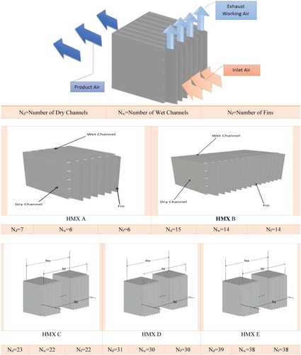
Table 1. Specifications of the parameters used in the experiment.
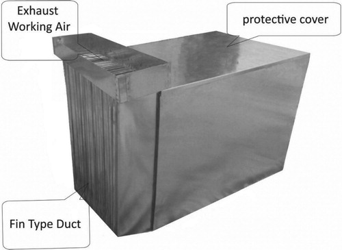
In the present experimental work, the countercurrent arrangement for air is considered for the horizontal regenerative cooling system. For the sake of enhancing the rate and quality of heat and mass transfer between channels, air stream and water flow cross through a thin-film wall plate. In the construction of the exchanger, it should be noted that wall plate of wet and dry channels should be thin enough and made of a high water retention material for wet walls; the dry channel must be made of an impermeable membrane. In order to prevent corrosion, non-corrosion material is used in manufacturing the evaporative cooling system. A water spray system is used at the top of the horizontal configuration of the regenerative evaporative cooling system to saturate evenly all wet channels. To connect the components, moisture resistant glue is applied to the surface. To saturate all wet channels, a distribution system for water is implemented. The components of the regenerative evaporative cooling system are equipped with several dry and wet passages. To create the HMX, some non-metal materials can be employed, while copper and aluminum are the most adequate metals. Here, a thin-film aluminum coated Rayon sheet was selected. The thickness of the aluminum and sheet is 0.3 mm. A fin type duct is used at the end side of the wet channels to guide extracted air to the outside. The fin type duct is made of aluminum and attached with glue to the HMX. The dimensions of the fin type duct are presented in Figure : a height of 400 mm, length of 100 mm and thickness of 0.2 mm. The total channel length, HMX and fin type duct together are 600 mm. The space between the walls is 5 mm. The HMX have 23 dry channels and 22 wet channels with rectangular configuration. A horizontal configuration water feeding system is distributed to supply water over the HMX and saturates all wet vertical channels.
Figure 2. Photographic view of the actual HMX.
3. Experimental
The experimental facility consists of a preconditioning system and a dew-point IEC system. Figure presents the set-up. A frequency inverter is utilized to control flow rate. To increase the temperature of input air, a few electrical heaters are implemented. To control air humidity, water sprays are located after the electrical heater by injecting water fog. To have uniform income of air into the HMX, an air-flow straighter is provided to obtain homogeneity of temperature and relative humidity. By using proper spray, water is distributed over nozzles. Table presents specifications of this HMX.
Figure 3. The schematic diagram of the constructed indirect evaporative experimental set-up.
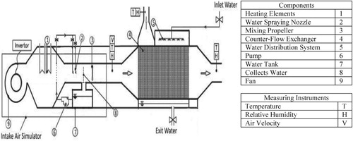
In order to assess and evaluate the thermal performance, data needs to be measured and recorded for a period of days. Relative humidity, air temperature and flow rates of inlet air, relative humidity and air temperature of product flow, and relative humidity and air temperature of working flow should all be measured. All of the measuring devices were calibrated simultaneously against a laboratory standard prior to the tests. The specifications of instruments used are presented in Table .
Table 2. Specification of measuring devices.
4. Numerical analysis
In this work, to understand the behavior of the cooling process through the evaporation cooling system and to simulate flow and energy transfer through the exchanger, numerical simulation is also carried out. To simplify the analysis, assumptions are as below:
Heat transfer between the outer surface of the exchanger and its surroundings is negligible;
The air flows in all wet and dry channels are hydrodynamically and thermally fully developed;
The total properties related to thermophysical properties are assessed at an average temperature;
The process is considered adiabatic and flow is considered incompressible and steady state;
Water was uniformly distributed on the wet channel surfaces;
The channel walls’ thermal resistance can be neglected.
4.1. Differential equations for dry channels
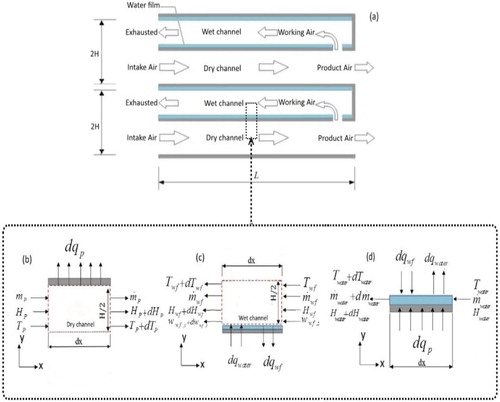
For the control volume of Figure , the energy balance equation is as below:
(1)
(1) where UZ, Twall, TP,
and Hp are overall heat-transfer coefficient (W/m2K), surface or wall Temperature (°C), product air Temperature (°C), product air mass flow rate (kg/s) and product air enthalpy (J/kg), respectively. The total heat transfer coefficient between the water film and intake air is presented as follows:
(2)
(2) where
are product air convective heat transfer coefficient (W/m2 K), thickness (m), wall thermal conductivity (W/m2 K) and convective heat transfer coefficient of water film (W/m2 K) respectively. Air is assumed as an ideal gas, thus enthalpy could be considered as a function of temperature as follows:
(3)
(3) where
is specific heat capacity at defined pressure.
Figure 4. Schematic of the counter-flow regenerative and differential control volumes.
Then, the above-defined equations, Equations (1 and 3), can be re-ordered and written as follows:
(4)
(4) where b is Width of wall (m).
4.2. Differential equations for wet channels
The mass equilibrium for flowing air and water film in wet channels is given by:
(5)
(5) where
denotes the mass flow rate of water film (kg/s),
indicates the mass flow rate of the working air (kg/s), and
represents the humidity ratio of the working air (kgH2O/kgair).
(6)
(6) where σ is surface wettability factor. The convective mass transfer coefficient presented as:
(7)
(7) Le is Lewis number. For the control volume (c), the energy balance equation is given by:
(8)
(8)
(9)
(9)
(10)
(10)
Rearranging Equations (7–9), the following equations are achieved:
(11)
(11) As a result, enthalpy of water vapor could be given as:
(12)
(12) where H0 is latent vaporization heat of water. The enthalpy and specific heat capacity of moist secondary air are as follows (Arora, Citation2000):
(13)
(13)
(14)
(14)
Rearranging Equations (6 and 11–14), the following equations are achieved:
(15)
(15)
(16)
(16)
4.3. Differential equations for water film
The energy balance equation for Figure (d) is given by:
(17)
(17) Rearranging Equations (1, 3, 8 and 17), the following equations are derived:
(18)
(18)
4.4. Performance assessment of a Regenerative Evaporative Cooler
The wet-bulb effectiveness of the Regenerative Evaporative Cooler (REC) is given by Equation (19).
(19)
(19) In a similar way, dew-point effectiveness, εdp, can be mentioned as (Zhao, Li, & Riffat, Citation2008). Tdp is dew-point temperature of air.
(20)
(20)
4.5. Boundary conditions
Dry channel and inlet temperatures are equal (Tdry =Tin at X = L);
The inlet temperature of the duct is equal to the dry channel output temperature (Twet = Tdry at. X = 0);
The humidity of the duct entrance is equal to the humidity of the dry channel output (ωwet = ωdry at x = 0).
5. Validation of numerical method and error analysis
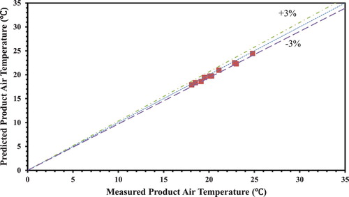
To validate the numerical model, novel layouts of REC have been monitored and the reported results were extracted from Riangvilaikul and Kumar (Citation2010a) and compared with the present outcomes of the numerical and experimental models. This is shown in Figures and . In this work for inlet air, the variation of the temperature and humidity ratio is from 28.25–45.3°C and from 8.6 to 10.9 g/kg, respectively. The criterion for measuring accuracy of the numerical model is considered the outlet cooling air temperature. Numerical results show high accuracy. The most significant error is around ±6%.
Figure 5. Comparison of numerical results with the experimental values of Riangvilaikul and Kumar (Citation2010a) for product air temperature with various inlet air conditions.
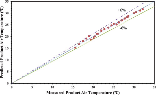
Figure 6. Comparison of numerical results with the present experimental values for product air temperature with various inlet air conditions.
To evaluate the accuracy of the experimental values an uncertainty analysis of instruments is carried out. The method proposed by Moffat (Citation1985) is employed for uncertainty analysis. The uncertainty of temperature, humidity ratio and velocity are calculated and presented as below:
(21)
(21)
(22)
(22)
(23)
(23)
6. Results and discussion
For five cases of HMX, performance is investigated numerically and experimentally. The effects of inlet air conditions (i.e. pressure temperature, velocity and humidity) on the system effectiveness and the outlet air temperature are studied. For air inlet humidity ratios 8.6, 10.9 and 24.1 g/kg, the inlet air temperature’s variation is between 25 and 50°C. Inlet air flow rate is also between 100 and 600 m3/h.
6.1. Influence of inlet air conditions
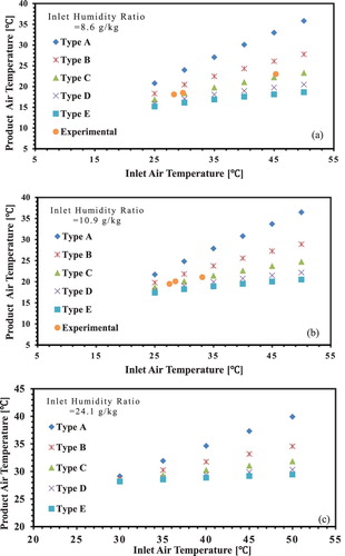
Considering the comfort level of the studied space, product cooling air affects the thermal condition. For different configurations, the product air temperature is depicted in Figure (a–c) versus the variation of inlet air temperature. Inlet humidity ratios are 8.6, 10.9 and 24.1 g/kg. According to Figure , increasing the inlet humidity and raising the inlet air temperature yields an increase in the product air temperature. Among the configurations, HMX E obtains lower product cooling air temperatures, the lowest among the other types. The 20°C and 25°C change of inlet air temperature causes an increase in product air temperature by 44.3% for HMX A, 29.5% for HMX B, 20.5% for HMX C, 14.7% for HMX D and 10.9% for HMX E. If the inlet humidity ratio increases 0.0155 kg/kg, the increase in product air temperature is 15.8% for HMX A, 31.3% for HMX B, 44.5% for HMX C, 54.7% for HMX D and 65.4% for HMX E. Thus, product air temperature variation shows that the water content of inlet moist air is the most significant influencing factor. In addition, the number of channels is another important factor. Increasing the number of channels improves the heat transfer taking place between the channel walls and decreases the product air temperature almost to 13.7% for HMX B, 21.3% for HMX C, 26% for HMX D and 29.2% for HMX E, relative to that of HMX A. For constant inlet air temperature, a decrease in channel number causes an increase in product air temperature; for constant channel number, an increase in inlet air temperature causes an increase in product air temperature. Briefly, cooler performance is noticeably affected by two inlet parameters: humidity and temperature.
Figure 7. Product cooling air temperature for various inlet air conditions.
For various inlet humidity ratios of 8.6, 10.9 and 24.1 g/kg, Figure presents the influence of inlet air temperature on wet-bulb effectiveness. As seen from the figure, wet-bulb effectiveness changes in the range between 51.3 and 57.8% for HMX A, 81.7–88.5% for HMX B, 99.6–104.2% for HMX C, 111.4–115.1 for HMX D and 116.7–122.4% for HMX E. The percentage of increase in wet-bulb effectiveness reaches 56.56% for HMX B, 87.95% for HMX C, 107.24% for HMX D and 119.92% for HMX E, as compared with that of HMX A. The result shows that when the inlet ambient temperature reaches higher temperatures, the wet-bulb effectiveness increases. This increase is due to the greater temperature reduction. A lower air humidity ratio also leads to greater wet-bulb effectiveness. This is because inlet air with a low amount of humidity absorbs moisture from water evaporation better than humid air. Thus for dry air, a more latent heat of evaporation and consequently sensible heat of air delivered more from the dry passage to the wet passage. The result of this heat transfer is a lower temperature of outlet air.
Figure 8. Wet-bulb effectiveness for various inlet air conditions.
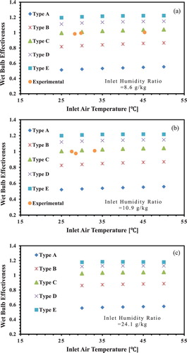
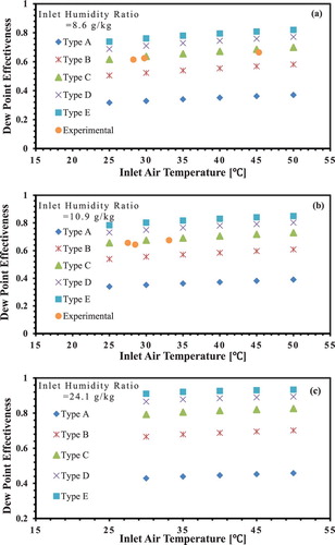
Figure shows the effects of temperature and humidity ratios on dew-point effectiveness. As such systems cool the air to the close of dew-point temperature, dew-point effectiveness is considered a performance measurement criterion. Figure discloses that when temperature and humidity of inlet air increases, a higher dew-point effectiveness is obtained. It also could be seen that the dew-point effectiveness varies between 31.7–45.8% for HMX A, 50.5– 70.2% for HMX B, 61.6–82.6% for HMX C, 68.8–89.4% for HMX D and 73.9–93.4% for HMX E. For the novel REC with finned channels, the percentage of increase in dew-point effectiveness reaches 56.55% for HMX B, 87.95% for HMX C, 107.24% for HMX D and 119.92% for HMX E relative to that of HMX A. Values of dew-point effectiveness can be augmented with the help of increasing inlet air temperature. In a constant humidity ratio, higher inlet air temperature results in higher dew-point effectiveness. Another alluring result is that to achieve the highest dew-point effectiveness at a fixed inlet temperature, the inlet humidity ratio should be increased. This leads to a temperature increase for product air. In general, the higher the effectiveness, the lower the product air temperature. In order to achieve the lowest temperature in the product air, the humidity and the inlet air temperature must be simultaneously decreased.
Figure 9. Dew-point effectiveness for various inlet air conditions.
6.2. Influence of inlet flow rate
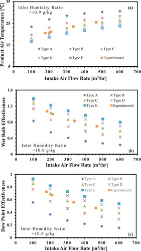
Figure illustrates the variations of the influence of inlet air-flow rates at 33.5°C with a humidity ratio of 10.9 g/kg on (a) product air temperature, (b) dew-point effectiveness and (c) wet-bulb effectiveness based on theoretical and experimental studies. It is clear in Figure that the product air temperature is increased by augmenting the inlet flow rate. For an increase in air inlet flow rates from 100 to 600 m3/h, the product air temperature changes between 23.4 and 30.7°C for HMX A, 19.7–28.3°C for HMX B, 18–26.4°C for HMX C, 17.2–25°C for HMX D and 16.6–23.8°C for HMX E. For the novel REC with finned channels, the percentage of increase in product air temperature reaches to 11.5% for HMX B, 18.6% for HMX C, 23.4% for HMX D and 26.9% for HMX E compared to HMX A. For five configurations, the dew-point effectiveness is illustrated in Figure (b) versus the variation of inlet air flow rate. As dew-point effectiveness decreases, the inlet’s air-flow rate increases. For the novel REC with finned channels, the percentage of increase in wet-bulb effectiveness reaches 67.79% for HMX B, 113.06% for HMX C, 145.72% for HMX D and 170.45% for HMX E relative to that of HMX A. As shown in Figure (c), the dew-point effectiveness is augmented by increasing the inlet air-flow rate. In a novel layout of an indirect evaporative cooler which is equipped with finned channels, the increase in wet-bulb effectiveness reaches 67.77% for HMX B, 113.03% for HMX C, 145.72% for HMX D and 170.43% for HMX E compared to HMX A. To cool an environment by a cooler, it is necessary to have a sufficient air flow rate with a proper temperature. It is found in Figure that product air temperature increases with the air-flow rate. Thus, for the optimum design of HMX, the temperature and flow rate of its product air should first be assessed. According to Figure , an increase in channel number causes the potential of cooling spaces to increase. The result is the variation of cooling performance. However, it could be concluded that to have the same air flow rate, the size and consequently the cost can be decreased.
Figure 10. Effect of inlet air flow rate on (a) product cooling air temperature, (b) wet-bulb effectiveness, and (c) dew-point effectiveness in theoretical and experimental studies.
7. Conclusion
Here, a numerical and experimental investigation was performed for investigating the thermal performance of the novel REC with finned channels in various inlet conditions. The current study investigates in particular the effect of channel number on HMX performance. Experimental values were used in order to validate the proposed numerical model and an acceptable accuracy was recorded. The comparison of the numerical and experimental results has been obtained and well accuracy observed. The experimental works were carried out for five different configurations.
It was observed that with an increase in channel number, the product air temperature decreases about 29.2% for HMX E in comparison to HMX A; however the wet-bulb effectiveness of HMX B, HMX C, HMX D and HMX E are 56.56%, 87.95%, 107.24% and 119.92% more than HMX A. For air-flow rates between 100 and 600 m3/h, the wet-bulb effectiveness for HMX B, HMX C, HMX D and HMX E are 67.79%, 113.06%, 145.72% and 170.45% more than HMX A. In the study, eight cities were selected with various climates. It was observed that a special HMX could be designed for each climate condition that could lead to comfort conditions. Considering the outcome of the current research, it would be interesting to evaluate the influence of channel length on the system’s performance.
Disclosure statement
No potential conflict of interest was reported by the authors.
Related Research Data
References
- Ahmadi, M. H., Ahmadi, M. A., Sadaghiani, M. S., Ghazvini, M., Shahriar, S., & Alhuyi Nazari, M. (2018). Ground source heat pump carbon emissions and ground-source heat pump systems for heating and cooling of buildings: A review. Environmental Progress & Sustainable Energy, 37(4), 1241–1265. doi: 10.1002/ep.12802
- Ahmadi, M. H., Ghazvini, M., Alhuyi Nazari, M., Ahmadi, M. A., Pourfayaz, F., Lorenzini, G., & Ming, T. (2019). Renewable energy harvesting with the application of nanotechnology: A review. International Journal of Energy Research, 43(4), 1387–1410. doi: 10.1002/er.4282
- Ahmadi, M. H., Ghazvini, M., Sadeghzadeh, M., Alhuyi Nazari, M., Kumar, R., Naeimi, A., & Ming, T. (2018). Solar power technology for electricity generation: A critical review. Energy Science & Engineering, 6(5), 340–361. doi: 10.1002/ese3.239
- Akbarian, E., Najafi, B., Jafari, M., Faizollahzadeh Ardabili, S., Shamshirband, S., & Chau, K. (2018). Experimental and computational fluid dynamics-based numerical simulation of using natural gas in a dual-fueled diesel engine. Engineering Applications of Computational Fluid Mechanics, 12(1), 517–534. doi: 10.1080/19942060.2018.1472670
- Arora, C. P. (2000). Refrigeration and air conditioning. New Delhi: Tata McGraw-Hill.
- Bruno, F. (2011). On-site experimental testing of a novel dew point evaporative cooler. Energy and Buildings, 43(12), 3475–3483. doi: 10.1016/j.enbuild.2011.09.013
- Chau, K. W., & Jiang, Y. W. (2002). Three-dimensional pollutant transport model for the Pearl River Estuary. Water Research, 36(8), 2029–2039. doi: 10.1016/S0043-1354(01)00400-6
- Chau, K. W., & Jiang, Y. W. (2004). A three-dimensional pollutant transport model in orthogonal curvilinear and sigma coordinate system for Pearl River estuary. International Journal of Environment and Pollution, 21(2), 188. doi: 10.1504/IJEP.2004.004185
- Chen, Y., Yang, H., & Luo, Y. (2016). Parameter sensitivity analysis of indirect evaporative cooler (IEC) with condensation from primary air. Energy Procedia, 88, 498–504. doi: 10.1016/j.egypro.2016.06.069
- Cuce, P. M., & Riffat, S. (2016). A state of the art review of evaporative cooling systems for building applications. Renewable and Sustainable Energy Reviews, 54, 1240–1249. doi: 10.1016/j.rser.2015.10.066
- Duan, Z., Zhan, C., Zhang, X., Mustafa, M., Zhao, X., Alimohammadisagvand, B., & Hasan, A. (2012). Indirect evaporative cooling: Past, present and future potentials. Renewable and Sustainable Energy Reviews, 16(9), 6823–6850. doi: 10.1016/j.rser.2012.07.007
- Fakhrabadi, F., & Kowsary, F. (2016). Optimal design of a regenerative heat and mass exchanger for indirect evaporative cooling. Applied Thermal Engineering, 102, 1384–1394. doi: 10.1016/j.applthermaleng.2016.03.115
- Hossein Jahangir, M., Ghazvini, M., Pourfayaz, F., & Hossein Ahmadi, M. (2018). A numerical study into effects of intermittent pump operation on thermal storage in unsaturated porous media. Applied Thermal Engineering. doi: 10.1016/J.APPLTHERMALENG.2018.04.023
- Hsu, S. T., Lavan, Z., & Worek, W. M. (1989). Optimization of wet-surface heat exchangers. Energy, 14(11), 757–770. doi: 10.1016/0360-5442(89)90009-1
- Huang, S., Li, W., Lu, J., & Li, Y. (2017). Experimental study on two type of indirect evaporative cooling heat recovery ventilator. Procedia Engineering, 205, 4105–4110. doi: 10.1016/j.proeng.2017.09.910
- Jahangir, M. H., Ghazvini, M., Pourfayaz, F., Ahmadi, M. H., Sharifpur, M., & Meyer, J. P. (2018). Numerical investigation into mutual effects of soil thermal and isothermal properties on heat and moisture transfer in unsaturated soil applied as thermal storage system. Numerical Heat Transfer, Part A: Applications, 73(7), 466–481. doi: 10.1080/10407782.2018.1449518
- Jradi, M., & Riffat, S. (2014). Experimental and numerical investigation of a dew-point cooling system for thermal comfort in buildings. Applied Energy, 132, 524–535. doi: 10.1016/j.apenergy.2014.07.040
- Lee, J., & Lee, D.-Y. (2013). Experimental study of a counter flow regenerative evaporative cooler with finned channels. International Journal of Heat and Mass Transfer, 65, 173–179. doi: 10.1016/j.ijheatmasstransfer.2013.05.069
- Maisotsenko, V., Gillan, L. E., Heaton, T. L., & Gillan, A. D. (2001, September). Method and plate apparatus for dew point evaporative cooler.
- Moffat, R. J. (1985). Using uncertainty analysis in the planning of an experiment. Journal of Fluids Engineering, 107(2), 173. doi: 10.1115/1.3242452
- Mohammadi, A., Ahmadi, M. H., Bidi, M., Ghazvini, M., & Ming, T. (2018). Exergy and economic analyses of replacing feedwater heaters in a Rankine cycle with parabolic trough collectors. Energy Reports, 4, 243–251. doi: 10.1016/j.egyr.2018.03.001
- Moshari, S., & Heidarinejad, G. (2015). Numerical study of regenerative evaporative coolers for sub-wet bulb cooling with cross- and counter-flow configuration. Applied Thermal Engineering, 89, 669–683. doi: 10.1016/j.applthermaleng.2015.06.046
- Pesteei, S., Mashoofi, N., Pourahmad, S., & Roshana, A. (2017). Numerical investigation on the effect of a modified corrugated double tube heat exchanger on heat transfer enhancement and exergy losses. International Journal of Heat and Technology, 35(2), 243–248. doi: 10.18280/ijht.350202
- Porumb, B., Ungureşan, P., Tutunaru, L. F., Şerban, A., & Bălan, M. (2016a). A review of indirect evaporative cooling operating conditions and performances. Energy Procedia, 85, 452–460. doi: 10.1016/j.egypro.2015.12.226
- Porumb, B., Ungureşan, P., Tutunaru, L. F., Şerban, A., & Bălan, M. (2016b). A review of indirect evaporative cooling technology. Energy Procedia, 85, 461–471. doi: 10.1016/j.egypro.2015.12.228
- Ramezanizadeh, M., Alhuyi Nazari, M., Ahmadi, M. H., & Chau, K. (2019). Experimental and numerical analysis of a nanofluidic thermosyphon heat exchanger. Engineering Applications of Computational Fluid Mechanics, 13(1), 40–47. doi: 10.1080/19942060.2018.1518272
- Riangvilaikul, B., & Kumar, S. (2010a). An experimental study of a novel dew point evaporative cooling system. Energy and Buildings, 42(5), 637–644. doi: 10.1016/j.enbuild.2009.10.034
- Riangvilaikul, B., & Kumar, S. (2010b). Numerical study of a novel dew point evaporative cooling system. Energy and Buildings, 42(11), 2241–2250. doi: 10.1016/j.enbuild.2010.07.020
- Tzivanidis, C., Antonopoulos, K. A., & Gioti, F. (2011). Numerical simulation of cooling energy consumption in connection with thermostat operation mode and comfort requirements for the Athens buildings. Applied Energy, 88(8), 2871–2884. doi: 10.1016/j.apenergy.2011.01.050
- Yang, L., Yan, H., & Lam, J. C. (2014). Thermal comfort and building energy consumption implications – A review. Applied Energy, 115, 164–173. doi: 10.1016/j.apenergy.2013.10.062
- Zhao, X., Li, J. M., & Riffat, S. B. (2008). Numerical study of a novel counter-flow heat and mass exchanger for dew point evaporative cooling. Applied Thermal Engineering, 28(14–15), 1942–1951. doi: 10.1016/j.applthermaleng.2007.12.006