
 ?Mathematical formulae have been encoded as MathML and are displayed in this HTML version using MathJax in order to improve their display. Uncheck the box to turn MathJax off. This feature requires Javascript. Click on a formula to zoom.
Abstract
Compressor thermodynamics under varying capacity loads are difficult to predict due to the interaction between the valve-sealing element motion, unloader behavior, and fluid flow. In this paper, a new comprehensive mathematical model of piston compressor under various gas flow loads is established, which is combined with a reciprocating compressor, intake valves, hydraulic plunger cylinder, and unloader, and the model is validated by experimental data. Results show that the installation of finger-type unloaders clearly leads to an increase in flow loss. With a reduction in the flow load of compressed gas, the closing impact velocity of the suction valve plate increases, and the valve appears to oscillate under capacity regulation conditions, leading to premature fatigue damage of the valve component. The optimal combination of design parameters for a suction valve in the capacity regulation system is a 2.7 mm valve lift with a 2100 N/m spring stiffness, yielding a minimum valve resistance loss within admissible valve dynamic motion. The reset spring stiffness of 20 kN/m is chosen as the optimal parameter value by which the impact speed of the suction valve plate at the valve seat is clearly reduced, avoiding excessive impact stress in the reset process.
1. Introduction
Reciprocating compressors are widely used in modern industry, such as in chemical industries, refinery, gas transportation and gas storage (Pichler et al., Citation2016). The compressor is a key component of industrial equipment, and its performance and efficiency directly affect factory production. The compressor valve must often operate in an impure, corrosive environment and undergo 200,000,000 rounds of opening and closing during the compressor overhaul period. Therefore, valve characteristics affect compressor efficiency and reliability more than other components.
Computational approaches for solving engineering problems are important due to their effectiveness and applicability (Ramezanizadeh, Nazari, Ahmadi, & Chauet, Citation2019). Researchers have used different methods to model the thermodynamic process of the piston compressor and valve dynamic characteristics under various operating conditions. These approaches can be classified into global models and differential models where the variable depends on the crank angle (Farzaneh-Gord, Niazmand, Deymi-Dashtebayaz, & Rahbari, Citation2015). To establish appropriate numerical models and obtain accurate computed results, many factors should be considered, such as the computational domain, grid generation, boundary conditions, solver setting, and residual control (Mou, He, Zhao, & Chau, Citation2017).
Mathematical models of different types of compressors under full load conditions have been established by some researchers. Buligan, Paone, Revel, and Tomasini (Citation2002) developed a one-dimensional (1-D) model in which the reed valve was treated as a mass-spring-damper system and the inefficiencies associated with reed valves were estimated. Matos, Deschamps, and Prata (Citation2002, Citation2006) developed a two-dimensional differential methodology to simulate the whole operating cycle of a small refrigeration reciprocating compressor. A mathematical model of a reed-valve reciprocating air compressor was presented by Govindan, Jayaraman, Venkatasamy, and Ramasamy (Citation2009) and Venkatesan, Nagarajan, Seeniraj, and Murugan (Citation2010), and cylinder air pressure variation with cylinder volume and crank angle under varying operating parameters were obtained for validation. The model formation contained thermodynamic equations for the four processes (expansion, compression, suction and discharge processes). Wang, He, Guo, and Peng (Citation2017) used the fluid-structure interaction model to analyze the thermodynamic performance of a refrigerator compressor with reed valves. Akbarian et al. (Citation2018) carried out computational fluid dynamics (CFD) analysis using the dual-fuel mode of an engine to understand the combustion phenomena at partial and full loads. Artificial intelligence or soft computing have been employed more recently in scientific and energy engineering studies (Ardabili et al., Citation2018).
A stepless capacity control method is now being used to implement capacity regulation of a piston compressor to meet fluctuating plant demands for compressor throughput (Jin & Hong, Citation2012). This method for varying compressor capacity allows excess gas to flow back by actively controlling the suction valve motion. Existing products use unloaders actuated by hydraulic pressure to realize delayed closure of the suction valve (Spiegl, Steinrück, & Machu, Citation2008). Compared with the original constant-capacity load condition, valve dynamic characteristics and compressor thermodynamic cycles both change under the capacity regulation condition. A simulation model of a bowtie compressor with novel capacity modulation was developed by Kim and Groll (Citation2007). In their paper, the plate valve was modeled as one-degree-of-freedom mass and spring, and gas flow through the valve port was assumed to be isentropic, compressible, and ideal. Hong, Jin, and Wu (Citation2009) and Tang, Li, and Zhao (Citation2011) analyzed the thermal cycle process of a reciprocating compressor under gas volume regulation. Tang et al. (Citation2013) established equations of different working processes by treating the valves as one hydraulic actuated component. Liu et al. (Citation2014) and Liu, Zhao, Tang, and Li (Citation2016) developed a mathematical model of the adjustment device coupled with inlet valve motion. The dynamic performance of the valve plate and gas pressure in the chamber was tested via simulation.
In the aforementioned studies, a one-degree-of-freedom mass-spring kinetic model was frequently adopted in compressor valve dynamics modeling, and the thermodynamic process of the compressor under capacity regulation condition was presented using a traditional pressure-volume diagram. Most dynamic characteristic studies on the valve have focused on the reed valve; however, plate- and ring-type valves with several flow channels and sealing surfaces are also widely used for piston compressors. Moreover, the finger unloader always fits into seat flow channels, thus reducing the valve equivalent area; however, the influence of the finger unloader on valve performance and efficiency has seldom been investigated.
In this paper, a simulation model is developed to examine the transient thermal-mechanical characteristics of piston compressors under capacity regulation conditions. A multi-sensor experimental system, including dynamic pressure sensors, eddy current displacement sensors, and inductance approach switches, is developed on a 2-D type piston compressor with a stepless capacity regulation device. Theoretical models of valve motion and the thermal cycle are validated by experimental data. The influence of the capacity regulation system on pressure loss and plate-type valve motion is also discussed which is a novelty of the present study. Our findings reveal that valve pressure loss clearly increases in the suction process, and additional pressure loss occurs in the reverse-flow process when the compressor is under capacity regulation conditions. Moreover, the closing impact speed of the valve plate increases as the capacity load declines and the suction valve oscillates, which diminishes the useful life of the compressor valve.
Finally, parameter optimization is performed to identify optimal parameters for the suction valve and capacity regulation system. After optimization, the optimal combination of design parameters for the suction valve of the capacity regulation system is determined as a 2.7 mm valve lift with a 2100 N/m spring stiffness, yielding minimal valve resistance loss within admissible valve dynamic motion. These results are beneficial to the improvement of valve performance and efficiency. Furthermore, the impact speed of the valve plate on the valve seat is clearly reduced, avoiding excessive impact stress in the reset process and prolonging the useful life of compressor valves when unloaders in the capacity regulation system act on compressor valves.
2. Theoretical analysis
2.1. Capacity regulation system with finger unloader
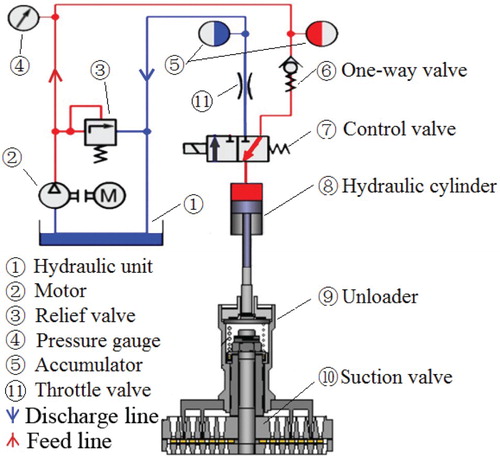
The compressor capacity regulation system is mainly composed of control valves, a hydraulic power unit, hydraulic cylinders, and finger-type unloaders installed on each suction valve, as shown in Figure (Wang, Jiang, Zhang, Zhou, & Liu, Citation2018). Finger unloader 9, which acts on the valve plate of suction valve 10, is actuated by hydraulic cylinder 8. The hydraulic supply line (red line in Figure ) is connected to the plunger-type cylinder 8 via a 2/3-port directional control valve 7, after which the unloader is pushed down. Because of the action of the finger unloader, the closing time of the suction valve plate is delayed, and the subsequent compression stroke then initiates after a certain delay. When the delay time is long enough, plunger-type cylinder 8 is connected to the relief line (blue line in Figure ) due to the change-over of control valve 7, after which the sealing components of the suction valve begin to close. Only the required amount of gas is left in the compression chamber and compressed.
Figure 1. Hydraulic system and the mechanical unloaders.
2.2. Thermodynamic model for compressor under various capacity conditions
The compressor is modeled by a piston cylinder system with several suction valves and discharge valves (Roskosch, Venzik, & Atakan, Citation2017). When compressor capacity is modulated by a regulation system with finger unloaders, the gas flow through valves changes due to the displacement change of suction valves. To investigate the thermodynamic performance of a compressor under various capacity conditions, the transient motion of valves and piston must be analyzed.
2.2.1. Working volume of the cylinder chamber
The instantaneous working volume of the cylinder chamber, which is determined by the transient motion of the piston, varies following the function of the crank angle. It can be expressed as
(1)
(1) where
,
,
and
are the crankshaft radius, cylinder bore, the clearance volume and ratio between the crankshaft radius and connecting rod length, respectively, and
is the crankshaft angle.
The work rate of the piston is calculated as
(2)
(2) where
is the pressure of cylinder gas.
2.2.2. Valve dynamics
In full load condition, the valve-sealing elements of a piston compressor are designed to passively open and close in response to gas force, spring force and deformation force. In partial load condition, an additional driving force acts on the valve-sealing element, which makes the suction valve an active valve. A schema of a plate valve and dynamic forces on the valve-sealing element is shown in Figure . The existence of additional driving force results in changes of valve motion. The dynamics of such a valve under various capacity conditions can be expressed as follows:
(3)
(3) Table presents the dynamic forces acting on the valve-sealing element. By substituting the equations in Table into Equation (3), the general motion characteristic for a suction valve plate can be written as
(4)
(4) where
is the displacement of the suction valve,
is the mass of the suction valve plate,
is the angular velocity
refers to the driving force acting on the valve-sealing element,
and
are two acting coefficients defined to describe the loading time of corresponding forces.
Figure 2. Schema of a plate valve and dynamic forces.
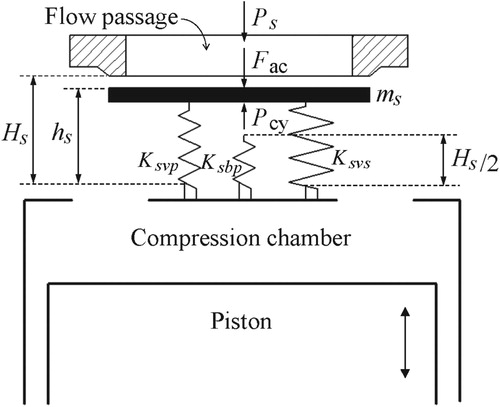
Table 1. Dynamic forces and descriptions of the terms.
The driving force from unloader () acts on the suction valve at a certain time which is determined by the suction valve-opening angle (
). The force is removed when the piston moves to a certain position, determined by capacity load
. The crank angle of unloader force removal (
) can be calculated as
(5)
(5) where
,
and
refer to the expansion volume of gas in the minimum clearance between the cylinder head and the piston, the volume of the compression chamber (also known as the swept volume), and certain gas intake volume, respectively.
When the hydraulic plunger cylinder is connected to the hydraulic relief line, oil flows out of the cylinder and then the unloader is lifted up by the gas pressure and reset spring force. Dynamics of the unloader are given by Equation (6)
(6)
(6) where
,
and
refer to the displacement, mass, and force area of the actuating unloader, respectively;
is the stiffness of the reset spring; and
is the maximum compressed spring length of the reset spring.
2.2.3. Thermodynamic model of compression chamber
The mathematical formulation is based on the continuity and first law of thermodynamics of the compression chamber. The suction and discharge volume are assumed to be infinite in the simulation, and variations in kinetic and potential energies are ignored.
(7)
(7) where
,
, and
denote the heat transfer rate, mass flow rate through suction valves, mass flow rate through discharge valves, and piston work rate, respectively.
and
are the enthalpy of the suction flow and discharge flow, respectively.
is internal energy.
Suction process
From the piston position where suction valves open to the bottom dead center (BDC), gas flows through suction valves from the suction chamber and then into the compression chamber. The mass flow rate through valves is calculated by Equation (8)
(8)
(8) Combining Equations (2), (7), and (8), the pressure inside the cylinder of the compressor in suction stroke is as follows:
(9)
(9) where i is the sequence number assigned to each valve, Ns is the total number of suction valves on one side of the compression chamber,
is the equivalent flow area of each valve,
is the suction pressure,
is the temperature in the suction chamber,
and
refer to the ratio of the specific heat of gas and gas constant, respectively.
Backflow process
From the piston position of BDC to the crank angle of unloader force removal (), the suction valve plate is still held open under capacity regulation conditions. The excess gas that has been sucked into the compression chamber flows out of the chamber and back into the suction chamber through open suction valves. Therefore, the mass backflow rate through suction valves can be calculated using Equation (10)
(10)
(10) By combining Equations (2), (7) and (10), the thermodynamic behavior of the compression chamber in the discharge stroke is as follows:
(11)
(11)
Compression process
After the crank angle , all suction valves return to their original closed position as the piston continues to move. Gas in the sealed chamber is compressed and the pressure increases rapidly, as shown in Equations (12) and (13)
(12)
(12)
(13)
(13) where
is the pressure ratio of cylinder pressure
and suction pressure in the compression process; nc is the adiabatic compression coefficient;
,
and
refer to the expansion volume of gas in the minimum clearance between the cylinder head and piston, the clearance volume of the compression chamber, and certain gas intake volume, respectively.
Discharge process
The discharge valve sealing elements of a piston compressor still passively open and close in response to gas force, spring force, and deformation force under capacity regulation conditions. The general motion characteristics for the discharge valve plate are given by Equations (14) and (15)
(14)
(14)
(15)
(15) where
is the displacement of the discharge valve,
is the mass of the discharge valve plate, and
refers to the pressure ratio of cylinder pressure and discharge pressure. The physical meaning of other terms in the equations are similar to these for suction valves.
Expansion process
When the piston moves back to top dead center (TDC), residual compressed gas remains in the chamber due to a narrow gap between the piston and cylinder head. Then the remaining gas in the clearance chamber starts expanding as indicated in the following equations:
(16)
(16)
(17)
(17) where
is the pressure ratio of cylinder pressure
to discharge pressure in the expansion process, ne is the adiabatic expansion coefficient, and
refers to the clearance volume of the compression chamber.
3. Experimental test system
3.1. Test rig
To investigate compressor performance under various capacity load conditions and to validate the numerical model discussed above, an experimental facility on a 2-D type double-acting compressor with a stepless capacity regulation system was employed. The geometric dimensions and operating parameters of the compressor are listed in Table . As shown in the photograph of the experiment setup (Figure ), the capacity regulation system is composed of three sub-systems: unloaders installed on each suction valve, a hydraulic power unit and a capacity calculation and control system.
Figure 3. Photograph of double-acting piston compressor with stepless capacity regulation system.
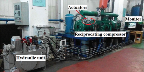
Table 2 Geometric and operation parameters of the compressor
Figure shows acquisition and processing system installed on the compressor for this experimental study.
The data acquisition and processing system was composed of a scope meter, data collector, and data server.
Two proximity switch sensors were fixed to the steel frame, which was positioned close to the free wheel to indicate TDC of the piston position.
Two pressure sensors were used for pressure waveform measurements inside the cylinder.
Figure 4. Positions of measuring points and the experimental test devices.
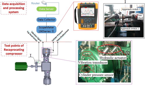
Figure 5. Displacement sensor and installed structure.
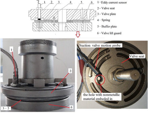
Table 3. Parameters of the proximity switch sensor.
Table 4. Parameters of the piezoelectric pressure sensor.
Table 5. Parameters of the eddy current sensor.
3.2. Experimental procedure
Two sets of experiments were conducted. The first set included testing at 500 rpm compressor speed under a full-capacity load. All channels were kept in synchronization for data collection and pressure waveforms in the compression chamber and suction valve displacement were measured. Conditions of this experiment included a suction pressure of 0.1 MPa, discharge pressure of 0.285 MPa, and test temperature of 25°C. The second set of testing involved eight different capacity loads (20%, 30%, 40%, 50%, 60%, 70%, 80% and 90%) with the capacity adjustment device under the same operating conditions as the first set.
4. Simulation and analysis
To assess the proposed simulation model, numerical and experimental results under working conditions of 0.1 MPa suction pressure, 0.285 MPa discharge pressure, and 500 rpm were compared in the angular domain. The simulation model was validated by comparing measurements and predictions of the major parameters associated with dynamic compressor performance.
4.1. Comparison of measured and predicted results of full load condition
Figures and display plots for the measured and predicted valve displacement and cylinder pressure as a function of the crankshaft angle, obtained in a complete compressor work cycle under full-load condition. In Figure , H1 and H2 represent maximum rebound displacement of the numerical simulation and experimental results, respectively. t1 refers to the calculated duration of the valve-opening process; t2 is the experimental result. t3 and t4 denote the duration of the valve-closing process in the simulation and experiment, respectively. Comparisons of measured and predicted valve displacement for the suction stage appear in Table . As shown in Figure , a rebound phenomenon occurred during opening and closing. The energy of the valve plate was gradually attenuated during impact rebound, and finally the valve plate ultimately remained stationary on the valve lift or valve guard. In the experimental results, several rebound instances during valve opening were due to pressure fluctuations in the actual intake manifold. The results in Figure present the four operating processes under full-load conditions.
Figure 6. Comparison of experimental and predicted results for the suction valve displacement.
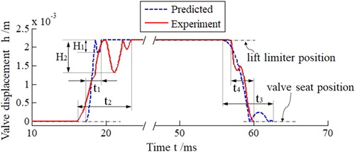
Figure 7. Numerical and measured results for cylinder pressure in a complete work cycle.
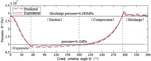
Table 6. Comparison of the measured and predicted valve displacement for suction stage.
To evaluate differences between the predicted and measured results of cylinder pressure, we took the discharge process as an example to introduce the deviation value and absolute error in Figure . The numerical pressure peak value, actual pressure peak value, and maximum deviation value are represented as ,
, and
, respectively.
Figure 8. Sketch of pressure error in discharge process under full load condition.
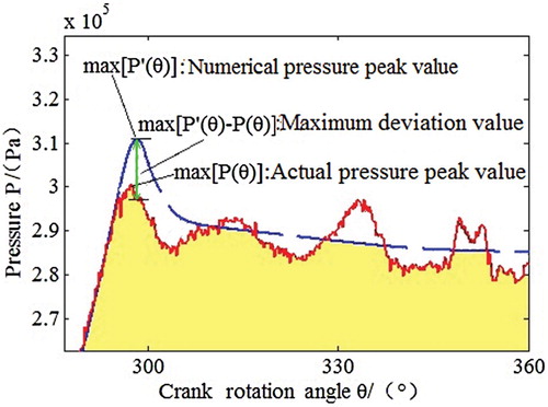
As indicated in Table , the error of the pressure inside the cylinder in the four compressor operating processes ranged from 0.68% to 4.77%, and a better accuracy is obtained in expansion, compression, and discharge processes where the error is within 2%. The maximum deviation value was higher in the suction and discharge processes because of pressure fluctuations in the actual intake and discharge manifold.
Table 7. Deviation values and absolute errors of four compressor operating processes.
The predicted cylinder pressure obtained with the developed model concurred well with the experimental data for the four processes in the entire compressor cycle, confirming that the developed model under full load conditions is acceptable.
4.2. Comparison of measured and predicted results of partial capacity conditions
In addition to the above four processes, a reverse stroke follows after the suction process with suction valves remaining open in the stepless capacity regulation condition. The measured and predicted results for cylinder pressure and the valve displacement during five processes under the 40% load condition are shown in Figure .
Figure 9. Numerical and measured results of valve displacement and cylinder pressure under 40% load condition.
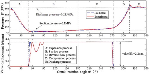
The suction valve was still in the open position as the piston reached the BDC position (180°) and remained open until the crank position of 274°. With reverse piston movement, excess gas flowed out of the compression chamber through the opened valves in an uncompressed state (region C in Figure ). The predicted pressure and valve displacement in Figure are consistent with the experimental data.
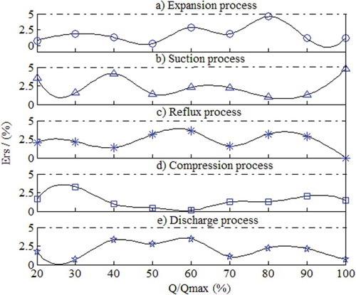
Our experimental results were also compared with those of the numerical model for nine different load conditions (20–100%) to further validate model accuracy. In Figure , the predicted results of cylinder pressure had a total error of less than 5% in all five compressor operating processes under different capacity loads ranging from 20% to 100%. This model maintains a good accuracy under different capacity load conditions, and the simulation model exhibits satisfactory performance in predicting valve dynamics and pressure fluctuations.
Figure 10. Error in five compressor operating processes under different capacity loads ranging from 20% to 100%.
4.3. Analysis of the influence of the capacity regulation system on valve performance
4.3.1. Influence of the capacity adjustment device on flow loss
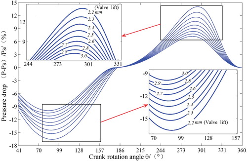
Compared with the original valve without the unloader, the effective flow area of the valve under the capacity regulation condition declined because of finger-type unloader action on the sealing elements of suction valves through the flow channels of valve seats. Figure shows the trends of pressure loss under different capacity loads in the full range of 0–100%. The pressure drop of gas fluid through the valves obviously increased in the suction process and an additional pressure drop occurred during the reverse-flow process when the capacity load was less than 100%. With a reduction in the capacity load, the pressure drop of the suction valve in the reverse-flow process increased as evidenced by the blue curve in Figure .
Figure 11. Pressure loss in both suction process and reverse-flow process under different capacity loads.
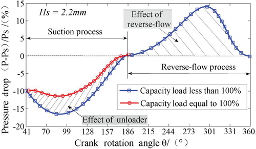
The additional pressure drop across suction valves caused by the capacity regulation system leads to a direct increase in energy loss. To eliminate unnecessary energy loss, an optimized valve design should be identified. Details of this design are discussed in the subsequent section.
4.3.2. Influence of the capacity adjustment device on valve motion
The valve plate was forced into a closed position after the unloader was lifted up at a certain angle set by the capacity regulation system. Closing speeds under different capacities differed as shown in Figure . The closing impact velocity initially increased as the capacity declined and then nearly maintained high values when the capacity was less than 80%. One reason for observing maximum valve speed at a load less than 80% was increased backflow resistance leading to a greater pressure difference between the valve plate. Figure indicates that, when the closing impact speed increased to a certain value, oscillation occurred and the valve plate underwent several rebounds to attenuate energy before it finally remains stationary on the valve lift or valve guard. The closing impact loading during the repeated impact of the valve plate on a valve lift limiter greatly influences on the useful life of an automatic compressor valve.
Figure 12. Closing speed of suction valve under different capacity loads.
As shown in Figure , the closing impact speeds of the plate valve under partial gas flow loads were all larger than that of the original valve without the unloader. From the analysis results, it can be inferred that the operation of the suction valve under part-load condition causes premature fatigue damage of the valve component. This finding mainly explains why the useful life of compressor valves diminish when unloaders in the capacity regulation system act on compressor valves. The closing impact velocity of the valve plate at part-load condition must be limited within a reasonable range. Details on the optimized design of the capacity regulation system are discussed in Section 5.
5. Optimized designs of the capacity adjustment device
As described above, the valve design needs to be improved to reduce the pressure drop caused by the capacity regulation system, and the closing impact velocity of the valve plate must be limited within a reasonable range to avoid excessive impact stress.
5.1. Parameter optimization of valve lift
Variations in pressure drops across the valve against the crank angle for various valve lifts are displayed in Figure . As the valve lift increased, the pressure drop across the suction valve declined; therefore, flow loss caused by the capacity regulation system could be reduced by increasing the valve lift.
Figure 13. Pressure drop vs. crank angle for various valve lifts.
The maximum pressure loss in the suction process and reverse flow process for different valve lifts is listed in Table . As the valve lift increased, the maximum pressure loss in both suction process and reverse flow process declined. In terms of the valve performance, resistance loss should be as small as possible. However, a proper pressure drop through the suction valve was necessary to force the valve to be in an open position in time. A pressure drop of 11.39% in the suction process was a standard value of the original valve without the capacity adjustment device provided by the compressor manufacturer. Therefore, the pressure drop in the suction process could not be lower than the standard value of 11.39%. As revealed in Table , the optimal design for the valve lift of the compressor with the capacity regulation system is 2.7 mm. Compared with the flow loss under the original valve lift of 2.2 mm, pressure loss in the suction and reverse flow processes under optimal lift declined by 4.77% and 5.01%, respectively. The optimal valve lift design hence yields minimum pressure loss within admissible valve performance in the suction process.
Table 8. Maximum pressure loss in suction and reverse flow process at different valve lifts.
5.2. Optimized design of valve spring stiffness
When the valve lift increased from 2.2 mm to 2.7 mm, valve displacement under the original spring stiffness of 1000 N/m was not ideal; as shown in Figure , the valve could not close in a timely manner. To ensure the valve design to be reasonable with respect to valve dynamic motion, the effect of valve spring stiffness was assessed.
Figure 14. Motions of the suction valve at different spring stiffness.
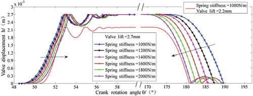
As the spring stiffness increased, open and closed positions of the valve plate approached the required value, as indicated by the arrows in Figure . Comparisons of the time in crank angle degrees of the opening and closing events at different spring stiffnesses are listed in Table . The valve dynamic motion was satisfactory and met the requirements of dynamic design criteria as the stiffness increased to 2100 N/m.
Table 9. Opening and closing angles of valve at different spring stiffnesses.
5.3. Optimized design of reset spring stiffness
The reset spring stiffness of capacity regulation system influenced the reset process of the unloader. By matching the design of the reset spring system of the capacity regulation device, the valve closing velocity could be limited within a reasonable range to avoid excessive impact stress.
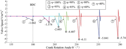
Variations in the valve closing impact speed at different reset spring stiffnesses are shown in Figure . As the reset spring stiffness declined, the valve impact speed continued to decrease for the conditions with a capacity lower than 85%. Under the 90% and 95% capacity conditions, the valve impact speed did not decline until the reset spring stiffness is less than 50 and 30 kN/m, respectively. For all capacity conditions, a desirable impact speed during the valve plate closing period was achieved by reducing the reset spring stiffness. Also, the impact speed could not be lower than the baseline; otherwise, the valve could not close in time resulting in undesirable valve displacement.
Figure 15. Valve closing impact speed vs. reset spring stiffness at various capacities.
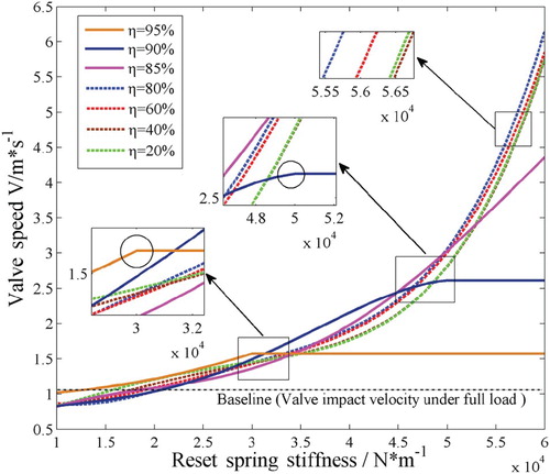
Maximum closing impact speeds of the valve plate at different reset spring stiffnesses are provided in Table . A reset spring stiffness of 20 kN/m was chosen as the optimal parameter value for the capacity regulation system. Compared with the closing impact speeds under the original reset spring stiffness of 60 kN/m, the closing impact speed under the optimal value fell to less than 1.042 m/s. With the aid of the capacity regulation device, lowering the impact speed of the valve plate during closing could be achieved by corresponding optimization of the reset spring parameter.
Table 10. Maximum closing impact speeds of valve plate at different reset spring stiffnesses.
6. Conclusions
This study proposed a comprehensive numerical model of the compressor under various capacity conditions which was validated experimentally to study the capacity regulation transients of compressors and valve dynamic performance. The flow loss of the valve clearly increased in the suction process, and additional flow loss occurred in the reverse-flow process under partial loads. The closing impact speeds of the valve plate increased as the capacity declined, and the suction valve appeared to oscillate, leading to premature fatigue damage of valve component.
The optimal design combination for the compressor valve of the capacity regulation system was found to be a 2.7 mm valve lift with a 2100 N/m spring stiffness, yielding a minimum valve resistance loss within admissible valve dynamic motion. The reset spring stiffness of 20 kN/m was chosen as the optimal parameter value for the capacity adjustment device. After optimization, the impact speed of the valve plate to the valve seat was clearly reduced, avoiding excessive impact stress in the reset process.
In this study, additional relationships between the closing impact speed of the valve plate and capacity load were not yet confirmed, and pressure fluctuations in the intake and discharge manifold were not considered although they may also influence valve efficiency. In future studies, we will aim to improve the method and model to analyze (i) associations between impact speed and capacity load; and (ii) the influences of pressure fluctuations on the intake and discharge manifold on valve efficiency and reliability under different loads.
Acknowledgments
Yao Wang developed the model code and performed the simulations. Yao Wang, Jinjie Zhang and Zhinong Jiang designed the experiments. Yao Wang, Chao Zhou and Wenhua Liu carried them out. Yao Wang prepared the manuscript with contributions from all co-authors.
Disclosure statement
No potential conflict of interest was reported by the authors.
Additional information
Funding
References
- Akbarian, E., Najafi, B., Jafari, M., Ardabili, S. F., Shamshirband, S., & Chau, K. (2018). Experimental and computational fluid dynamics-based numerical simulation of using natural gas in a dual-fueled diesel engine. Engineering Applications of Computational Fluid Mechanics, 12(1), 517–534. doi: 10.1080/19942060.2018.1472670
- Ardabili, S. F., Najafi, B., Shamshirband, S., Bidgoli, B. M., Deo, R. C., & Chau, K. W. (2018). Computational intelligence approach for modeling hydrogen production: A review. Engineering Applications of Computational Fluid Mechanics, 12(1), 438–458. doi: 10.1080/19942060.2018.1452296
- Buligan, G., Paone, N., Revel, G. M., & Tomasini, E. P. (2002, August). Valve lift measurement by optical techniques in compressors. Proceedings of the international compressor engineering conference, Purdue, West Lafayette, USA, Paper No. C13–5.
- Farzaneh-Gord, M., Niazmand, A., Deymi-Dashtebayaz, M., & Rahbari, H. R. (2015). Thermodynamic analysis of natural gas reciprocating compressors based on real and ideal gas models. International Journal of Refrigeration, 56(3), 186–197. doi: 10.1016/j.ijrefrig.2014.11.008
- Govindan, N., Jayaraman, V., Venkatasamy, S. R., & Ramasamy, M. (2009). Mathematical modeling and simulation of a reed valve reciprocating air compressor. Thermal Science, 13, 47–58. doi: 10.2298/TSCI0903047G
- Hong, W., Jin, J., & Wu, R. (2009). Theoretical analysis and realization of stepless capacity regulation for reciprocating compressors. Proceedings of the Institution of Mechanical Engineers, Part E: Journal of Process Mechanical Engineering, 223, 205–213. doi: 10.1243/09544089JPME283
- Jin, J. M., & Hong, W. R. (2012). Valve dynamic and thermal cycle model in stepless capacity regulation for reciprocating compressor. Chinese Journal of Mechanical Engineering, 25, 1151–1160. doi: 10.3901/CJME.2012.06.1151
- Kim, J. H., & Groll, E. A. (2007). Feasibility study of a bowtie compressor with novel capacity modulation. International Journal of Refrigeration, 30(8), 1427–1438. doi: 10.1016/j.ijrefrig.2007.03.006
- Liu, G., Zhao, Y., Tang, B., & Li, L. (2016). Dynamic performance of suction valve in stepless capacity regulation system for large-scale reciprocating compressor. Applied Thermal Engineering, 96, 167–177. doi: 10.1016/j.applthermaleng.2015.11.055
- Liu, G. B., Zhao, Y. Y., Wang, L., Yang, Q., Tang, B., & Li, L. (2014). Dynamic performance of valve in reciprocating compressor used stepless capacity regulation system. Journal of Oral Rehabilitation, 28(1), 26–32.
- Matos, F. F. S., Deschamps, C. J., & Prata, A. T. T. (2002, August). Numerical simulation of the dynamics of reed type valves. Proceedings of the international compressor engineering conference, Purdue, West Lafayette, USA, Paper No. C15–2.
- Matos, F. F. S., Deschamps, C. J., & Prata, A. T. T. (2006, July). A two-dimensional simulation model for reciprocating compressors with automatic valves. Proceedings of the international compressor engineering conference, Purdue, West Lafayette, USA, Paper No. C053.
- Mou, B., He, B. J., Zhao, D. X., & Chau, K. W. (2017). Numerical simulation of the effects of building dimensional variation on wind pressure distribution. Engineering Applications of Computational Fluid Mechanics, 11(1), 293–309. doi: 10.1080/19942060.2017.1281845
- Pichler, K., Lughofer, E., Pichler, M., Buchegger, T., Klement, E. P., & Huschenbett, M. (2016). Fault detection in reciprocating compressor valves under varying load conditions. Mechanical Systems & Signal Processing, 70–71, 104–119. doi: 10.1016/j.ymssp.2015.09.005
- Ramezanizadeh, M., Nazari, M. A., Ahmadi, M. H., & Chauet, K. (2019). Experimental and numerical analysis of a nanofluidic thermosyphon heat Exchanger. Engineering Applications of Computational Fluid Mechanics, 13(1), 40–47. doi: 10.1080/19942060.2018.1518272
- Roskosch, D., Venzik, V., & Atakan, B. (2017). Thermodynamic model for reciprocating compressors with the focus on fluid dependent efficiencies. International Journal of Refrigeration, 84, 104–116. doi: 10.1016/j.ijrefrig.2017.08.011
- Spiegl, B., Steinrück, P., & Machu, G. (2008). U.S. Patent No. 7331767 B2. Washington, DC: U.S. Patent and Trademark Office.
- Tang, B., Li, L. S., & Zhao, Y. Y. (2011 October). Theoretical and experimental study on stepless capacity control system of reciprocating compressor. 7th International conference on compressors and their systems, London, England, paper no. 273–281.
- Tang, B., Zhao, Y. Y., Li, L., Liu, G. B., Wang, L., Yang, Q., … Meng, W. (2013). Thermal performance analysis of reciprocating compressor with stepless capacity control system. Applied Thermal Engineering, 54(2), 380–386. doi: 10.1016/j.applthermaleng.2013.01.036
- Venkatesan, J., Nagarajan, G., Seeniraj, R. V., & Murugan, R. (2010). Experimental validation of a mathematical model of a reed-valve reciprocating air compressor from an automotive-braking system. International Journal of Automotive Technology, 11(3), 317–322. doi: 10.1007/s12239-010-0039-8
- Wang, T., He, Z. L., Guo, J., & Peng, X. Y. (2017). Investigation of the thermodynamic process of the refrigerator compressor based on the m-θ diagram. Energies, 10, 1517. doi: 10.3390/en10101517
- Wang, Y., Jiang, Z. N., Zhang, J. J., Zhou, C., & Liu, W. H. (2018). Performance analysis and optimization of reciprocating compressor with stepless capacity control system under variable load conditions. International Journal of Refrigeration, 94, 174–185. doi: 10.1016/j.ijrefrig.2018.07.013