
 ?Mathematical formulae have been encoded as MathML and are displayed in this HTML version using MathJax in order to improve their display. Uncheck the box to turn MathJax off. This feature requires Javascript. Click on a formula to zoom.
Abstract
The lubrication performance and lubricant volume are of great significance in the design and operating processes for closed mechanical assemblies. A transfer case was taken as the research object, and simulations of flow fields under different working scenarios based on computational fluid dynamics and optimization of lubricant volume were performed. First, a model was proposed based on the volume of fluid method, and the model was validated when good agreement was achieved between simulation and experimental results. Next, the lubrication performances under different lubricant volumes and gear rotation speeds were predicted, and they showed that too much or too little volume of lubricant is undesirable and harmful. Consequently, the optimization of lubrication volume was designed by means of a response surface methodology, and an optimal lubricant volume was configured under a gear speed of 5260 rpm and immersion depth of 2.6 mm, accounting for 66.69% of the total volume.
1. Introduction
Lubrication is critical to closed mechanical assemblies, especially those involving rotating components, such as transfer cases. The performance of the lubricant can influence the engagement of gears, and it directly affects power transfer efficiency (Fietkau & Bertsche, Citation2013; Peric, Nedic, & Trifkovic, Citation2012; Yang, Reddyhoff, & Spikes, Citation2013). Höhn, Michaelis, and Otto (Citation2008) investigated whether a decreased immersion depth of gears can reduce load-independent power losses by using back-to-back gear test rigs. Further studies described the limits concerning the possible reduction of lubricant quantity in gears without a detrimental influence on the load-carrying capacity (Höhn, Michaelis, & Otto, Citation2009). Meng, Liu, Zhang, and Zhang (Citation2012) suggested that a low oil immersion depth is beneficial because of the reduced drag and churning losses of the gears, which, however, result in the detrimental effects of rising gear bulk temperature and increasing gear failure risks. These studies indicated that lubricant volume plays a significant role in the performance of gear lubrication. However, it is a challenge to obtain the appropriate lubricant volume because of various working scenarios and a multiphase oil–air flow state.
A transfer case is a key component for power distribution in modern four-wheel-drive vehicles. It is a gear train whose input shaft is connected to the second shaft of the transmission directly or through a universal joint, and the output shaft is connected to each of the drive axles via a universal joint, the characteristics of which have a considerable influence on the dynamic performance of the vehicle. The mechanical characteristic and control strategies of the transfer case have been the focus of research for many years. An adaptive reconfiguration design system for transfer cases based on the adaptive reconfiguration design theory was constructed, including the modules of the design scheme, adaptable design, and intelligent assembly of the components, and these provide a new method for the design of transfer case component parts (Chen, Citation2015). Asgari and Hrovat (Citation1997) developed a model of an electronically controlled on-demand four-wheel-drive transfer case; it was validated using the available test data. This facilitated the design and evaluation of a suitable control system. Chen, Chen, Wang, Hu, and Huang (Citation2013) analyzed the strength of the transfer case shell; the results can be used as a reference for further optimization. Wang, Wang, and Chen (Citation2015) solved the problem of distortion of the transfer case housing – a problem that could not be solved by traditional design methods – and set up a multiobjective optimal model of the transfer case based on a multiobjective satisfaction method. Panzani et al. (Citation2010) proposed new driveline structures with torque-biasing devices, including an active differential and active transfer case, which contribute to an active-control system that can alter the vehicle behavior by changing the mechanical layout. So far, however, there has been little discussion about the lubrication performance and optimal lubricant volume for transfer cases.
The lubricant in a transfer case undergoes mixing and stirring because of continuous gear rotation, while the gears are affected by the increase or decrease in the force of the oil flow. The computational fluid dynamics (CFD) method has been widely applied as an effective approach to analyze flow fields because of its global accuracy (Akbarian et al., Citation2018; Huang, Su, & Qiu, Citation2015; Mou, He, Zhao, & Chau, Citation2017).
Consequently, although it is known that lubricant volume affects lubrication performance, the optimal lubricant volume for a transfer case is far from being quantified. The aim of the present work is to present a model for predicting lubrication performance from the perspective of the flow field characteristic by means of CFD and to obtain the optimal lubricant volume by using a response surface methodology (RSM) based on the simulation result. In this work, Section 2 generally outlines some numerical theory that might influence accuracy of simulation, and a computational model is presented that involves computational domain, grid arrangement, boundary conditions, and solution control. In the meantime, the model was validated by a designed test rig, and a comparison between numerical model and test results indicates good agreement. The lubrication performance was studied under various conditions, the predictions of flow field characteristics under different lubricant volumes and gear rotation speeds were compared, and the results are presented in Section 3. Furthermore, an optimal lubricant volume was configured by means of RSM based on the simulation results. The main conclusions and discussion are presented in Section 4.
2. Numerical method and computational model
2.1. Numerical method
Because the flow system consists of two incompatible incompressible fluids (air and oil), the volume of fluid (VOF) method was adopted, because it actually keeps and updates the field of the volume fraction of one fluid in each cell instead of the surface height, and it has been widely used to track the interface of two immiscible fluids (Galera, Maire, & Breil, Citation2010; Gao, Morley, & Dhir, Citation2003; Hirt & Nichols, Citation1981; Rabha & Buwa, Citation2010; Rider & Kothe, Citation1998; Zhou, Liu, & Ou, Citation2011). A continuity equation and momentum equation of the oil–air mixture are solved as shown below. Therefore, the two phases have the same pressure and velocity fields.
(1)
(1)
(2)
(2) Here,
is the velocity vector, and ρ is the density of the mixture in the volume cell, which can be calculated as
(3)
(3) where
is the oil volume ratio in the cell, p is pressure,
is the stress tensor, and
contains contributions from body forces.
(4)
(4)
(5)
(5) where I is the unit tensor,
is the gravitational body force, and
is the external body force, which includes model-dependent source terms or user-defined sources.
The renormalization group (RNG) turbulence (Yakhot, Orszag, Thangam, Gatski, & Speziale, Citation1992) was adopted for the present study because it performs well. Furthermore, the RNG
model corrects the turbulence viscosity and improves the
equation so that it is more applicable for describing the turbulent flow inside the transfer case. Furthermore, to model the near-wall region, semiempirical wall functions are used to bridge the viscosity-affected region between the fully developed turbulence region and the wall (Peng, Gui, & Fan, Citation2018). ANSYS FLUENT 14.0 was used in this study, and the governing equations were discretised by the finite-volume method. The second-order upwind scheme was selected for its higher-accuracy computational results to discretise momentum, turbulence dissipation rate, and turbulence kinetic energy, and the time derivative was discretised by the second-order implicit scheme. Furthermore, the pressure implicit with splitting of operators (PISO) algorithm was adopted for the velocity–pressure coupling and solution procedures.
2.2. Model setup and validation
A three-shaft, two-stage transfer case was taken as the research object. The meshing gear model, pairs of helical gears, and hypoid gears with two stages are shown in Figure (a). The gear parameters are listed in Table . Considering that the structure is complex, some simplified operations are performed to reduce resources and shorten the cycle time for the analysis. The simplifications done are as follows. (a) The stiffeners on the surface of the housing are removed. (b) The holes for the seals, bearings, and gasket rings are removed, and it is ensured that the liquids are constrained in the housing. (c) Because empty areas without fluids are not admitted in the VOF flow model, a distance of 2–3 mm exists between the meshing gears; it should be emphasized that too small a distance may lead to meshing failure. Further operations, such as enveloping, cutting, suppressing, and merging, are performed, and the final model with pairs of helical gears and hypoid gears is built, as shown in Figure (b).
Figure 1. Transfer case model.
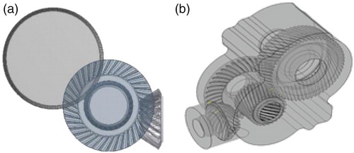
Table 1. Gear parameters.
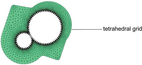
The fluid medium was air having a density of 1.225 kg/m3 and dynamic viscosity of 1.79 *10−5 Pa *s for simulation purposes and a lubricant (SAE 80W/90 oil) having a density of 907 kg/m3 and dynamic viscosity of 0.108 Pa *s for the present study with a working temperature of 293 K. The grid is divided in all areas of the transfer case. Among them, unstructured meshes are used in the gear region, and tetrahedral elements are selected in the remaining regions, as shown in Figure . In this research, an overset mesh (CD-Adapco, Citation2014; Zhang, Zhang, Tezdogan, Xu, & Lai, Citation2018; Zhao, Gao, & Xia, Citation2011) was applied to divide the computational domain with linear interpolation, and a local mesh refinement approach was adopted near the gear boundary to ensure accurate results. The rotational speed of the transfer case gears was applied to the gear domain. The total initial number of cells was 1,078,318. Furthermore, nonslip boundary conditions were adopted, and a spring-based smoothing method was selected to make the cells more adaptive to the boundary rotation and sufficiently smooth. A user-defined function was used to describe the two-phase flow interface; hence, the immersion depth can be expressed as .
Figure 2. Meshed flow field.
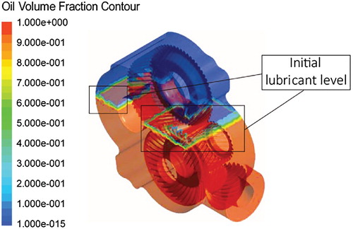
In the following explanation, the reference coordinates (XY-planes) were regarded as the air–liquid interface, and the lubricant depth was referred with respect to the XY-plane. A lubricant level in line with the XY-plane was taken as zero and above the XY-plane was expressed by a positive value. The internal total volume was 2.8196 × 106 mm3, which is equivalent to a lubricant depth of 211.18 mm. The initial lubricant depth was 129.13 mm, corresponding to a lubricant volume of 1.8804 × 106 mm3, as shown in Figure .
Figure 3. Initial oil volume fraction contour.
Experiments were conducted to validate the computational model of the transfer case. Figure shows the components of the transfer case test rig, which consists of two parts: the mechanical transmission and speed control mechanism. The driving motor was a Y132S2-4 three-phase asynchronous motor, and its rated speed was 1440 rpm. The speed was controlled in the range of 0–1440 rpm by a Mitsubishi E700 frequency converter. The experimental modal-transfer case shell (linking to ‘Transfer case’ in Figure ) was made of poly(methyl methacrylate) material with high transparency.
Figure 4. Test rig for transfer case.
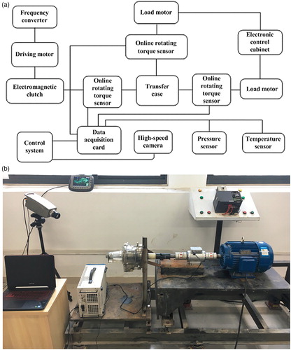
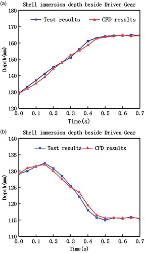
The purpose of the experiment was to observe and analyze the flow characteristics of the lubricant flow field during the gear meshing process. In the experiment, the same initial conditions as in the simulation were set to realize the dynamic process of a lubricant being stirred by gears based on the test rig, and a high-speed camera was used to record the behavior of the internal flow field in real time. Observing the lubricant level measured near the driving gear and driven gear enabled the immersion depths at different moments to be obtained.
Comparing the immersion depth of the simulation and experimental results at the same time, as shown in Figure , demonstrates that the results from simulation are in good agreement with the experimental results, validating the accuracy of the model.
Figure 5. Immersion depths obtained in test and CFD simulation.
3. Numerical results and optimization
3.1. Effect of different gear immersion depths
It is important to optimize the lubricant volume to ensure good lubrication and reduced power losses (Concli, Citation2017). Thus, a series of simulations under different gear immersion depths were conducted. From the simulation analysis, the lubricant velocity and pressure of the flow field can be directly acquired, and they were judged as the parameters of flow field characteristics. Three scenarios were set, in which the rotation speed of the large helical gear was 2500 rpm: Case 1, immersion depth of −49.35 mm; Case 2, zero immersion depth; and Case 3, immersion depth of 49.35 mm.
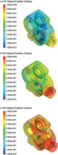
Figures (a–c) show the lubricant volume fraction distributions in Cases 1, 2, and 3, respectively, when the flow fields are stable. The lubricant volume is the least in Case 1, with the lubricant level 79.89 mm distant from the lowest position of the shell. There is no lubricant around the first-stage helical gear, and the helical gears depend entirely on flow mixing and splashing for their lubrication. Figure (a) shows the volume distribution at t = 0.48 s when the flow field is in a steady state, it can be seen that lubricant deficiency exists around the large hypoid gear, which is very unfavorable for lubrication. By observing the volume fraction distributions under the three scenarios, it is clear that the lubricant dispersion phenomenon occurs in the region between the large hypoid gear and the wall. Furthermore, lubricant deficiency exists in Case 1, which proves that this region cannot get satisfactory lubrication. In Cases 2 and 3, the lubricant is stirred evenly, and the lubricant surrounds the meshing area, which conforms to the lubrication requirement.
Figure 6. Lubricant volume fraction under different lubricant depths.
To explore the characteristic accurately, with the consideration of shock of gear engagement, four monitoring points, located at the entry point and exit point of the meshing regions, were set for each pair of gears. The coordinates of each point are listed in Table , and the general positions are represented in Figure (from any point of view, the positions of the four points are obscured by the components, so, here, only a schematic diagram is shown).
Figure 7. Positions of monitoring points.
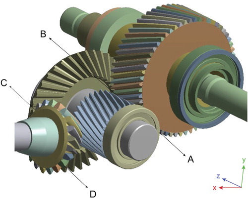
Table 2. Coordinates of monitoring points.
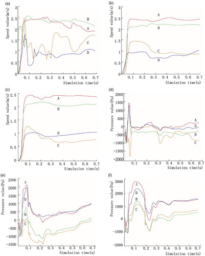
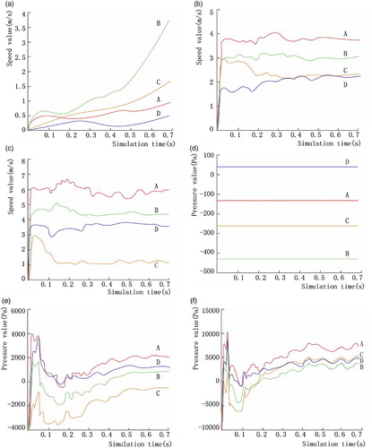
Figure (a–f) shows the velocity and pressure graph at the entry and exit points (A, B, C, and D) in the meshing area. In Figure (a), the lubricant volume is low, causing strong fluctuation in velocity for a long time. However, the lubricant stirring weakens within a short time in Cases 2 and 3. By analyzing Figures (a–c), the following conclusions can be drawn: the speed of points in the meshing area of the helical gear is generally higher than that of the hypoid gear, and it tends to be steady more easily. Figures (d)–(f) show that the exit point in the meshing area is generally in negative pressure when the lubricant volume is large, and the absolute pressure was not negative, which is favorable for lubrication. Therefore, it is advisable to maintain a certain volume of lubricant in the process to prevent severe velocity fluctuation, avoid extra power loss, and maintain good lubrication performance.
Figure 8. Velocity and pressure graph in entry and exit regions under different lubricant depths.
3.2. Effect of different gear speeds
In actual operation, transfer cases work at various gear speeds. With the same lubrication volume, three gear rotation speeds were adopted: 320, 3500, and 5320 rpm. In the process of oil mixing by gear rotation, the oil viscous resistance need to be overcome, and low gear speed cannot give an enough mixing for oil. Therefore, Figure (a) shows that the velocity at the entry and exit points in the meshing region cannot stabilize during the simulation time. Comparison of Figures (b) and (c) with Figure (a) shows that the lubricant flow is steadier and does not change easily under the high-speed condition. From Figures (e) and (f), it can be seen that the pressures at both entry and exit are stable after a short period and that the higher the rotation speed, larger the maximum pressure, and smaller the pressure difference between the entry and exit points. Comparing Figures (e) and (f) shows that the pressure loss at the hypoid gear pair is significantly lower than that at the helical gear pair with the increase of gear speed, as the interference of solid and liquid phase and the interference of gas and liquid phase appear around the helical gear while the lubricant agitation quantity increases under high speeds.
Figure 9. Velocity and pressure graph in the entry and exit regions under different gear rotation speeds.
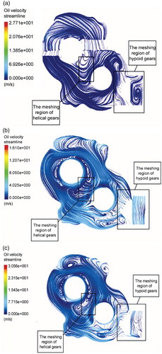
Velocity streamlines at the transverse section in the middle of the transfer case at t = 0.7 s are shown in Figure (a–c), and rotation speeds of 320, 3500, and 5320 rpm. When the gear rotation speed is low, significant stratification appears in the velocity contours, as shown in Figure (a). In the meshing area of the hypoid gears, there is still a vortex at low speed, and a significant lubricant power loss exists at this position. When Figures 0(b) and (c) are compared, one can observe vortices at the same time near the large helical gear and shell body, and this is mainly caused by the interference of the lubricant, structure, and air. All the vortices will affect lubrication performance significantly.
Figure 10. Velocity streamlines at different gear rotation speeds.
3.3. Optimization
To obtain the relative optimal lubricant volume under different gear speeds, a study was conducted in which RSM (Ardabili et al., Citation2018; Li, Liu, Jabbar, & Gao, Citation2004; Wang, Chu, Tao, Jiang, & Zhu, Citation2015) was applied by taking the simulation results as the input based on the computational model.
Considering the immersion depth that decides the lubricant volume as H and the input shaft speed as v, the structural parameter X can be expressed as
(6)
(6) with
(7)
(7) Based on the characteristics of the internal structure of the transfer case and the parameters of the matching vehicle, the interval range of the design variables was determined as follows:
(8)
(8) Here, x1 and x2 are the structural parameters; x1min, and x2min are the minimum values of x1 and x2, respectively; and x1max, x2max are the maximum values of x1 and x2, respectively.
It is hoped that the optimal flow field characteristic and lubrication performance can be obtained with the least time and lubricant volume in the design process. The time t to reach a stable value for flow field and lubricant volume V were involved in the objective function, in which the shortest time and minimum lubricant volume were desired.
(9)
(9)
(10)
(10) Considering the large difference between the two objective functions, the relationship for the unified objective function was established after normalization as follows.
(11)
(11) where tmax represents the longest time to reach a stable value, vmax is the maximum volume in the closed transfer case, and α and β are the weight coefficients, for which a value of 0.5 is assigned.
Lubricant volume and time to reach a stable value under different working scenarios were regarded as the initial data. The factors were various in these scenarios, including lubricant volume (seven groups) and time to reach a stable value (five groups). Based on the range of the design variables, eight groups of basic test points and three sets of test points in a central point were obtained, and a detailed test was conducted. The simulation data are presented in Table . Using a quadratic polynomial, the curve-fitting method was applied to the results, and the specific RSM formula was obtained as
(12)
(12) Based on the range of variables and the RSM optimization calculation, the optimal results were obtained when Fmin was 0.476933. After conversion, this corresponds to a lubricant immersion depth of 2.6 mm and a lubricant volume of 1.904 L, accounting for 66.69% of the total volume. The comprehensive response is shown in Figure .
Figure 11. Comprehensive response.
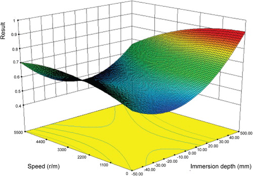
Table 3. Simulation data.
4. Conclusions and discussion
In the current study, a model was proposed for transfer cases considering two-phase flow based on the VOF method. Afterwards, different scenarios were simulated, considering the lubricant immersion depth and gear speed as the independent variables. It was proved that both too much or too little lubricant volume would affect the lubrication performance, and the optimal lubricant volume was obtained, accounting for 66.69% of the total volume. In addition, the helical gear was preferred over the hypoid gear as the driving gear in terms of lubrication performance with the increase of lubricant volume.
An important contribution of this research is presenting a feasible method to predict the lubrication performance and optimize the lubricant volume of closed mechanical assemblies for engineering applications, such as transfer cases. The author apply CFD method to the evaluation and design of lubricating oil quantity of transmission parts. Considering the the traditional mechanical design process has designed the bearing capacity of the gear and the geometry of the shell, therefore, in view of the gear and the geometric shape of the transfer box, the author assumes to meet the working conditions of the transmission parts. Future research is planned to focus on other complex closed mechanical assemblies, such as multiplate electric limited slip differentials, and more-extensive scenarios should be considered, such as temperature. Moreover, some limitations of this research may lie in the following. (1) The prediction error. The data points for optimization that were supported by the simulation results may be a little insufficient because of the limitation of numerical time, and the error that arose was inevitably caused by the shortage of a data-fitting process and the optimization algorithm itself. However, the flow characteristics after optimization were simulated, and this verified that the error was small and not significant enough to affect the optimization results. (2) The absence of experiment. It is desirable to compare simulation and optimized lubrication performances with those obtained from experiments to assess the relative errors. Accordingly, the research shown in this work should agree well with experimental results. (3) The trends of optimal lubrication volume vary with gear speed. The indicators for lubrication performance and how the lubrication performance vary with immersion depth and speed. How does the optimal lubrication volume vary with gear speed? The trends should be shown and supported by more results /plots and provide a guideline.
Acknowledgement
The authors gratefully acknowledge the help provided by Yang Wenchao during the test.
Disclosure statement
No potential conflict of interest was reported by the authors.
Additional information
Funding
References
- Akbarian, E., Najafi, B., Jafari, M., Ardabili, S. F., Shamshirband, S., & Chau, K. W. (2018). Experimental and computational fluid dynamics-based numerical simulation of using natural gas in a dual-fueled diesel engine. Engineering Applications of Computational Fluid Mechanics, 12(1), 517–534. doi: 10.1080/19942060.2018.1472670
- Ardabili, S. F., Najafi, B., Shamshirband, S., Bidgoli, B. M., Deo, R. C., & Chau, K. W. (2018). Computational intelligence approach for modeling hydrogen production: A review. Engineering Applications of Computational Fluid Mechanics, 12(1), 438–458. doi: 10.1080/19942060.2018.1452296
- Asgari, J., & Hrovat, D. (1997, February). On-demand four wheel-drive transfer case modeling. The meeting of the SAE international congress and exposition, Detroit, MI.
- CD-Adapco. (2014). User guide STAR-CCM+ Version 9.0.2.
- Chen, L. Q. (2015). Structural optimisation design and dynamic analysis of key components of four-wheel drive vehicle power distribution (Doctoral dissertation). Retrieved from http://www.wanfangdata.com.cn/details/detail.do?_type=degree&id=Y2925262/thesis/.
- Chen, L. Q., Chen, W. W., Wang, Y. M., Hu, F., & Huang, M. F. (2013). Finite element analysis and modal test of transfer case in intelligent four-wheel drive vehicle. China Mechanical Engineering, 24(16), 2168–2172 +2194.
- Concli, F. (2017). CFD simulation of power losses and lubricant flow in gearboxes. Paper presented at the Agma Fall Technical Meeting.
- Fietkau, P., & Bertsche, B. (2013). Influence of tribological and geometrical parameters on lubrication conditions and noise of gear transmissions. Mechanism and Machine Theory, 69(6), 303–320. doi: 10.1016/j.mechmachtheory.2013.06.007
- Galera, S., Maire, P. H., & Breil, J. (2010). A two-dimensional unstructured cell-centered multi-material ALE scheme using VOF interface reconstruction. Journal of Computational Physics, 229(16), 5755–5787. doi: 10.1016/j.jcp.2010.04.019
- Gao, D., Morley, N. B., & Dhir, V. (2003). Numerical simulation of wavy falling film flow using VOF method. Journal of Computational Physics, 192(2), 624–642. doi: 10.1016/j.jcp.2003.07.013
- Hirt, C. W., & Nichols, B. D. (1981). Volume of fluid (VOF) method for the dynamics of free boundaries. Journal of Computational Physics, 39(1), 201–225. doi: 10.1016/0021-9991(81)90145-5
- Höhn, B. R., Michaelis, K., & Otto, H. P. (2008). Influence of immersion depth of dip lubricated gears on power loss, bulk temperature and scuffing load carrying capacity. International Journal of Mechanics and Materials in Design, 4(2), 145–156. doi: 10.1007/s10999-007-9045-z
- Höhn, B. R., Michaelis, K., & Otto, H. P. (2009). Minimised gear lubrication by a minimum oil/air flow rate. Wear, 266(3–4), 461–467. doi: 10.1016/j.wear.2008.04.037
- Huang, S., Su, X., & Qiu, G. (2015). Transient numerical simulation for solid-liquid flow in a centrifugal pump by DEM-CFD coupling. Engineering Applications of Computational Fluid Mechanics, 9(1), 411–418. doi: 10.1080/19942060.2015.1048619
- Li, J. T., Liu, Z. J., Jabbar, M. A., & Gao, X. K. (2004). Design optimisation for cogging torque minimization using response surface methodology. IEEE Transactions on Magnetics, 40(2), 1176–1179. doi: 10.1109/TMAG.2004.824809
- Meng, Y. G., Liu, Y., Zhang, X. J., & Zhang, Y. M. (2012). Experimental research on reasonable lubricant quantity for transmission gears used in high-speed train. Science China Technological Sciences, 55(12), 3455–3461. doi: 10.1007/s11431-012-4986-3
- Mou, B., He, B.-J., Zhao, D.-X., & Chau, K.-W. (2017). Numerical simulation of the effects of building dimensional variation on wind pressure distribution. Engineering Applications of Computational Fluid Mechanics, 11(1), 293–309. doi: 10.1080/19942060.2017.1281845
- Panzani, G., Corno, M., Tanelli, M., Zappavigna, A., Savaresi, S. M., Fortina, A., & Campo, S. (2010). Designing on-demand four-wheel-drive vehicles via active control of the central transfer case. IEEE Transactions on Intelligent Transportation Systems, 11(4), 931–941. doi: 10.1109/TITS.2010.2055858
- Peng, Q., Gui, L., & Fan, Z. (2018). Numerical and experimental investigation of splashing oil flow in a hypoid gearbox. Engineering Applications of Computational Fluid Mechanics, 12(1), 324–333. doi: 10.1080/19942060.2018.1432506
- Peric, S., Nedic, B., & Trifkovic, D. (2012). An experimental study of the tribological characteristics of engine and gear. Journal of Mechanical Engineering, 59(7), 443–450.
- Rabha, S. S., & Buwa, V. V. (2010). Volume-of-fluid (VOF) simulations of rise of single/multiple bubbles in sheared liquids. Chemical Engineering Science, 65(1), 527–537. doi: 10.1016/j.ces.2009.06.061
- Rider, W. J., & Kothe, D. B. (1998). Reconstructing volume Tracking. Journal of Computational Physics, 141(2), 112–152. doi: 10.1006/jcph.1998.5906
- Wang, G. R., Chu, F., Tao, S. Y., Jiang, L., & Zhu, H. (2015). Optimisation design for throttle valve of managed pressure drilling based on CFD erosion simulation and response surface methodology. Wear, 338–339(5), 114–121. doi: 10.1016/j.wear.2015.06.001
- Wang, Y. M., Wang, Q. D., & Chen, L. Q. (2015). Design scheme selection for transfer case based on multi-objective satisfaction. Journal of Machine Design, 32(12), 68–73.
- Yakhot, V., Orszag, S. A., Thangam, S., Gatski, T. B., & Speziale, C. G. (1992). Development of turbulence models for shear flows by a double expansion technique. Physics of Fluids A: Fluid Dynamics, 4(7), 1510–1520. doi: 10.1063/1.858424
- Yang, S., Reddyhoff, T., & Spikes, H. (2013). Influence of lubricant properties on ARKL temperature rise and transmission efficiency. Tribology Transactions, 56(6), 1119–1136. doi: 10.1080/10402004.2013.804968
- Zhang, S., Zhang, B., Tezdogan, T., Xu, L., & Lai, Y. (2018). Computational fluid dynamics-based hull form optimization using approximation method. Engineering Applications of Computational Fluid Mechanics, 12(1), 74–88. doi: 10.1080/19942060.2017.1343751
- Zhao, F. M., Gao, C. J., & Xia, Q. (2011). Overlap grid research on the application of ship CFD. Journal of Ship Mechanics, 15(4), 332–341. (In Chinese).
- Zhou, L., Liu, D., & Ou, C. (2011). Simulation of flow transients in a water filling pipe containing entrapped air pocket with VOF model. Engineering Applications of Computational Fluid Mechanics, 5(1), 127–140. doi: 10.1080/19942060.2011.11015357