
 ?Mathematical formulae have been encoded as MathML and are displayed in this HTML version using MathJax in order to improve their display. Uncheck the box to turn MathJax off. This feature requires Javascript. Click on a formula to zoom.
ABSTRACT
Distorted inflow caused by the complex structure of the steam generator channel head (SGCH) occurs at the entrance to the reactor coolant pump (RCP) in the AP1000 system, which may generate impeller cracks and result in deterioration of performance and stability. In this paper, to analyze the influence of distorted inflow on flow properties of the RCP, the inflow distortion characteristics are studied by a full three-dimensional steady and unsteady numerical simulation. The simulation model was verified experimentally by testing the RCP with a straight pipe and a channel head at different flow rates. Using this model, the inlet distortion was quantified and the variation law of different distortion was obtained. The results showed that a non-uniform swirling flow under lateral pressure differences was formed when the pump was coupled with a channel head instead of a straight pipe, leading to the destruction of circular symmetry of the inflow field. Further increasing the tube length alone was not effective in improving the inflow field of the RCP, and the inlet swirl effect always existed. As the distorted flow entered the pump with a pair of vortices, the chaotic flow field imposed a non-uniform stress on each blade of the impeller, resulting in the unevenly distributed flow rate of each flow-path of the blade. Then, in the flow channels of the impeller, there were obvious asymmetrical vortex core regions, even in opposite directions, which originally formed in the inflow field of the RCP and raised the risk of blade fatigue failure. Owing to the significant effects of inflow distortion produced by the SGCH, understanding the mechanism of non-uniform inflow characteristic is of great value to the design and optimization of the RCP.
Abbreviations: RCP: reactor coolant pump; SG: steam generator; SGCH: steam generator channel head
1. Introduction
In third generation nuclear power technology, such as AP1000 and CAP1400, the long tube between the reactor coolant pump (RCP) and the steam generator (SG) has been removed. Previously, the RCP hung upside down from the SG (Schulz, Citation2006). Owing to the lack of a sufficiently long transition pipe, the high-temperature and high-pressure fluid flowing out from the SG is poured directly into the RCP. Thus, the flow into the RCP is no longer uniform (as is assumed during design). This makes the inflow of the RCP complicated and chaotic (Jeong, Hwang, Lee, & Chung, Citation2004). The existence of the SG produces the velocity distortion and the vortex, which reshapes the inlet field of each flow path of the impeller. This results in non-uniform loading, vibration and noise.
In terms of pumps and turbines, the impact of distorted inflow on the hydraulic property is not negligible. A numerical simulation was used to study the effect of the wedge angle and leading edge diameter on the performance of the turbine blade under different flow conditions (Sun, Li, & Feng, Citation2012), and the results showed that, because of the existence of the wedge angle and large diameter, the cascade had a fine off-design performance. The influence between the radius and diameter of the elbow and its ability to straighten flow was then investigated (Allen, Werth, & Allaben, Citation2014) and it was found that the non-uniform velocity field caused by its suction elbow may make the pump prone to cavitation. Vagnoli and Verstraete (Citation2015) investigated the influence of elbows on the performance of centrifugal compressors and concluded that the distorted flow inhibited the formation of a rotating stall pattern when the elbow or the bend pipe was mounted in the front of the impeller. As for the inlet effect of the pump, some research on distorted inflow has been reported. Huang et al. (Citation2002) performed an experimental analysis of the SG and obtained the complex velocity field of the SG. They found that axial backflow appeared in the outflow. This resulted in complex outflow conditions and heat conduction. Van Esch (Citation2009) investigated the influence of distorted inflow on the radial load and performance of the pump through experiments. It was found that the head, torque and axial force of the mixed-flow pump decreased when the inflow was non-uniform. Cheng et al. (Citation2014) analyzed the flow field of the SGCH and the RCP as a whole. Their results showed that the head of the RCP was reduced. However, no detailed analysis of the flow field was considered. The external characteristics and cavitation performance of the RCP were simulated by Wang, Wang, Lu, Hou, and Wang (Citation2017). It was observed that the distorted inflow gives rise to a decrease in the head and anti-cavitation performance (Lu, Yang, Wang, & Zhou, Citation2018). Some researchers (Long, Wang, Yin, & Hu, Citation2017; Long, Wang, Yin, Hu, & Ran, Citation2017) simulated and tested the pressure fluctuation characteristics of the RCP. It was found that the distorted inflow led to increases in pressure fluctuation and radial loading of the impeller. The influence of inlet distortion on the hydraulic and hydrodynamic performance of the RCP was analyzed (Hou, Wang, Xu, & Ruan, Citation2016), and the results showed that the influence of the SGCH on the non-uniformity of the inflow, which caused non-uniform loading on each blade, greatly aggravated the fluctuation of both the radial and axial loading (Wang, Wang, Tan, Xu, & Ruan, Citation2018).
Based on the existing literature, the flow field of the SGCH has an influence on the flow field of the outlet pipe, which leads directly to a deteriorated inflow of the connected device.
Experimental investigations have indicated that decreases in the performance, torque and axial forces of the connecting devices, such as the compressor (Engeda, Kim, Aungier, & Direnzi, Citation2003) and pump (Li & Wang, Citation2007), were caused by non-uniform inflow situations. If the connected devices are high-security, high-stability and high-efficiency devices, such as the RCP, the energy losses caused by a non-uniform flow field are extremely large.
In view of the above investigations into different inflow conditions in rotating machinery, the distorted inflow caused by a complicated upstream structure requires deep interpretation and the variation law of inflow distortion is not clear enough. This paper aims to investigate the inflow distortion characteristics of the RCP with a steam generator channel head (SGCH) in the AP1000 system. The axial velocity distribution of the inflow field is obtained and analyzed. For more in-depth analysis, the velocity and swirl characteristics of the flow field are studied by numerical simulation. The inflow field and the impact of different inflows on the performance of the RCP are investigated in detail. Finally, the inflow distortion is quantified, and the vortex structure identified by the regularized helicity method is presented to interpret the mechanism of inflow distortion.
2. Computational method and experimental system
2.1. Experimental set-up
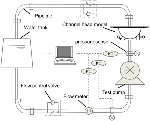
A test rig is built to obtain the distribution of the axial velocity at the inlet and the overall characteristics of the scaled pump. The actual set-up is shown in Figure and a schematic of the experimental set-up is shown in Figure . Tests are performed at room temperature. The fluid medium is water and heat exchange is not considered.
Figure 1. Test set-up.
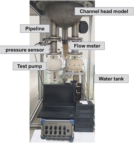
Figure 2. Schematic of the test set-up.
2.2. The model pump
In common with the prototype pump, the model pump is equipped with a diffuser in the spherical shell. There are two outlet tubes on the cold side of the SG. Since the cold side of the SG is symmetrical, the internal flow field is also considered to be symmetrical on account of the symmetry of two outlet tubes on the cold side. Therefore, the SGCH was divided into two mirror portions. The structure of the model pump to be tested and the SGCH are shown in Figure . The impeller parameters are listed in Table .
Figure 3. Geometric model (right) and grids (left).
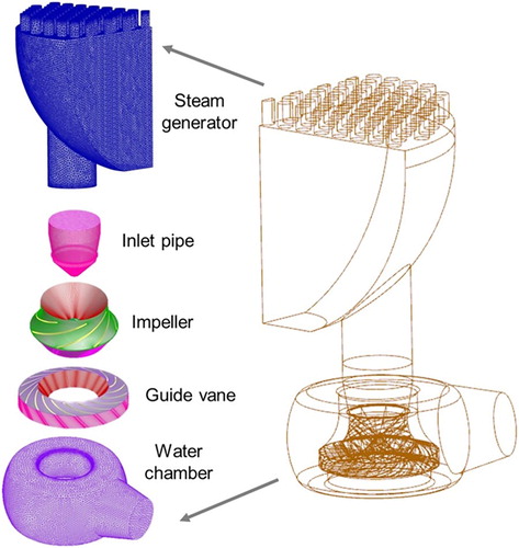
Table 1. Geometric parameters of the impeller.
2.3. Modeling and simulation procedure
Owing to experimental conditions and limited funds, it is only possible to obtain the axial velocity of a limited number of points on the observation section. Numerical simulations are performed to supplement the experimental data and to study the characteristics of the inflow field further.
The geometric model and fluid domains are created by NX 9.0 and discretized using the tetrahedra and hexahedra grid with strong adaptability (Figure ). Grid generation is performed by ANSYS ICEM and the mesh is refined in the near-wall region to ensure accuracy. The grid dependency (Mou, He, Zhao, & Chau, Citation2017) is verified. When the element number is more than 6 million, the pump pressure difference is less than 1%, as shown in Figure . The computational fluid dynamics (CFD) software FLUENT is used to carry out the numerical simulation and the Reynolds-averaged Navier–Stokes equations (Mohammad Ghalandari, Koohshahi, Mohamadian, Shamshirband, & Chau, Citation2019) with the renormalization group k-ϵ turbulence model are chosen. For steady-state calculations, the interface uses the multiple reference frame coordinate system model. For transient calculation, the interface uses the slip mesh model. The y+ (dimensionless wall distance) around the blade is less than 200. The rotating speed of the impeller is set to be 1800 r/min. Each rotation of the impeller is divided into 360 time-steps, i.e. one degree per step. In the numerical calculation process, by monitoring the change in the fluid pressure per unit mass of the pump outlet, it is judged whether the calculation converges. When the monitored pressure remains constant or fluctuates within a small range, the flow field is considered to be stable and the calculation converges. The convergence accuracy is set to 10−5. The simulated boundary conditions are shown in Table .
Figure 4. Grid independence.
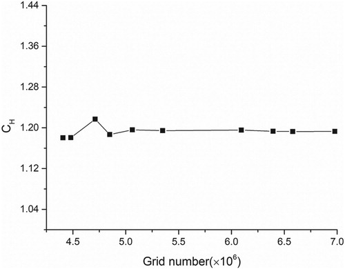
Table 2. Boundary conditions of the simulation.
2.4. Test verification
To verify the accuracy of the CFD numerical calculation, a characteristic experiment was performed using the scaled pump and the results were compared with simulation under the same conditions. The hydraulic performance test device includes the pipeline, flow meter, water tank, test pump and channel head, control system and valves (Figure ).
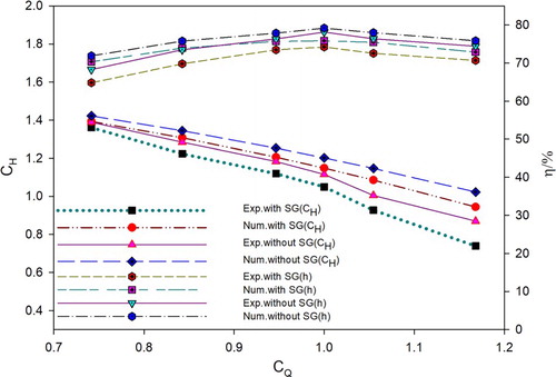
The RCP performance tests were run under 0.7–1.2 times nominal flow rate. During the test, different operating flow states were achieved through regulating valves, and the electromagnetic flow meter (error 0.5%) was used to monitor the flow rate on the line of the pump outlet. The pressure was monitored by a pressure sensor (error 0.1%) which was mounted at the inlet and outlet to obtain the head of the RCP under different flow conditions. To prove the validity of the model, in the same conditions, the numerical calculation results of the test pump were compared with the test results. Previous numerical research (Wang et al., Citation2018) showed that the inflow distortion caused by SGCH, which has a tangential velocity and makes the inflow and the blade constitute a larger angle of attack, leading to an impact loss, results in a decrease on the head of the RCP, and this is consistent with the test results. The difference between the simulation and the test is a result of the measurement error of the equipment during the actual test, as well as the resistance generated by the installation, pipe resistance, mechanical loss, volume loss, and so on; therefore, there is an error in the simulation and test and the numerical calculation is naturally greater than the test result. The characteristic curve (Figure ) shows that the error between the numerical simulation and the experiment is less than 8%, which demonstrates that the engineering application requirement of the model was satisfied.
Figure 5. Comparison of the axial velocity between experiment (Exp.) and simulation (Num.) at the same section. SG = steam generator.
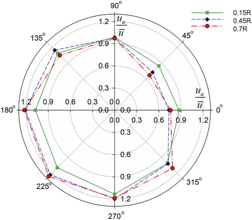
The axial velocity profile of the section during normal flow (1.0Q) was then measured. According to the design, eight measuring points were evenly arranged on the cross-section. The flow rate was adjusted to a predetermined value by controlling the opening of the throttle valve. After the flow field had stabilized, the flow rate was measured by the pitot tube, which has an uncertainty of less than ±0.5%. The flow rate was measured using a magnetic flow meter with an uncertainty of less than ±0.5%. The pressure sensor was used to measure the pressure at the inlet and outlet of the test pump, and the uncertainty was within ±0.1%. The axial velocity distribution at different radii (0.15R, 0.45R and 0.70R) at the standard flow rate (1.0Q) was measured at the same section. The measured position was twice the diameter of impeller inlet diameter (2D) from the bottom of the SG. Figure shows a clear distortion of the velocity of the flow field at the inlet cross-section. This proved that the complicated structure of the SGCH led to distorted inflow and an obvious low-velocity zone formed at the inlet cross-section. With increasing radii, the axial velocity value increased and the velocity distortion became more evident.
Figure 6. Axial velocity for different radii (R) at the 2.0D outlet cross-section.
3. Results and discussion
3.1. Non-uniform distribution at the inlet of the RCP
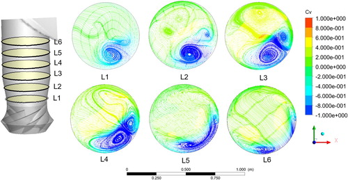
The axial velocity distribution contour at the inlet of the RCP is shown in Figure . There is an obvious low-speed backflow zone in the near-wall area at the exit section. With the increase in length of the inlet pipe, the velocity distribution tends to be similar and the overall velocity tends to be uniform. However, the eccentricity of the velocity distribution always exists within a limited length. It is clear that the distribution of pressure at the pump inlet is highly uneven, as shown in Figure . Also, there is a near-wall low-pressure zone which is nearly the same as the low-speed backflow zone. As the length of the inlet pipe increases, the pressure distribution tends to be similar and the pressure distribution tends to be uniform. Nevertheless, there is always such an eccentric phenomenon within a limited length. It can also be observed that a pair of vortices forms at the beginning and the two vortices in a vortex pair have opposite directions (Figure ). As the length of the inlet pipe increases, the vortices in the low-velocity zone initially expand and then gradually decrease. However, there are always non-uniformly distributed vortices at the pump inlet.
Figure 7. Axial velocity distribution at the inlet of the reactor coolant pump.
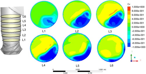
Figure 8. Pressure distribution at the inlet of the reactor coolant pump.
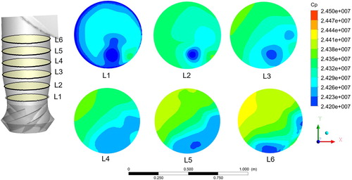
Figure 9. Swirl diagram at the inlet of the reactor coolant pump.
3.2. Flow characteristics at the inlet of the RCP
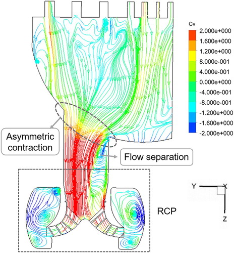
This section quantitatively describes the distortion characteristics to better understand the inflow field. As a result of the asymmetrical abrupt-contraction structure of the SG, the flow path contracts suddenly, which means that the cross-section of the passage decreases abruptly (Figure ). Flow separation occurs near the center of the SG, which leads to the inlet distortion. Backflow also occurs near here.
Figure 10. Streamline diagram of the steam generator. RCP = reactor coolant pump.
To quantitatively describe the velocity distortion, the velocity distribution of the flow field is characterized by the axial velocity distortion (Bulten, Citation2006) and the average drift angle (Zhu & Shouqi, Citation2006). The axial velocity distortion is the ratio of the variance of the axial velocity to the mean value. It reflects the degree to which the axial velocity deviates from the average value (Equation 1). The average drift angle reflects the average value of the angle between the absolute velocity and the outflow cross-section (Equation 2).
(1)
(1)
(2)
(2) where nη is the axial velocity distortion, A is the cross-sectional area, u is the velocity,
is the average velocity, nθ is the average drift angle, ua is the axial velocity, ut is the tangential velocity, and ur is the radial velocity.
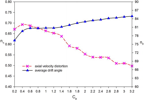
The result (Figure ) shows that, after the fluid flows out from the SG, the velocity distribution becomes gradually uniform as the flow develops. However, the average drift angle decreases initially and then increases as the flow develops. The curve of the average drift angle shows that relying on the method of increasing the length of the pipe cannot effectively improve the inflow field.
Figure 11. Velocity distortion.
To quantify the vortex distortion (Sheoran, Bouldin, & Krishnan, Citation2010), the vortex distortion intensity is described and the related parameters of the vortex characteristics are calculated. The vortex distortion distributions of different cross-sections are extracted along the outflow direction. The attenuation of the vortex distortions along the outflow direction is analyzed.
(3)
(3) where α is the angle, ua is the axial velocity, uθ is the circumferential velocity, and nr is the vortex distortion intensity.
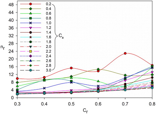
Calculations (Figure ) showed that after the fluid flows from the SG to the pump, the vortex distortion of the fluid appears. At the beginning, the characteristics of irregular and disorder of the vortex distortion intensity on each circle line are presented, and then a stable proportional relationship with the increase in radial length coefficient Cr on the vortex distortion intensity is shown. As the fluid continues to flow into the pump, there is a high vortex area. Finally, the vortex still exists, but the distortion intensity has gradually decreased.
Figure 12. Vortex distortion.
From the above analysis, the SGCH exit flow field is very confusing when axial length coefficient Caaaaa 1.4 and then tends to stabilize gradually. Before Ca > 2.8, there is still a high vortex zone. Thus, if the SG and RCP are directly connected, the length of the short outlet tube of the SGCH connected to the RCP is preferably greater than three times the tube diameter. This ensures that the distorted inflow has a minimal impact on the flow field of subsequent connecting devices. However, the eccentricity of the flow field does not disappear and the average drift angle shows a trend of decreasing first and then increasing. The method of increasing the length of the tube is ineffective for obtaining a uniform flow field. As the fluid flows, the swirl intensity of the flow field decreases. However, it always persists, which has an inlet swirl effect on the subsequent connecting device.
3.3. Effect of non-uniform inflow field distribution
The regularized helicity (Hn) method (Degani, Seginer, & Levy, Citation1990) is used here to analyze the flow characteristics of the inlet vortex structure of the RCP (Xu, Citation2004; Zhang, Citation2011). Under the operating conditions, the impeller of the RCP rotates to work on the fluid, the velocity in the impeller flow passage gradually increases and the speed on the outside of the impeller reaches the maximum. At the inlet of the RCP, inflow distortion, which is caused by the complex structure of the SG, forms several distinct vortex core regions with different directions of rotation (Figure ). After the fluid enters the impeller, the rotating fluid is divided into several parts by blades. In the distorted inflow condition, the incoming flow flows into each channel of the impeller at a different velocity, making the inflow velocity of each blade passage different. Then, vortex core regions, which formed at the inlet of the RCP, begin to function and lead to different flow field distributions of the vortex structures in each blade passage. This is different from the uniform inflow, where the flow field was evenly distributed owing to the symmetry of the inflow field in each channel of the impeller being relatively uniform (Figure ).
Figure 13. Regularization helicity distribution of the uniform inflow field.
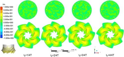
Figure 14. Regularization helicity distribution of the non-uniform inflow field.
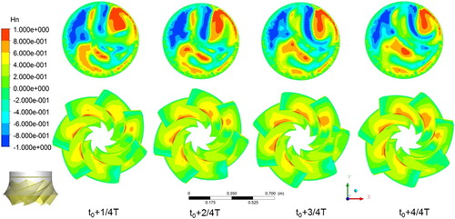
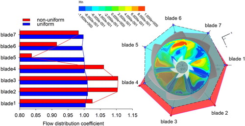
In the case of distorted inflow, the inlet vortex structure, which is produced by the SG, results in distorted velocity distribution at the inlet of the RCP, and the flow distribution of impellers in each passage is no longer uniform, as shown in Figure . As this differs from uniform inflow, the pump design assumption of uniform inflow is not valid. From the perspective of momentum, this imbalance will result in different momentums of fluids in different flow channels. In some parts of the flow passages of the impeller, the velocity and pressure of the fluid at the outlet side increase, while the velocity and pressure of the liquid in the remaining flow passages of the impeller are relatively small; that is, the flow passages are unevenly loaded. This increases the force load fluctuation of the impeller. In general, this distorted inflow leads to the different momentum of fluid in different impeller passages, which means different loading in different passages. Therefore, the symmetrical flow pattern of each flow channel in the impeller is destroyed, which leads to an increase in the load fluctuation and a decrease in stability.
Figure 15. Blade passage flow distribution of the impeller of the reactor coolant pump.
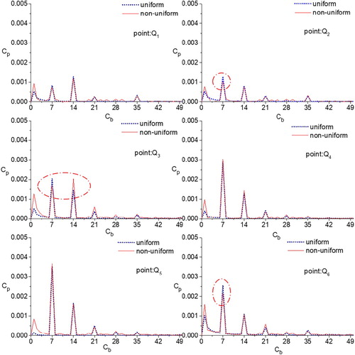
The pressure pulsations with uniform and non-uniform inflow are also analyzed. The distribution of pressure pulsation monitoring points in the calculation domain is shown in Figure . The monitoring points A–G are located at the impeller inlet, the monitoring points P1–P6 are located at the impeller outlet and the monitoring points Q1–Q6 are located at the guide vane. In Figure , points A–G are taken as an example to illustrate the distribution of the monitoring points evenly in the circumferential direction. It is indicated that the pressure pulsation amplitude from the impeller inlet to the vane first increases and then decreases (Figures –), which is similar to the results in the research literature (Ni, Yang, Gao, Zhang, & Li, Citation2016). The distribution characteristics of pressure pulsation frequency in both uniform and non-uniform inflow conditions are basically similar, the only difference being the magnitude of the amplitude. In the uniform inflow condition, the frequency distribution and amplitude of each blade are substantially the same. However, although the frequency distributions of the leading edge of each blade are similar, the magnitudes of the amplitude are different. As shown in Figure , the pressure fluctuation amplitude of monitoring point B is significantly increased, but the pressure fluctuation amplitudes of monitoring points D and E are obviously reduced. This indicates that in the case of non-uniform inflow, the impeller blades are subject to a fixed periodicity load fluctuation during rotation. This may lead to enhanced vibration of the impeller, which greatly reduces the safety and stability of the impeller.
Figure 16. Distribution of monitoring points.
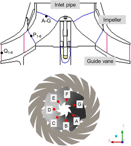
Figure 17. Pressure pulsation distribution of the impeller leading edge.
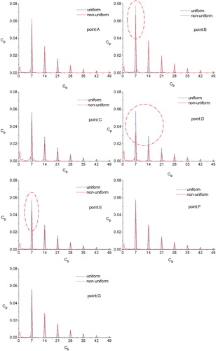
Figure 18. Pressure pulsation distribution of the impeller outlet.
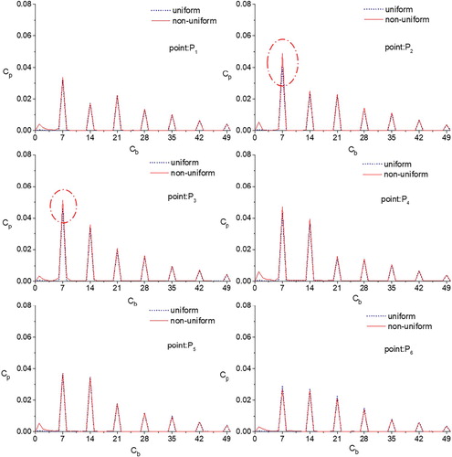
Figure 19. Pressure pulsation distribution of the guide vane outlet.
Thus, is concluded that inflow distortion has a harmful influence on the RCP, and it not only breaks the symmetrical characteristic of internal flow of the impeller flow channel, but also reduces the stability of the RCP.
3.4. A preliminary solution to make the inlet more uniform
As mentioned in Section 3.3, inflow distortion will have a harmful impact on the hydraulic and hydrodynamic characteristics of the RCP. In view of this, a preliminary design for a rectifying baffle on the inlet pipe part, the structure of which is shown in Figure , is proposed. The rectifying device has three main geometric parameters: height (h), inclination (θ) and rotation angle (β). The optimal scheme was obtained through orthogonal experiments: H = 500 mm, θ = 85° and β = 90°.
Figure 20. Geometric parameters of the rectifying baffle.
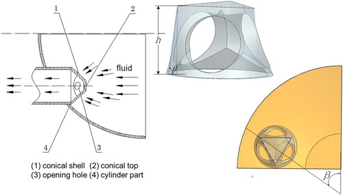
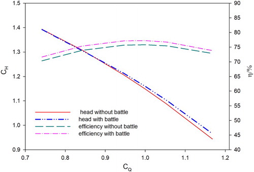
Figure compares the inlet axial velocity before and after adding the rectifying device. It can be seen that the rectifying baffle makes the axial velocity distribution more uniform, and there is no reflux phenomenon. Figure compares the change in hydraulic performance after installing the rectifying baffle on the inlet pipe of the RCP. It can be seen that, compared with the set-up without a baffle, the head and efficiency of the RCP on the design flow rate are not reduced.
Figure 21. Comparison of inlet axial velocity with (left) and without the rectifying baffle (right).
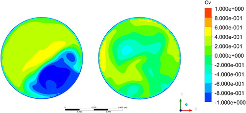
Figure 22. Comparison of head and efficiency with and without the rectifying baffle.
4. Conclusions and limitations
An experimental platform was set up to measure the axial velocity distribution of the inlet of the RCP. The existence of inflow distortion was verified, and the distortion of the inflow quantified with velocity and vortex factors. The principle of the distortion flow at the inlet of the RCP was obtained. Thus, it was concluded that the distortion inflow caused by the SGCH makes the inflow field of the RCP more complex. Increasing the tube length alone is not effective in improving the inflow field and the inlet pre-swirling effect will always exist.
A full three-dimensional steady and unsteady numerical simulation was used to investigate the inlet distortion. By regularized helicity analysis, compared with the uniform inflow, a distinct vortex core region formed at the inlet of the RCP. The flow channels of the impeller produced asymmetrical or even opposite vortex core regions, resulting in uneven distribution of flow in each flow passage, and finally causing uneven loading of the impeller. The symmetrical characteristic of the internal flow of the impeller flow channels was broken, decreasing the stability of the impeller. However, to elucidate the evolutionary process of the vortex, a three-dimensional vortex structure numerical calculation with higher configuration computers and higher accuracy (e.g. direct numerical simulation) is needed, and the evolutionary law of the vortex generated by the distorted inflow could then be analyzed.
A preliminary device (rectifying baffle) was designed to fix the issue and the results show that it made the inlet more uniform and did not reduce the head or efficiency of the RCP. However, further research is needed to find a better solution.
The analysis in this paper did not consider the effect of different rotation speeds on the blades of the RCP. A non-uniform inlet with different inlet pre-swirling caused by different rotation speeds may lead to worse performance for the RCP. Future research will consider this condition. In addition, the non-uniform pressure pulsation of the impeller blades caused by channel head is a kind of periodic load pulsation for blades, which increases the radial force of the RCP, resulting in a concomitant increase in the vibration of the RCP. Furthermore, wetting modal tests under non-uniform inflow in a water environment need to be investigated in a future study to understand the mechanism of the change in hydrodynamic characteristics of the RCP with an SGCH.
Nomenclature
| nη | = | axial velocity distortion (m/s) |
| A | = | cross-sectional area (m2) |
| u | = | velocity (m/s) |
| = | average velocity (m/s) | |
| nθ | = | average drift angle (°) |
| ua | = | axial velocity (m/s) |
| ut | = | tangential velocity (m/s) |
| ur | = | radial velocity (m/s) |
| α | = | angle (°) |
| ua | = | axial velocity (m/s) |
| uθ | = | circumferential velocity (m/s) |
| nr | = | vortex distortion intensity (non-dimensional) |
| Hn | = | regularized helicity (non-dimensional) |
| Q | = | flow rate (m3/h) |
| Qd | = | flow rate in design point (17,886 m3/h) |
| CQ | = | Q/Qd (flow rate coefficient, non-dimensional) |
| La | = | axial length (m) |
| D | = | diameter (m) |
| Ca | = | La/D (axial length coefficient, non-dimensional) |
| Cv | = |
|
| Cp | = |
|
| Fr | = | frequency |
| Frs | = | shaft frequency |
| Cb | = | Fr/Frs (frequency coefficient, non-dimensional) |
| Lr | = | radial length (m) |
| Cr | = | Lr/D (radial length coefficient, non-dimensional) |
| N | = | number of impellers (7) |
| Qb | = | flow rate of flow passage of the impeller (m3/h) |
| Cm | = | Qb/Qd/N (flow distribution coefficient, non- dimensional) |
| H | = | head of pump (m) |
| Hd | = | head of pump in design point (111 m) |
| CH | = | H/Hd (head coefficient) |
| y+ | = | distance from the wall (non-dimensional) |
| D | = | diameter of inlet pipe (m) |
| η | = | efficiency under nominal rate flow (non- dimensional) |
Disclosure statement
No potential conflict of interest was reported by the authors.
Additional information
Funding
References
- Allen, M. E., Werth, D. E., & Allaben, C. C. (2014). Evaluation of reducing elbow characteristics versus velocity distribution at the pump inlet. In World environmental and water resources congress 2014 (pp. 1207–1215). doi: abs/10.1061/9780784413548.121
- Bulten, N. W. H. (2006). Numerical analysis of a waterjet propulsion system (Doctoral dissertation). Retrieved from research.tue.nl/en/publications/numerical-analysis-of-a-waterjet-propulsion-system
- Cheng, H., Li, H., Yin, J., Gu, X., Hu, Y., & Wang, D. (2014). Investigation of the distortion suction flow on the performance of the canned nuclear coolant pump. In 6th International Symposium on Fluid Machinery and Fluid Engineering, ISFMFE 2014 (pp. 166–171). doi: 10.1049/cp.2014.1144
- Degani, D., Seginer, A., & Levy, Y. (1990). Graphical visualization of vortical flows by means of helicity. AIAA Journal, 28(8), 1347–1352. doi: 10.2514/3.25224
- Engeda, A., Kim, Y., Aungier, R., & Direnzi, G. (2003). The inlet flow structure of a centrifugal compressor stage and its influence on the compressor performance. Journal of Fluids Engineering, 125(5), 779–785. doi: 10.1115/1.1601255
- Ghalandari, M., Koohshahi, E. M., Mohamadian, F., Shamshirband, S., & Chau, K. W. (2019). Numerical simulation of nanofluid flow inside a root canal. Engineering Applications of Computational Fluid Mechanics, 13(1), 254–264. doi: 10.1080/19942060.2019.1578696
- Hou, X., Wang, P., Xu, Z., & Ruan, X. (2016). Influence of steam generator channel head on reactor coolant pump inflow field. Journal of Drainage and Irrigation Machinery Engineering, 34(4), 277–282. doi: 10.3969/j.issn.1674-8530.15.0207
- Huang, W., Zhang, W. Q., Tao, W. Q., He, J. S., Huang, H., Zhang, F. Y., & Liu, X. B. (2002). Flow characteristics experimental study within connection between steam generator channel head and pump suction. Nuclear Power Engineering, 23(2; SUPP), 38–42. doi: 10.1007/s11630-008-0314-1
- Jeong, J. J., Hwang, M., Lee, Y. J., & Chung, B. D. (2004). Non-uniform flow distribution in the steam generator U-tubes of a pressurized water reactor plant during single- and two-phase natural circulations. Nuclear Engineering and Design, 231(3), 303–314. doi: 10.1016/j.nucengdes.2004.02.002
- Li, Y. J., & Wang, F. J. (2007). Numerical investigation of performance of an axial-flow pump with inducer. Journal of Hydrodynamics, Ser. B, 19(6), 705–711. doi: 10.1016/S1001-6058(08)60007-4
- Long, Y., Wang, D., Yin, J., Hu, Y., & Ran, H. (2017). Numerical investigation on the unsteady characteristics of reactor coolant pumps with non-uniform inflow. Nuclear Engineering and Design, 320, 65–76. doi: 10.1016/j.nucengdes.2017.04.027
- Long, Y., Wang, D., Yin, J., & Hu, Y. (2017). Experimental investigation on the unsteady pressure pulsation of reactor coolant pumps with non-uniform inflow. Annals of Nuclear Energy, 110, 501–510. doi: 10.1016/j.anucene.2017.07.010
- Lu, Y., Yang, J., Wang, X., & Zhou, F. (2018). A symmetrical-nonuniform angular repartition strategy for the vane blades to improve the energy conversion ability of the coolant pump in the pressurized water reactor. Nuclear Engineering and Design, 337, 245–260. doi: 10.1016/j.nucengdes.2018.07.007
- Mou, B., He, B. J., Zhao, D. X., & Chau, K.-w. (2017). Numerical simulation of the effects of building dimensional variation on wind pressure distribution. Engineering Applications of Computational Fluid Mechanics, 11(1), 293–309. doi: 10.1080/19942060.2017.1281845
- Ni, D., Yang, M., Gao, B., Zhang, N., & Li, Z. (2016). Flow unsteadiness and pressure pulsations in a nuclear reactor coolant pump. Strojniski Vestnik/Journal of Mechanical Engineering, 62(4), 231–242. doi: 10.5545/sv-jme.2015.3192
- Schulz, T. L. (2006). Westinghouse AP1000 advanced passive plant. Nuclear Engineering and Design, 236(14–16), 1547–1557. doi: 10.1016/j.nucengdes.2006.03.049
- Sheoran, Y., Bouldin, B., & Krishnan, P. M. (2010, October). Compressor performance and operability in swirl distortion. In ASME Turbo Expo 2010: Power for Land, Sea, and Air (pp. 2453–2464). American Society of Mechanical Engineers. doi: 10.1115/GT2010-22777
- Sun, H., Li, J., & Feng, Z. (2012). Investigations on aerodynamic performance of turbine cascade at different flow conditions. Engineering Applications of Computational Fluid Mechanics, 6(2), 214–223. doi: 10.1080/19942060.2012.11015416
- Vagnoli, S., & Verstraete, T. (2015). URANS analysis of the effect of realistic inlet distortions on the stall inception of a centrifugal compressor. Computers & Fluids, 116, 192–204. doi: 10.1016/j.compfluid.2015.03.015
- Van Esch, B. P. M. (2009). Performance and radial loading of a mixed-flow pump under non-uniform suction flow. Journal of Fluids Engineering, 131(5), 051101. doi:10.1115/1.3089539.051101 doi: 10.1115/1.3089539
- Wang, W., Wang, Y., Lu, S., Hou, T., & Wang, X. (2017). Research on effects of non-uniform suction flow on performance in reactor coolant pump. Journal of Dalian University of Technology, 57(5), 453–458. doi: 10.7511/dllgxb201705003
- Wang, Y., Wang, P., Tan, X., Xu, Z., & Ruan, X. (2018). Research on the non-uniform inflow characteristics of the canned nuclear coolant pump. Annals of Nuclear Energy, 115, 423–429. doi: 10.1016/j.anucene.2018.02.007
- Xu, Z. H. (2004). The analysis of three-dimensional flow in high-speed pump and research of its fluid-induced pressure fluctuation (Doctoral dissertation). Retrieved from http://cdmd.cnki.com.cn/article/cdmd-10003-2005036016.htm
- Zhang, X. (2011). Energy conversion characteristics of stainless steel stamping and welding centrifugal pumps and design method (Doctoral dissertation). Retrieved from http://cdmd.cnki.com.cn/Article/CDMD-10299-1011148352.htm
- Zhu, H., & Shouqi, Y. (2006). Optimal design of inlet conduit for technical innovation of large pumping stations. Journal of Hydroelectric Engineering, 25(2), 51–55. doi: 10.3969/j.issn.1003-1243.2006.02.011