
 ?Mathematical formulae have been encoded as MathML and are displayed in this HTML version using MathJax in order to improve their display. Uncheck the box to turn MathJax off. This feature requires Javascript. Click on a formula to zoom.
Abstract
This study aims to provide valuable insight into the irrigation in curved root canals with CFD method. Numerical simulation of the flow originated from a side-vented or an open-ended flat needle located in the prepared root canal with two different insertion depths was performed. The distribution of velocity, wall shear stress, apical pressure, and the detailed flow structures were all evaluated. The results show that both the side port of the side-vented needle and the curved portion of the target root canal tends to make circumferentially non-symmetric wall shear stress distribution and asymmetrical streamlines. However, the impact of the root-canal curvature variation on the flow pattern is apparent only when the open-ended flat needle was selected for irrigation or the needle was inserted into the curved part of the root canal. The insertion depth and the size of the gap between the outer surface of the needle and the root canal internal wall are critical to the apical pressure, except the former is simultaneously crucial for the micro-velocity zone decreasing. Overall, the optimal method for effective irrigation in a curved root canal is the side-vented needle with the same curvature to the root canal, deeper insertion, and reasonable gap size.
Nomenclature
| L | = | The length of the target root canal |
| = | The length of the straight portion of the root canal for irrigation | |
| = | The length of the curved portion of the root canal for irrigation | |
| θ | = | The turning angle of the curved portion of the root canal |
| = | The diameter of the cross-section corresponding to the apical stop of the target root canal | |
| = | The external diameter of the needle | |
| = | The internal diameter of the needle | |
| = | The length of the needle | |
| R | = | The radius curvature |
| = | The spacing between the end of the syringe needle and the apical stop of the target root canal | |
| = | The taper of the whole root-canal | |
| = | The taper of the exterior shape of the curved part of the number V needle | |
| = | The taper of the interior pipe of the curved part of the number V needle | |
| V | = | Velocity |
| = | The irrigant velocity component along the centerline of the root canal | |
| ρ | = | The density of the irrigant |
| μ | = | The dynamic viscosity of the irrigant |
| τ | = | The shear stress on the internal surface of the root canal |
Introduction
A successful root canal therapy requires the elimination of bacterium and smear layer in the root canal system by cleaning and shaping (Dioguardi et al., Citation2018; Rodriguez-Figueroa et al., Citation2014). At present, syringes irrigation by sodium hypochlorite (NaOCl) is still one of the commonest, easiest, and cheapest cleaning methods in clinical practice (Dioguardi et al., Citation2018).
To study the flow of syringe irrigation solutions in the root canal, a variety of methods have been adopted or developed by researchers. Devi and Abbott (Citation2012) studied the flow patterns of the irrigating solutions by visual observation, video, and photographs. Rodriguez-Figueroa et al. (Citation2014) used a spectrophotometric method to evaluate the extrusion of the NaOCl irrigant during root canal irrigation. Another study added a contrast medium to the irrigating solution and observed the flow of the irrigating solution in the root canal by X-ray development (Abou-Rass & Piccinino, Citation1982). However, what should be noticed is that all the methods used in these studies are unable to measure the shear stress. It is thus desirable to find a way to study the flow of irrigating solutions in the root canal more directly. With the development of computer science and numerical methods, computational fluid dynamics (CFD) is dawning and shows great potential.
As a branch of fluid mechanics, CFD analyzes and solves problems such as fluid flow (gas or liquid) by numerical methods and algorithms. It originally limited in industrial and engineering fields but has shown great advantages in biology in recent years, such as the respiratory system (Xu et al., Citation2006; Yang et al., Citation2006) and the cardiovascular system (Arvand et al., Citation2005; Pekkan et al., Citation2005). Certainly, there are also the applications of CFD in the oral cavity, especially in root canal irrigation (Ghalandari, Mirzadeh Koohshahi, et al., Citation2019; Shen et al., Citation2010). Usually, the root canal was modeled as a cone-pipe, which is irrigated by a needle penetration (Shirazi et al., Citation2017). Researchers evaluated the effects of irrigation flow rate (Boutsioukis, Lambrianidis, & Kastrinakis, Citation2009), needle insertion depth and types (Chen et al., Citation2014; Ma et al., Citation2015; Shen et al., Citation2010), canal taper (Boutsioukis, Gogos, et al., Citation2010a, Citation2010b) on root canal irrigation. Besides, the development of the research methods brings more and more studies of some complex root canals in these years (Pereira et al., Citation2018; Wang et al., Citation2015).
Among the complex root canals, the curved root canal is a typical one and accounts for a large proportion in the clinic. Its complicated structure is not only detrimental to the preparation of root canals but also reduces the efficiency of root canal irrigation, because of the difficulty for the needle in penetrating into the apical area. In the previous decade, Gao et al. (Citation2009) investigated irrigation flow in a curved root canal, mainly aiming at finding a suitable CFD method with detailed comparisons of the numerical results and the experimental data. The most important conclusion was that CFD simulation with SST k-ω as the turbulence model is optimal for the numerical investigation of the root canal irrigation. However, the characteristic of the curved structure and its effect has not been considered. Subsequently, two other studies of them (Gao and Shen) about root canal irrigation in curved root canal were performed, which respectively published in 2014 summarizing the knowledge of effective and safe endodontic irrigation (Haapasalo et al., Citation2014) (from the goals, solutions, and equipment for irrigation) and in 2015 assaying the impact of the syringe needle location variation on the irrigation flow pattern in a C-shaped root canal (Wang et al., Citation2015). Another relevant research in 2014 aimed at (Koch et al., Citation2014) measuring a cross-section velocity distribution of the flow field around a polymer rotary finishing file in a root canal. In a summary, according to the related articles published recently, one basic fact can be found that the complex irrigation flow field details in the curved root canal and also the impact of curvature variation on the irrigant extrusion have rarely been studied in detail, no mention to the corresponding irrigation strategy. Though two pieces of research published in 2012 (Malki et al., Citation2012) and 2013 (Psimma et al., Citation2013) are exceptions, deficiencies still exist. The former aimed at the root canal irrigation with ultrasonic oscillating technology, and evaluated the impact of file insertion depth variation on its ability to extrude dentin debris, as well as the effect of inserted depth variation on the flow characteristic of irrigation fluid in the root canal. What's more, both a straight and a series of curved root canals have been selected as study subjects, and then compared in detail. The mechanisms of ultrasonic-activated irrigation are completely different from that of needle syringe irrigation. As to the study in 2013 (Psimma et al., Citation2013), though the effects of the type and the insertion depth of the needle used for irrigation as well as the apical preparation size and the curvature of the target root canal on the irrigant removal have been investigated, few conclusion has been obtained from the respect of flow dynamics. A conductivity probe was used for real-time detection of the quantity of the irrigant, which has been extruded from the root canal. What’s more, there are no detailed interprets from the view of flow field structures. Also, there was no corresponding method or suggestions to cope with the problem brought by the curved structures.
Therefore, in this research, flow structures and patterns in a series of root canals with different degrees of curvature was systematically simulated with computational fluid dynamics method, for exploring the influence of the root-canal curvature and its variation on the efficiency of syringe irrigation, and also for providing valuable insight for the syringe irrigation strategy in this kind of curved root canal. As a comparison, the usual straight root canal has also been simulated and analyzed.
Physical model and numerical method
Geometric model and irrigant material
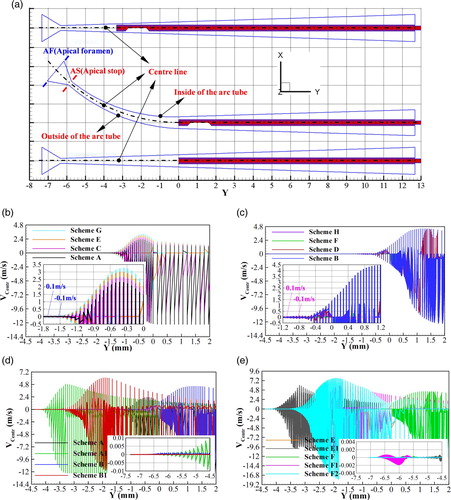
Both the curved root canal and the rear apical anatomy (namely apical delta) are simplified from the actual model of the molars in clinical practice. The length (L) and the apical diameter (Dapical) of the root canal are respectively 19 and 0.25 mm, with the taper (Troot canal) of it equaling 6%. As shown in Figure , the root canal is an inverted frustum of a cone, which consists of a straight part and a curved part. The straight segment was kept constant in all cases studied here while the curvature of the curved segment varied among different schemes.
Figure 1. The model of the Root canal studied here.
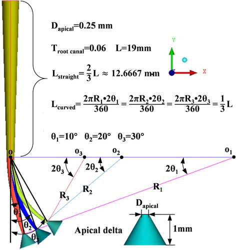
There are 3 types of angle (θ1, θ2, θ3) that can be called turning angle of the root canal, and the turning angle corresponding to the straight root canal is set to be zero. The apical delta of the root canal (or called apical anatomy) was modeled as an inverse cone pipe and its length is 1 mm. The irrigant, sodium hypochlorite (NaOCl) 3% aqueous solution was treated as an incompressible Newtonian fluid, the density (ρ) and dynamic viscosity (μ) of which are separately 1.074 g/cm3 and 1.037 × 10⁻³ Pa•s. Its attributes are different from nanofluid (Ahmadi et al., Citation2019; Ramezanizadeh et al., Citation2018), which is also treated as irrigation flow for a root canal in Ghalandari’s research (Ghalandari, Mirzadeh Koohshahi, et al., Citation2019). Gravity was considered during this numerical research and the direction of it is the negative Y-axis. By reference to the current popular commercial 30G needle, two basic needles which are respectively labeled by I and II in Figure have been created during the simulation. The flat exit of the first basic needle was at its end-tip (named open-ended flat needle) while the other one was side-vented called as the side-vented needle. Both the diameters (including the external, internal diameters) and length of these needles were standardized (that is Dext of 0.320 mm, Dint of 0.196 mm, Lneedle of 32 mm) in the first step of this research. In addition, all needles were centered within the root canal.
Figure 2. Sketch of the needle and the insertion depth.
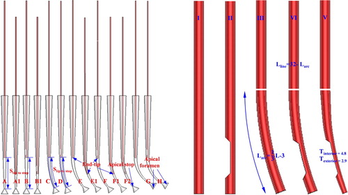
In other words, to explore the impact of the root-canal curvature and its variation on the irrigation efficiency, the turning angle of the root canal and the exit type of the needle were selected as variations in the first step. Thus, there are first 8 different schemes as shown in Table , in which the needle end-tip is fixed at the 1/3 point of the root canal centerline (that is Stip to stop = L/3). Subsequently, five additional schemes named A1, B1, E1, F1, and F2 have been added for comparison.
Table 1. Schemes studied in this research.
In these 5 added cases, except the value of Stip to stop has been changed to 3 mm, three new kinds of needles (separately labeled III, IV, and V) that developed from the two basic needles have been adopted. Among them, the needle III consists of a straight part and a curved part. The curved part has the same curvature to the root canal’s curved part and the same exit to needle I, as needle IV to needle II. Needle V has evolved from needle IV, and the only difference between them is that the curved part of needle IV has been changed to be a tapered pipe (Tinterior = 4.8, Texterior = 2.9).
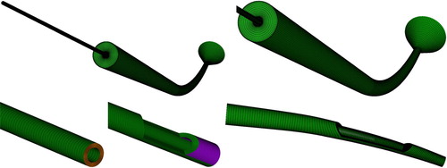
Mesh generation and numerical boundary conditions
The powerful mesh generator PointWise has been selected as the tool both for the 3d geometry construction and mesh creation. All meshes were of hexahedral structure, with a grid topology of O-type has been chosen to improve the quality of the mesh close to the inner wall of the root canal or the syringe needle, as shown in Figure . Considering complicated flow details in the microchannel (Ez Abadi et al., Citation2019; Ghahremannezhad & Vafai, Citation2018), meshes near the wall and the areas with strong velocity or turbulence gradients, were all locally refined. The same grid topology has been used for all schemes studied here to reduce the occurrence of the numerical discrepancy. The wall distance of the 1st layer grid in the whole calculation domain was set to 0.001 mm, with the y+ equaling 1.5. The grid resolution met the near-wall mesh guidelines, which were just corresponding to the turbulence model selected here. The grid independence was considered for determining the minimum amount of cells needed for numerical simulation. With the number of total grids changing from 0.5 million to 1.0 million through 0.75 million, the numerical accuracy was improved gradually. However, further refinement (1.25 million grids) led to insignificant changes. At last, considering the computation efficiency, the total quantity of mesh points of the whole model used for simulation was approximate one million. In this mesh-independency study, some key parameters have been selected as evaluation parameters, such as the apical pressure in the apical delta and the shear stress at the internal surface of the root canal.
Figure 3. The mesh used for simulation.
The internal surfaces not only of the root canal but also of the needle were set as rigid, smooth, no-slip impermeable boundaries. The whole calculation domain is filled with the irrigation solution which has been injected by the syringe needle. Finally, this solution flowed out of the root canal through its orifice, where a boundary condition of atmospheric pressure has been assumed. As to the inlet of the needle, it has been set as a velocity-inlet, the value of which is 8.6 m/s. This velocity just corresponding to the real volume flow rate (namely 0.26 mL/s) passing a commercial 30G needle in the clinic. The wall of the apical delta was simulated with the previous study (Boutsioukis, Gogos, et al., Citation2010b) as a reference, that is assuming it as a hard and impervious wall. No exception, the flutter(Ghalandari, Bornassi, et al., Citation2019; Ghalandari, Shamshirband, et al., Citation2019) of the needle is also ignored in this study like other similar investigations, though it inserts in the fast-moving fluid.
The tool used for numerical simulation is commercial CFD software FLUENT 14.0, which is widely used in these decades (Farzaneh-Gord et al., Citation2019). An implicit iterative solver has been used to solve the Navier-Stokes (N-S) equation set, which has been used to depict the unsteady, 3d, and density-invariant flow in the model investigated in this research. During the solving process of this equation set, the FVM (finite volume method) has been used. Besides, the flow has been assumed as an isothermal flow. At first, the steady solutions have been got, and then they have been taken as the initial conditions for unsteady simulations against transient effects. Considering both the physical model and the condition studied in this paper are similar to Gao’s research (Gao et al., Citation2009), some same settings about simulation have been adopted, such as the choice of SST k-ω turbulence model. The SST k-ω turbulence model has been concluded as the optimal one for simulation by comparing the simulational results and the corresponding experimental data (Gao et al., Citation2009) in detail. As discretizing the transport equations, at least second-order accurate has been ensured. Additionally, a time-step of 10−6 s has been set during the whole process of the calculation. The convergence criterion of 10−5 was set for the maximal scaled residuals. At the same time, some key parameters (such as pressure, velocity, and vorticity) have been monitored to guarantee adequate convergence. All computational work in this study has proceeded with a big computer cluster. The results of interest (velocity magnitude, wall shear stress distribution, flow pattern, and apical pressure) corresponding to all schemes were obtained and analyzed in detail.
Governing equations
The flow evolution was depicted with 3d unsteady and incompressible Navier-Stokes equations, namely,
(1)
(1)
(2)
(2) In the above formula,
is the Laplacian operator,
. As stated above, to solve the governing equations, a finite volume method with a fixed time step was used. The solver was set with second-order accuracy, and the SIMPLE algorithm was selected for pressure-velocity coupling.
Results
It is known that the irrigant replacement and the ability of the irrigation flow to remove the flotsam attaching on the internal wall of the root canal as well as the safety of irrigation operation from the clinical view, are three points of most concern during root canal irrigation. Therefore, the velocity of the irrigant fluid (including the size of the relative higher-velocity region), the shear stress on the internal wall of the root canal, and the apical pressure, which are three crucial evaluation parameters corresponding to above three points have been analyzed in detail in this study. Considering streamline can directly reflect flow patterns, the streamline of irrigant fluid has also been offered.
The velocity distribution on the symmetry planes (Z = 0) of different schemes has been offered in Figure . It is clear that the open-ended flat needle has more influence on the velocity distribution of the fluid that just downstream of the needle tip (Figure (a)). As for the side-vented syringe needle, it has more effect on the fluid around its sidewall, and the circumferential asymmetry is apparent (Figure (a)). The velocity distribution with local range legend was shown in Figure (b), from which the micro-velocity zone that just between the end of the syringe needle and the cross-section corresponding to the apical stop of the target root-canal may be easily found. The flow velocity of the fluid in this zone is close to zero, and this phenomenon has also been observed in Gao’s research (Gao et al., Citation2009). Following the growth of the insertion length of the syringe needle, such as changing the value of from L/3 to 3 mm, this micro-velocity zone decreases a lot. Besides, as the insertion depth keeps the same, the open-ended flat needle leads to less micro-velocity zone. However, compared to the change of the syringe needle type (that is replacing the side-vented one with the open-ended flat one), deepening the needle insertion has a more apparent effect in decreasing the micro-velocity zone.
Figure 4. The contours of velocity magnitude on the Z = 0 plane.
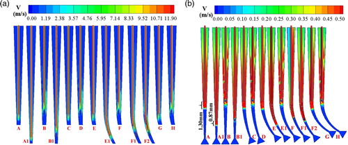
Vcenter is defined as the irrigant velocity component along the centerline direction of the root canal. Figure is the distribution of Vcenter on the Z = 0 plane and it provides an indicative view of irrigant replacement. The replacement of the irrigant extended about 1.3 mm apical to the end-tip of the open-ended flat syringe needle, but as to the side-vented one, it is limited within 1 mm. This result proves the information illustrated in Figure (b) again. The threshold value is 0.1 m/s, which has been thought of as the minimum velocity that can effectively remove the endodontic debris, the residuary pulps, and also the microbic biofilms in the target root canal in many previous studies. As an open-ended flat needle used for irrigation, the value of the Vcenter increases slowly with the increment of the turning angle of the root canal (Figure (b)). As for the side-vented syringe needle, the value of the Vcenter has changed little with the increase of the root canal turning angle (Figure (c)). Except for these, the existence of the micro-velocity zone has been verified by analyzing the irrigant velocity near the apical stop (Figure (b–e)).
Figure 5. The distribution of irrigant velocity component along the centerline on the Z = 0 plane with the coordinate Y.
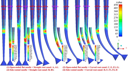
The shear stress distribution on the inner wall of the root canal differs among these various cases (Figure ). The enumeration of this difference has been put forward from 3 aspects: the circumferential uniformity, location of the maximum wall shear stress point, location of the larger high shear stress region. Firstly, the shear stress distribution around the irrigation needle end-tip is uniform in the circumferential direction as the open-ended flat needle is adopted in the straight root canal (scheme A and A1), whereas circumferential nonuniform distribution occurs as the side-vented needle is selected or the prepared root canal for irrigation is a curved one. When using the open-ended flat needle for irrigation, the curvature part of the curved root canal leads to the maximum wall shear stress point appears on the inside wall (as labeled in Figure (a)) of the root canal curved part no matter the needle itself is curved or not. In other words, it has little relationship with the insertion depth of the open-ended flat needle, as schemes C, E, E1, and G shown. As for the side-vented needle, the inserted depth of the needle becomes an important influential factor. Through the comparison of the shear stress patterns of scheme B, D, F, and H, we can find that the maximum shear stress point with the same value (430 Pa) appears on the wall that is just facing the needle exit, as the needle end-tip is fixed at the 1/3 point of the root canal and needles selected are straight side-vented needles, no matter the root canal is curved or not. But as the value of Stip to stop has been decreased to 3 mm, namely scheme B1, F1, and F2, the shear stress distribution that just around the needle exit becomes more complicated. Similar to schemes C, E, E1, and G, the maximum shear stress point occurs opposite to the internal surface facing the syringe needle exit (namely, the inside wall of the root canal curved portion) in scheme B1 and F2. However, a different distribution emerges in scheme F1: the maximum shear stress point occurs on the inner wall facing the syringe needle exit. What should be noticed is that, irrespective of the needle type, deeper needle insertion not only brings a larger value of the maximum wall shear stress but also a larger high wall shear stress region. Furthermore, the larger one of the two sides of this asymmetrical high shear stress region always appears at the wall opposite to the internal surface facing the side-vented exit, or the inside wall of the arc portion as the open-ended flat needle has been selected.
Figure 6. The contours of the root canals’ wall shear stress.
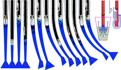
Both streamlines and low-velocity contours on the Z = 0 plane have been given in Figure . The streamlines not only show the whole route of fluid since it emptied into the calculation domain from the syringe needle inlet in three dimensions but also verifies the circumferential flow pattern from a more essential perspective. After all, the flow pattern produces the wall shear stress distribution and not the other way around. In the picture, the blue region represents the low-velocity region where the fluid velocity is less than 0.1 m/s. Clearly, the open-ended flat and side-vented needles produce completely different streamline distributions in the same root canal. The structural asymmetric exit of the side-vented needle results in apparent nonuniform streamline distribution in the circumferential direction. Although the curvature of the root canal also leads to nonuniformity, its effect differs with the variation of the needle type. When the open-ended flat needle has been used for irrigation (scheme A, A1, C, E, E1, G), curvature variation of the curved root canal has a stronger effect on the streamline pattern in the region around the needle exit, especially as the turning angle of the root canal changes from zero to the non-zero condition. Nevertheless, with the increase of the non-zero turning angle of the curved root canal, the internal streamline distribution only changes a little as schemes C, E, and G shown in Figure . As to the side-vented needle, no matter for the group of schemes with shallower insertion (B, D, F, H) or the group of schemes with deeper insertion (B1, F1, F2), the effect of the root canal curvature variation on the streamline distribution is much lower.
Figure 7. The streamlines and low-velocity contours on the Z = 0 plane in different schemes.
Considering higher apical-foramen pressure means a relatively high risk that the irrigant has been extruded into the periapical tissue, average total pressures at the apical stop and foramen have been given in Table . Apparently, needle type and insertion depth are two major factors. The variation in either of them can affect the average total pressure at the cross-section corresponding to the apical stop or the apical foramen significantly. The side-vented type brings relative lower-level pressure at the apical stop and foramen but lower efficiency of irrigant replacement as depicted in Figures and . The open-ended flat needle is exactly the opposite.
Table 2. Averaged total pressure at the apical stop and apical foramen.
With the increment of the insertion depth of the needle for irrigation, the area-average total pressure increases a lot. Relative to the open-ended flat needle, the side-vented one is more easily to result in lower pressure, and this tendency becomes more apparent with the needle insertion deepened (the group of scheme A, B versus the group of scheme A1, B1; the group of scheme E, F versus the group of scheme E1, F1). Besides, there is nearly no deviation between the mean total pressure at the location of the apical stop and that at the location of the apical foramen in all schemes listed here.
As to the effect of the curved structure of the root canal on the apical pressure, there is a noticeable phenomenon. In the case of the needle whole staying in the upstream straight part of the root canal, average apical total pressure varies little as the turning angle of the root canal increases from 0° to 30°, no matter for the group consisting of scheme A, C, E, and G with an open-ended flat needle or another group including scheme B, D, F and H with a side-vented needle. Nonetheless, a bigger difference occurs once the needle inserts into the root canal curved part, particularly as the open-ended flat needle has been selected for irrigation, such as scheme A1 and E1 shown in the table. Comparing scheme B1 and F1, it can be found that the average total pressure of them shows little difference. What’s more, the difference raised a lot when the clearance between the outside surface of the end-tip of the syringe needle and internal surface of the target root canal changed, such as scheme F1 and F2.
Discussion
Despite the large usage of the curved root canal as a geometric model, few investigations have concerned the effect of root canal curvature on needle irrigation efficiency. So, in this study, numerical simulation of flow in 3d prepared curved root canal with CFD method has been conducted, which aims at finding flow field details in this type of root canal and also the corresponding irrigation strategy. With the detailed analysis of Figures and , the results about circumferential nonuniform wall shear stress (from three respects) and streamline distribution have been summarized. In fact, the phenomena shown in these pictures were mainly caused by the characteristic effect of the root canal curved structure and the side-vented exit orientation.
For the curved root canal, the inside wall of its arc part is not parallel to the outside wall. Consequently, the outside wall has a completely different reaction against the coming flow as the needle exit just positing at the center. As the open-ended flat needle has been selected for irrigation, both the maximum wall shear stress point and the larger one of the two sides of the asymmetrical high shear stress region always occurs at the inside wall of the curved needle, and the result of scheme C, E, E1, G given in Figure is a good proof. Additionally, the curvature variation significantly influences the flow details around the end-tip of the irrigation needle only when the open-ended flat needle has been selected for irrigation (scheme A, C, E, G with shallower insertion, or scheme A1, E1 with deeper insertion) or the side-vented needle has been inserted into the curved part of the root canal (scheme B1, F1, F2). As the needle of a side-vented port has been selected for irrigation and its end tip locates at the L/3 point (that is Stip to stop = L/3), the distributions of these parameters change a little with the increment of the root canal turning angle (scheme B, D, F, H). These mentioned phenomenons which are about the open-ended flat syringe needle mainly due to more fluid turns back and flows toward the orifice of the root canal through the gap between the outer surface of the syringe needle and the inside wall of the root canal. The underlying mechanism is the continuity equation and the incompressibility of the irrigant flow. As to the phenomenons corresponding to the side-vented needle, it has a great relationship with the specific flow characteristic of the side-vented exit as interpreted below.
As to the side-vented exit, the direction of the main flow out of it has changed. Then, due to the sudden expansion of the flow passage (Boutsioukis, Verhaagen, Versluis, Kastrinakis, & van der Sluis, Citation2010), the irrigant flow turned into a side-impinging jet near the exit of the syringe needle. As a result, the main flow itself becomes no longer circumferential uniform since out from the side-vented port. Besides, the location of the exit of the syringe side-vented needle is relatively upper except that the flow area of it is bigger than the exit of the open-ended flat needle. Thus, the high-velocity zone, which is just downstream of the open-ended flat needle end-tip is larger than that down the side-vented one with the same needle insertion, as shown in Figure . Moreover, the nonuniformity caused by the orientation change of the main flow (such as from scheme A to scheme B, or from scheme C to scheme D) brings a larger impact on the formation of the circumferential nonuniform wall shear stress (Figure ) or asymmetric streamline distribution (Figure ) than the effect of the single root canal curvature variation (such as from scheme A to scheme C or E or G, or scheme C to scheme E or G). This is owing to the single root canal curvature variation leads to no topological structure change while the needle side-vented exit results in.
There can be no doubt that the circumferential non-uniformity flow pattern mentioned above is indeed not good for the improvement of irrigation efficiency. In the face of this non-uniformity, some corresponding responses can be put forward. For example, changing the open notch orientation of the selected side-vented needle (such as facing the inside wall of the curved part) or putting the needle closer or further to the outside wall of the arc tube instead of locating in the center of the root canal. However, according to previous researches about the effects of the needle position (Boutsioukis, Verhaagen, Versluis, Kastrinakis, et al., Citation2010; Wang et al., Citation2015) or tilting angle (Adiguzel et al., Citation2016) variations on the irrigant flow, it can be concluded that these methods are just a little effective for the improvement of the circumferential non-uniformity. Fortunately, during the root canal irrigation, the circumferential uniformity of the shear stress or streamline distribution is not worthy of attention as the micro-velocity zone and the apical pressure.
Needle insertion depth variation has a significant effect on the efficiency of irrigant replacement via directly affecting the size of the micro-velocity zone. Because deeper needle insertion leads to the more relative higher-velocity fluid to the apical stop (AS), the micro-velocity zone decreases as the insertion depth of the syringe needle increases. Obviously, the insertion depth of 2 L/3 studied here (that is Stip to stop = L/3) is not enough for there was a large micro-velocity zone, especially as the side-vented needle used for irrigation. Although the penetration of the curved needle into the root canal with the same curvature may be difficult to realize in the clinical root canal irrigation process at present, doing corresponding research is still necessary for several reasons. First of all, the curved root canal is common in the clinic. Secondly, the size of the micro-velocity zone can be decreased a lot with the increment of the insertion depth of the curved needle, which is verified by the results of scheme A1, E1, F1, and F2 studied in this article. Last but not least, with current manufacturing technology, the curved needle with a relatively deformable curved part made of plastic or other material is possible. The average total pressure at the cross-section of the apical stop is almost equal to that at the cross-section of the apical foramen, mainly because both the apical stop and the apical foramen are contained in the micro-velocity zone, which means no active fluid flow into the apical delta zone through the apical stop section. A similar conclusion about needle insertion has also been revealed respectively by Boutsioukis (Boutsioukis, Lambrianidis, et al., Citation2010) and Psimma (Psimma et al., Citation2013). However, there is no detailed analysis of the internal flow pattern in the latter one (Psimma et al., Citation2013).
As for the constant presence of the micro-velocity zone in this research, it may be attributed to the shallower needle insertion or the velocity setting at the inlet of the needle is not high enough. In theory, the micro-velocity zone will reduce significantly if the velocity is high enough. Paradoxically, the apical foramen pressure will be too high to endure if the fluid velocity at the syringe needle inlet increases a lot or the needle end-tip is too close to the apical stop. This is can be verified by the data corresponding to scheme A1, B1, E1, F1, and F2 given in Table . On the base of fluid dynamic theory and the results of a large number of numerical simulation or clinical experimental researches, we know high pressure can cause extrusion of the irrigant into the periapical tissue (Hülsmann et al., Citation2009; Verhaagen et al., Citation2012). Clearly, the side-vented syringe needle is better for keeping low apical pressure than the open-ended flat needle. Taken together, the curved side-vented needle with deeper insertion seems more suitable for the no-dead space irrigant extrusion in the curved root canal and ensuring the low apical pressure requirement at the same time. Moreover, by comparing the data that respectively corresponding to scheme F1 and F2 (shown in Table ), it is certain that the deeper needle insertion with a smaller clearance between the outer surface of the syringe needle end-tip and the internal surface of the target root canal is much better.
For seeking the intrinsic mechanism of the complex flow characteristic in the root canal during 13 schemes researched here, the blue micro-velocity zones in Figure has been linked with the data listed in Table for deep analysis. It is not difficult to find that a longer blue micro-velocity zone means lower apical pressure. Due to the flow direction alteration of the fluid coming out of the side-vented needle exit, the component of its momentum in the minus z-direction decreases a lot. Whereas, as shown in the right up corner of Figure , nearly all the momentum of the jet flow out of the open-ended flat needle exit is in the minus z-direction. According to the momentum equation, one factor has a very important impact. It is where and how much amount of high-speed fluid out of the needle exit directly change their original direction to flow back to the root canal orifice, without arriving at the apical stop through the clearance between the outer surface of the syringe needle for irrigation and the internal surface of the target root canal. When the model of the root canal and the velocity at the inlet of the syringe needle keep constant, more amount fluid flowing back at a further upstream location means lower total pressure at the cross-section corresponding to the root-canal apical stop or foramen. Therefore, the side-vented syringe needle with shallower insertion and smaller gap size between its end tip and the internal surface of the target root canal leads to lower apical pressure.
Conclusions and expectation
In summary, the present study has conducted 3d CFD numerical simulations to investigate the flow pattern of irrigation in a series of curved root canals. It is can be found that the optimal method for irrigation in this kind of curved root canal is the curved side-vented needle with deeper insertion, and also with reasonable needle end-tip size, which can guarantee a little gap between the outer surface of the syringe needle end tip and the internal surface of the target root canal. The expectation of this investigation is the systematic experiments in the clinic in the following study.
Acknowledgments
The author(s) disclosed receipt of the following financial support for the research, authorship, and/or publication of this article: The Open Project of State Key Laboratory of Clean Energy Utilization, Zhejiang University (grant numberZJUCEU2011002), The Foundation of Key Research and Development Plan in Zhejiang Province in China (grant number 2018C04002), and China Postdoctoral Science Foundation (grant number 2020M671717).
Disclosure statement
No potential conflict of interest was reported by the author(s).
Additional information
Funding
References
- Abou-Rass, M., & Piccinino, M. V. (1982). The effectiveness of four clinical irrigation methods on the removal of root canal debris. Oral Surgery, Oral Medicine, Oral Pathology, 54(3), 323–328. https://doi.org/10.1016/0030-4220(82)90103-7
- Adiguzel, O., Gokcen, M. G., & Olcay, A. B. (2016). Evaluation of the effect of needle tilting angle on irrigant flow in the root canal using side-vented needle by an unsteady computational fluid dynamics model. International Dental Research, 6(1), 1–8. https://doi.org/10.5577/intdentres.2016.vol6.no1.1
- Ahmadi, M. H., Ghahremannezhad, A., Chau, K.-W., Seifaddini, P., Ramezannezhad, M., & Ghasempour, R. (2019). Development of simple-to-use predictive models to determine thermal properties of Fe2O3/water-ethylene glycol nanofluid. Computation, 7(1), 18. https://doi.org/10.3390/computation7010018
- Arvand, A., Hormes, M., & Reul, H. (2005). A validated computational fluid dynamics model to estimate hemolysis in a rotary blood pump. Artificial Organs, 29(7), 531–540. https://doi.org/10.1111/j.1525-1594.2005.29089.x
- Boutsioukis, C., Gogos, C., Verhaagen, B., Versluis, M., Kastrinakis, E., & Van der Sluis, L. W. (2010a). The effect of apical preparation size on irrigant flow in root canals evaluated using an unsteady computational fluid dynamics model. International Endodontic Journal, 43(10), 874–881. https://doi.org/10.1111/j.1365-2591.2010.01761.x https://www.ncbi.nlm.nih.gov/pubmed/20618879
- Boutsioukis, C., Gogos, C., Verhaagen, B., Versluis, M., Kastrinakis, E., & Van der Sluis, L. W. (2010b). The effect of root canal taper on the irrigant flow: Evaluation using an unsteady computational fluid dynamics model. International Endodontic Journal, 43(10), 909–916. https://doi.org/10.1111/j.1365-2591.2010.01767.x https://www.ncbi.nlm.nih.gov/pubmed/20618877
- Boutsioukis, C., Lambrianidis, T., & Kastrinakis, E. (2009). Irrigant flow within a prepared root canal using various flow rates: A computational fluid dynamics study. International Endodontic Journal, 42(2), 144–155. https://doi.org/10.1111/j.1365-2591.2008.01503.x https://www.ncbi.nlm.nih.gov/pubmed/19134043
- Boutsioukis, C., Lambrianidis, T., Verhaagen, B., Versluis, M., Kastrinakis, E., Wesselink, P. R., & van der Sluis, L. W. (2010). The effect of needle-insertion depth on the irrigant flow in the root canal: Evaluation using an unsteady computational fluid dynamics model. Journal of Endodontics, 36(10), 1664–1668. https://doi.org/10.1016/j.joen.2010.06.023 https://www.ncbi.nlm.nih.gov/pubmed/20850673
- Boutsioukis, C., Verhaagen, B., Versluis, M., Kastrinakis, E., & van der Sluis, L. W. (2010). Irrigant flow in the root canal: Experimental validation of an unsteady computational fluid dynamics model using high-speed imaging. International Endodontic Journal, 43(5), 393–403. https://doi.org/10.1111/j.1365-2591.2010.01692.x https://www.ncbi.nlm.nih.gov/pubmed/20518932
- Boutsioukis, C., Verhaagen, B., Versluis, M., Kastrinakis, E., Wesselink, P. R., & van der Sluis, L. W. (2010). Evaluation of irrigant flow in the root canal using different needle types by an unsteady computational fluid dynamics model. Journal of Endodontics, 36(5), 875–879. https://doi.org/10.1016/j.joen.2009.12.026 https://www.ncbi.nlm.nih.gov/pubmed/20416437
- Chen, J. E., Nurbakhsh, B., Layton, G., Bussmann, M., & Kishen, A. (2014). Irrigation dynamics associated with positive pressure, apical negative pressure and passive ultrasonic irrigations: A computational fluid dynamics analysis. Australian Endodontic Journal, 40(2), 54–60. https://doi.org/10.1111/aej.12027 https://www.ncbi.nlm.nih.gov/pubmed/25244218
- Devi, A. A., & Abbott, P. V. (2012). Comparison of the flow characteristics of irrigants with standard and max-i-probe needles. Australian Endodontic Journal, 38(2), 50–54. https://doi.org/10.1111/j.1747-4477.2012.00354.x https://www.ncbi.nlm.nih.gov/pubmed/22827815
- Dioguardi, M., Gioia, G. D., Illuzzi, G., Laneve, E., Cocco, A., & Troiano, G. (2018). Endodontic irrigants: Different methods to improve efficacy and related problems. European Journal of Dentistry, 12(3), 459–466. https://doi.org/10.4103/ejd.ejd_56_18 https://www.ncbi.nlm.nih.gov/pubmed/30147418
- Ez Abadi, A. M., Sadi, M., Farzaneh-Gord, M., Ahmadi, M. H., Kumar, R., & Chau, K.-w. (2019). A numerical and experimental study on the energy efficiency of a regenerative Heat and Mass Exchanger utilizing the counter-flow Maisotsenko cycle. Engineering Applications of Computational Fluid Mechanics, 14(1), 1–12. https://doi.org/10.1080/19942060.2019.1617193
- Farzaneh-Gord, M., Faramarzi, M., Ahmadi, M. H., Sadi, M., Shamshirband, S., Mosavi, A., & Chau, K.-w. (2019). Numerical simulation of pressure pulsation effects of a snubber in a CNG station for increasing measurement accuracy. Engineering Applications of Computational Fluid Mechanics, 13(1), 642–663. https://doi.org/10.1080/19942060.2019.1624197
- Gao, Y., Haapasalo, M., Shen, Y., Wu, H., Li, B., Ruse, N. D., & Zhou, X. (2009). Development and validation of a three-dimensional computational fluid dynamics model of root canal irrigation. Journal of Endodontics, 35(9), 1282–1287. https://doi.org/10.1016/j.joen.2009.06.018 https://www.ncbi.nlm.nih.gov/pubmed/19720232
- Ghahremannezhad, A., & Vafai, K. (2018). Thermal and hydraulic performance enhancement of microchannel heat sinks utilizing porous substrates. International Journal of Heat and Mass Transfer, 122, 1313–1326. https://doi.org/10.1016/j.ijheatmasstransfer.2018.02.024
- Ghalandari, M., Bornassi, S., Shamshirband, S., Mosavi, A., & Chau, K. W. (2019). Investigation of submerged structures’ flexibility on sloshing frequency using a boundary element method and finite element analysis. Engineering Applications of Computational Fluid Mechanics, 13(1), 519–528. https://doi.org/10.1080/19942060.2019.1619197
- Ghalandari, M., Mirzadeh Koohshahi, E., Mohamadian, F., Shamshirband, S., & Chau, K. W. (2019). Numerical simulation of nanofluid flow inside a root canal. Engineering Applications of Computational Fluid Mechanics, 13(1), 254–264. https://doi.org/10.1080/19942060.2019.1578696
- Ghalandari, M., Shamshirband, S., Mosavi, A., & Chau, K.-w. (2019). Flutter speed estimation using presented differential quadrature method formulation. Engineering Applications of Computational Fluid Mechanics, 13(1), 804–810. https://doi.org/10.1080/19942060.2019.1627676
- Haapasalo, M., Shen, Y., Wang, Z., & Gao, Y. (2014). Irrigation in endodontics. British Dental Journal, 216(6), 299–303. https://doi.org/10.1038/sj.bdj.2014.204 https://www.ncbi.nlm.nih.gov/pubmed/24651335
- Hülsmann, M., Rödig, T., & Nordmeyer, S. (2009). Complications during root canal irrigation. Endodontic Topics, 16(1), 27–63. https://doi.org/10.1111/j.1601-1546.2009.00237.x
- Koch, J. D., Smith, N. A., Garces, D., Gao, L., & Olsen, F. K. (2014). In vitro particle image velocity measurements in a model root canal: Flow around a polymer rotary finishing file. Journal of Endodontics, 40(3), 412–416. https://doi.org/10.1016/j.joen.2013.10.038 https://www.ncbi.nlm.nih.gov/pubmed/24565662
- Ma, Y., Han, J., Yu, H., & X., W. (2015). Computational fluid dynamics analysis of the flow of four irrigations in root canal. Zhonghua Kou Qiang Yi Xue Za Zhi, 50(6), 352–357. https://doi.org/10.3760/cma.j.issn.1002⁃0098.2015.06.007
- Malki, M., Verhaagen, B., Jiang, L. M., Nehme, W., Naaman, A., Versluis, M., Wesselink, P., & van der Sluis, L. (2012). Irrigant flow beyond the insertion depth of an ultrasonically oscillating file in straight and curved root canals: Visualization and cleaning efficacy. Journal of Endodontics, 38(5), 657–661. https://doi.org/10.1016/j.joen.2012.02.001 https://www.ncbi.nlm.nih.gov/pubmed/22515896
- Pekkan, K., de Zelicourt, D., Ge, L., Sotiropoulos, F., Frakes, D., Fogel, M. A., & Yoganathan, A. P. (2005). Physics-driven CFD modeling of complex anatomical cardiovascular flows-a TCPC case study. Annals of Biomedical Engineering, 33(3), 284–300. https://doi.org/10.1007/s10439-005-1731-0 https://www.ncbi.nlm.nih.gov/pubmed/15868719
- Pereira, M. R., Morouço, P., Vasconcelos, I., Franco, M., Alves, N., & Ginjeira, A. (2018). Computer fluid dynamics as a tool for analysis of endodontic irrigation.
- Psimma, Z., Boutsioukis, C., Kastrinakis, E., & Vasiliadis, L. (2013). Effect of needle insertion depth and root canal curvature on irrigant extrusion ex vivo. Journal of Endodontics, 39(4), 521–524. https://doi.org/10.1016/j.joen.2012.12.018 https://www.ncbi.nlm.nih.gov/pubmed/23522549
- Ramezanizadeh, M., Alhuyi Nazari, M., Ahmadi, M. H., & Chau, K.-w. (2018). Experimental and numerical analysis of a nanofluidic thermosyphon heat exchanger. Engineering Applications of Computational Fluid Mechanics, 13(1), 40–47. https://doi.org/10.1080/19942060.2018.1518272
- Rodriguez-Figueroa, C., McClanahan, S. B., & Bowles, W. R. (2014). Spectrophotometric determination of irrigant extrusion using passive ultrasonic irrigation, EndoActivator, or syringe irrigation. Journal of Endodontics, 40(10), 1622–1626. https://doi.org/10.1016/j.joen.2014.03.017 https://www.ncbi.nlm.nih.gov/pubmed/25260734
- Shen, Y., Gao, Y., Qian, W., Ruse, N. D., Zhou, X., Wu, H., & Haapasalo, M. (2010). Three-dimensional numeric simulation of root canal irrigant flow with different irrigation needles. Journal of Endodontics, 36(5), 884–889. https://doi.org/10.1016/j.joen.2009.12.010 https://www.ncbi.nlm.nih.gov/pubmed/20416439
- Shirazi, M. M., Abouali, O., Emdad, H., Nabavizadeh, M., Mirhadi, H., & Ahmadi, G. (2017). Numerical and analytical investigation of irrigant penetration into dentinal microtubules. Computers in Biology and Medicine, 89, 1–17. https://doi.org/10.1016/j.compbiomed.2017.07.013 https://www.ncbi.nlm.nih.gov/pubmed/28772174
- Verhaagen, B., Boutsioukis, C., Heijnen, G. L., van der Sluis, L. W. M., & Versluis, M. (2012). Role of the confinement of a root canal on jet impingement during endodontic irrigation. Experiments in Fluids, 53(6), 1841–1853. https://doi.org/10.1007/s00348-012-1395-0
- Wang, R., Shen, Y., Ma, J., Huang, D., Zhou, X., Gao, Y., & Haapasalo, M. (2015). Evaluation of the effect of needle position on irrigant flow in the C-shaped root canal using a computational fluid dynamics model. Journal of Endodontics, 41(6), 931–936. https://doi.org/10.1016/j.joen.2015.02.002 https://www.ncbi.nlm.nih.gov/pubmed/25791077
- Xu, C., Sin, S., McDonough, J. M., Udupa, J. K., Guez, A., Arens, R., & Wootton, D. M. (2006). Computational fluid dynamics modeling of the upper airway of children with obstructive sleep apnea syndrome in steady flow. Journal of Biomechanics, 39(11), 2043–2054. https://doi.org/10.1016/j.jbiomech.2005.06.021 https://www.ncbi.nlm.nih.gov/pubmed/16098533
- Yang, X. L., Liu, Y., & Luo, H. Y. (2006). Respiratory flow in obstructed airways. Journal of Biomechanics, 39(15), 2743–2751. doi:10.1016/j.jbiomech.2005.10.009 Retrieved from https://www.ncbi.nlm.nih.gov/pubmed/16300771