
 ?Mathematical formulae have been encoded as MathML and are displayed in this HTML version using MathJax in order to improve their display. Uncheck the box to turn MathJax off. This feature requires Javascript. Click on a formula to zoom.
Abstract
Significant nonlinearity of electronic hydraulic brake (EHB) systems often leads to complex hydraulic force control responses. This paper designs a motor-driven EHB system and analyzes nonlinear friction induced by the deceleration mechanism. To compensate this friction, a flutter signal is added to the controller input. In addition, this paper designs a fuzzy-PI (Proportional and Integral) controller for the cylinder hydraulic pressure of the EHB system based on the opening and closing characteristics of a solenoid valve. Response curves of cylinder hydraulic pressure are obtained under three different input signals: step, triangular, and sinusoidal. The co-simulation model is established by AMEsim™ and Simulink® ansofts. The study results indicate that the proposed hydraulic-force-following control method of the EHB system can follow different input signals well. A step response test and a sine-wave-following test are carried out, which correspond to the EHB response in the case of driver’s emergency braking and frequent braking, respectively. Stable and rapid pressure build-up is obtained under different step target hydraulic pressures. Therefore, the hydraulic-force-following control method of the EHB system based on a fuzzy-PI controller can satisfy the EHB system accuracy requirements for an electric vehicle, which is a certain valuable for the automobile industry.
1. Introduction
1.1. Research background
Electrification, intelligence and networking are hot topics in the field of automotive engineering (Si et al., Citation2014). The realization of intelligent driving depends on chassis drive-by-wire technology. The hydraulic brake system (EHB) belongs to the technology branch of braking by wire in chassis drive by wire, which has also promoted the development of braking from traditional braking to brake-by-wire systems (Chen et al., Citation2020). The EHB system used in new energy vehicles has the advantages of safety, comfort, fast response, easy realization of regenerative braking, and accurate control of braking force (Yu et al., Citation2017).
1.2. Literature review
The EHB system is a complex nonlinear system involving signal processing and parameter estimation (Castillo et al., Citation2016). Controlling its hydraulic pressure accurately is difficult. Therefore, it is necessary to propose a practical, accurate and reliable EHB hydraulic-pressure-following control method.
So far, significant studies have contributed to improving the performance of EHB systems. For example, Liu et al. (Citation2017) proposed an integrated electronic hydraulic braking system. Based on this system, a safety priority control strategy and a main cylinder constant frequency and voltage regulation control strategy were designed to study Anti-lock Braking Systems
(ABSs) that could demonstrably improve braking efficiency and work in combination with an Electronic Stability Program (ESP) system. Yang and Wu (Citation2017) proposed a driver braking intention recognition method based on fuzzy logic, and carried out hardware-in-the-loop experiments on this method under typical working conditions, which were able to identify the driver’s braking intention effectively, but they did not consider braking cylinder pressure control. After Kalman-filter and sliding-mode control, Yong et al. (Citation2017) proposed a hydraulic force control method that was used in the EHB system with a motor drive and deceleration mechanism. Hardware-in-the-loop simulation experiments were carried out. The system response time was short and the brake pedal felt good. Li et al. (Citation2015) proposed an electro-mechanical line-controlled braking system. Simulink® and Stateflow® software were used for hydraulic-force-following control, which could control the braking hydraulic pressure of each cylinder independently, but did not involve vehicle stability further. Wei et al. (Citation2017) integrated yaw stability control into the EHB system to increase braking force and improve the yaw angular speed tracking capability. Oshima et al. (Citation2011) took the hydraulic pressure of the main cylinder directly as the control variable, being easy to observe and realize, but did not achieve accurate control in the low pressure range. Salih et al. (Citation2019) proposed a new method, called a “coperative active neuro-fuzzy inference system” for modeling evaporation using meteorological variables, which could only simulate evaporation from average temperature and relative humidity; but the efficiency of the Nash–Sutcliffe model reaches 0.93, which is much superior. Baghban et al. (Citation2019) gathered 1277 experimental data points of different nanofluid relative viscosities based on a review of the literature, and also established a fuzzy inference system based on an accommodative network to construct a common model.
1.3. Scientific and engineering contributions
The main innovation of this paper is that, facing the problems of low control accuracy and long response time in EHB hydraulic pressure control, this paper analyzes the nonlinear friction of the transmission mechanism in the EHB configuration, establishes a corresponding simplified model, adds chatter signal as friction compensation, and proposes a fuzzy-PI control method to follow different target hydraulic pressures. The proposed fuzzy-PI control method has higher precision (±1 bar), better stability, and a shorter response time (within 250 ms).
In a word, the hydraulic-force-following control method of the EHB system based on fuzzy proportional and integral control can meet the control accuracy requirements of the EHB system for an electric vehicle, which is invaluable for certain scientific and engineering applications in the automobile industry
1.4. Research work
To improve the accuracy and response time in the current EHB system, this paper designs a new EHB system whose hydraulic force control is based on the fuzzy-PI control method. For the main cylinder, a reliable friction compensation method is selected to describe the large nonlinearity of the deceleration mechanism of the motor-driven EHB system. For the braking wheel cylinder, a fuzzy proportional and integral control method can be used to analyze the switching characteristics of solenoid valves. A co-simulation model is built to follow the hydraulic pressure of the EHB system accurately. Finally, a vehicle test is carried out to verify the model. In the vehicle test, a step response test and a sine-wave- following test are carried out, respectively, and a better hydraulic pressure response is obtained.
2. EHB system scheme
The designed motor-driven EHB system structure scheme is illustrated in Figure .
Figure 1. EHB system configuration. 1-ECU; 2-battery; 3-motor; 4-bevel gear drive unit; 5-gear; 6-rack; 7-push rod; 8-first piston of brake master cylinder; 9-first working chamber of brake master cylinder; 10-liquid storage tank; 11-secondary piston of brake master cylinder; 12-second working chamber of brake master cylinder; 13-brake master cylinder; 14-ABS/ESP; 15-switch valve; 16-pedal simulator; 17-control valve; 18-first hydraulic pressure sensor; 19-second hydraulic pressure sensor; 20-mode switching valve; 21-Secondary master cylinder; 22-pedal push rod; 23-pedal displacement sensor; 24-pedal.
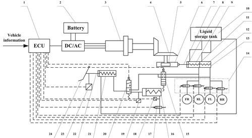
The EHB system comprises the pedal unit, the pressure building unit, the brake execution unit and the control unit. The EHB system working process is described as follows (Yang & Han, Citation2017). The pedal unit connected with the brake pedal provides the input signal of brake pedal displacement to the control unit. Figure indicates that the pressure building unit is a secondary mechanical transmission mechanism driven by a motor. The brake execution unit contains the brake master cylinder, the brake pipeline and the brake wheel cylinder.
The working procedures of the EHB system are analyzed. When the vehicle driver depresses the brake pedal, the sensors send some signals to the motor. Based on these signals, Figure indicates that the ECU can calculate the hydraulic braking force and transmit a torque signal to the motor, then drive the second-order deceleration mechanism and build pressure. At the same time, the solenoid valves of the four cylinders open and hydraulic oil flows into the brake cylinder to initiate the braking process.
3. Analysis of the deceleration mechanism of the EHB system
The dynamic model of the motor input force and the hydraulic pressure of the main brake cylinder is established, as shown in formula (1). The drive mechanism of the motor connection is a worm gear, worm, and gear rack.
(1)
(1) where
is the moment of inertia of motors and worm,
is the motor shaft damping coefficient,
is the motor torque,
is the worm end torque,
is the angle at which the motor shaft rotates,
is the moment inertia of the worm wheel,
is the rotational damping coefficient of the worm gear,
is the angle at which the gear rotates,
is the deceleration ratio of the worm and worm gear deceleration mechanism,
is the torque at the gear end,
is the rack and piston mass of the main cylinder,
is the rack displacement,
is the rack damper,
is the dimension of the force converted from the gear-rack mechanism moment,
is the first working chamber pressure of the main brake cylinder, and
is the inner diameter area of the main brake cylinder.
On the one hand, the worm gear combination has high structural strength, safety and reliability, and long service life. On the other hand, it has been used in EPS system for many years. The established friction model is shown in formula (2). The friction characteristics of worm gear and rack gear reduction mechanism are analyzed by using the friction model of Yuan et al. (Citation2016).
(2)
(2) Here,
is the friction,
is the static friction,
is the dynamic friction, and
is the speed of movement.
3.1. Mathematical modeling
In order to highlight the nonlinear characteristics of the deceleration mechanism, the motor, the deceleration mechanism, and the brake hydraulic system are simplified to a single mass vibration model with friction, as shown in Figure (Yuan et al., Citation2018). Figure shows that F is the thrust on the push rod of the brake cylinder, f is the friction force, and P is the hydraulic resistance.
Figure 2. Simplified model of system friction.
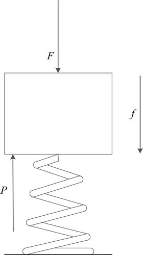
According to a simplified model of system friction, a mathematical model of the EHB system deceleration mechanism is established, as shown in formula (3):
(3)
(3) where
is the system equivalent mass,
is the damping factor,
is the system equivalent elastic factor, and
is the main cylinder push-rod displacement.
Formula (2) shows that the friction force of the system is nonlinear, and the hydraulic pressure can be compensated effectively by adding a flutter signal (Kong et al., Citation2010). A mathematical model of the EHB system with flutter signal is established as shown in formula (4):
(4)
(4) where
is the flutter signal,
is the vibration frequency, and
is the amplitude.
3.2. Friction compensation control
Based on the mathematical model of the EHB system with flutter signal, a simulation model of the EHB system is established and tested by an hydraulic step response simulation experiment. A 6 MPa step target pressure is input to the EHB simulation system controlled by PI and the EHB system with flutter signal, respectively. The simulation results are shown in Figure .
Figure 3. Setp signal tracking.
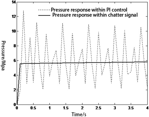
Figure shows that, when only the PI controller is used to track the target signal, the actual hydraulic pressure of the system oscillates sharply up and down at 6 MPa, and the root-mean-square error is 3.3566 MPa, resulting in system instability caused by the combined action of the proportional term and the friction force. After adding a flutter signal with 0.1 amplitude and 30 Hz frequency to compensate the friction force, the actual hydraulic pressure of the system can reach 5.55 MPa after 0.1 s, which can better follow the target hydraulic pressure.
4. Cylinder hydraulic force control
4.1. Characteristic analysis of solenoid valve
When the solenoid valve works, the spool moves under the combined action of the electromagnetic force, the liquid pressure, the spring force, the friction force, and the damping force. Zhao et al. (Citation2016) proposed a general method for neglecting the friction and damping forces, which is used in this paper.
The solenoid valve core has a certain quality: in the process of opening and closing the solenoid valve there is a certain delay between the control signal and the response of the motion of the solenoid valve core. The response curve of the normally open solenoid valve is expressed in Figure .
Figure 4. Response curve of normally open solenoid valve.
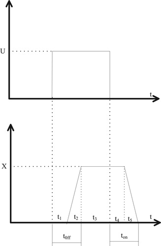
Figure indicates that U is the solenoid coil control voltage and X is the solenoid core displacement. There are five stages based on the X−t response curves of the solenoid valve as shown in Figure , in which the closing lag time is , the closing motion time is
, the continuous closing time is
, the opening lag time is
, and the opening motion time is
;
is the solenoid valve closing response time, which represents the time required for the solenoid valves to be fully closed;
is the solenoid valve opening response time, which represents the time required for the solenoid valves to be fully opened.
4.2. Controller design
Fuzzy proportional and integral control can infer proportional and integral parameters through fuzzy rules and does not depend on the object model. It has the advantages of high control precision, strong adaptability, and good dynamic performance in PI control (Zhao & Collins, Citation2003).
The input of the cylinder pressure fuzzy-PI controller is the difference between the target hydraulic pressure value and the actual hydraulic pressure value, and the Pulse Width Modulation control signal of the driving motor is the output information. The flow chart of the fuzzy-PI control is depicted in Figure , which indicates that the hydraulic pressure difference value, and the difference change rate are regarded as the fuzzy controller input values, and the PI controller parameters can be tuned through the fuzzy rules. The universe is selected within [−3, 3] and fuzzy values are selected as [negative big, negative middle, negative small, zero, positive small, positive middle, positive big]. The output variables are Kp and KI and seven fuzzy values are selected respectively as [negative big, negative middle, negative small, zero, positive small, positive middle, positive big]. The membership function of the input variable e is determined as shown in Figure . The Kp and KI fuzzy rules are determined (Leng et al., Citation2019) as shown in Table .
Figure 5. Flow chart of fuzzy-PI control.
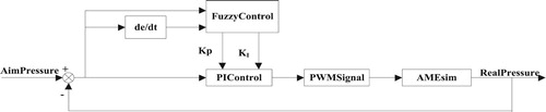
Figure 6. Membership function of input variable e.
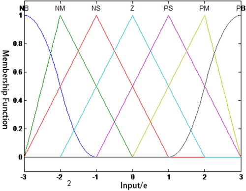
Table 1. Fuzzy rules for Kp and KI (Leng et al., Citation2019).
5. Simulation test results
The characteristics of the EHB system were analyzed and studied by AMEsim™ software, and the hydraulic-pressure-following control algorithm was analyzed on the MATLAB®/Simulink® platform. Based on the real-time status of the complex braking conditions of vehicles (Chen et al., Citation2019), and sub-models such as for the brake master cylinder, brake wheel cylinder, and solenoid valve, control of the EHB system was established by AMEsim and Simulink software. Afterwards, the liquid-pressure-following control algorithm was detected by a test bench, and the control algorithm was also optimized. The co-simulation model was established based on AMEsim and Simulink ansofts, as depicted in Figure . Two input signals were setup. The first input signal was a triangular wave with a period of 10 s and amplitude 3 MPa. The simulation results for the triangular wave are shown in Figure .
Figure 7. Co-simulation model of the EHB system.
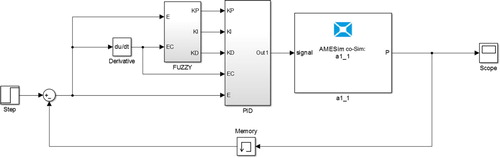
Figure 8. Triangular-wave-following response.
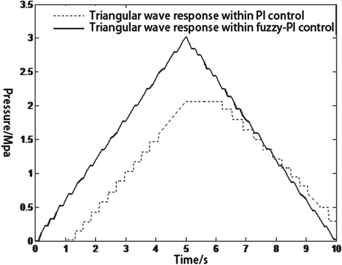
Figure indicates that, using only PID control of the cylinder pressure of the EHB system, there is a crawling phenomenon due to friction in the boosting process, and the amplitude is 2 MPa. At the same time, a dead zone of 1 s exists from 5 to 6 s, and the pressure-following effect is not ideal. The cylinder hydraulic pressure of the EHB system is controlled by fuzzy PI, which can restrain the crawling phenomenon during the boosting pressure process, the amplitude reaches 3 MPa and the dead zone phenomenon disappears, which can follow the target triangular wave better and respond quickly.
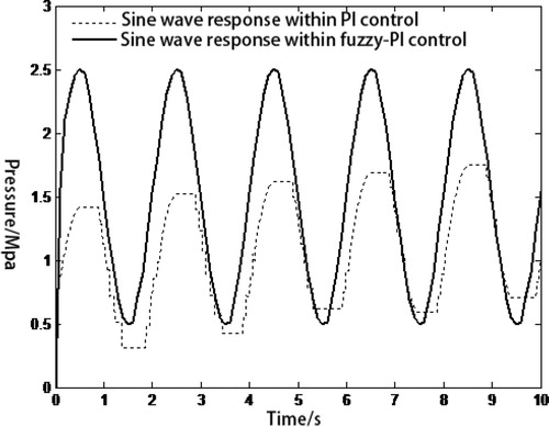
The input signal of the EHB system was a sine wave of amplitude 1 MPa, a mean value of 1.5 MPa, and a frequency of 0.5 Hz. The simulated sine-wave-following response, as depicted in Figure , indicates that the effect of fuzzy-PI control on the cylinder hydraulic pressure of the EHB system is better than PID control, as the root-mean-square-error of the fuzzy-PI control is 0.1523 MPa, while that of the pure PID control system is 0.5738 MPa.
Figure 9. Sine-wave-following response.
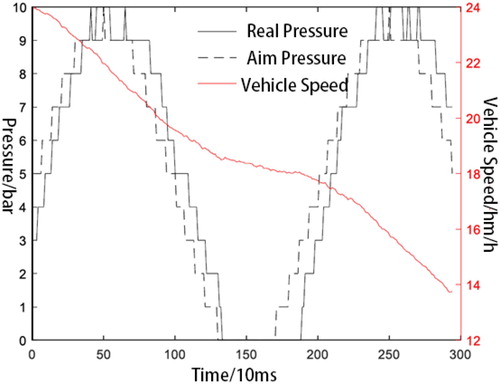
In order to verify the correctness of the hydraulic-pressure-following control method of the EHB system based on the fuzzy-PI control method, the experimental vehicle was modified accordingly. The vacuum booster of the test vehicle was replaced by the EHB system, and a pressure build-up test of EHB system was carried out and analyzed. With an initial braking speed of 30 km/h, the target hydraulic pressure input is signals of 1, 5 and 10 MPa steps, and sine waves of amplitude 0.5 and 2 MPa and means of 0.5 and 2 MPa. The target hydraulic pressure with 1 and 5 MPa steps is shown in Figure . The target hydraulic pressure with 10 MPa steps is shown in Figure . The pressure curve of the sine wave is shown in Figure .
Figure 10. Target hydraulic pressure with 1 and 5 MPa steps.
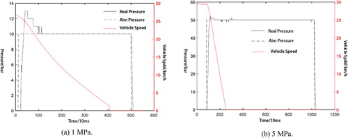
Figure 11. Target hydraulic pressure with 10 MPa steps.
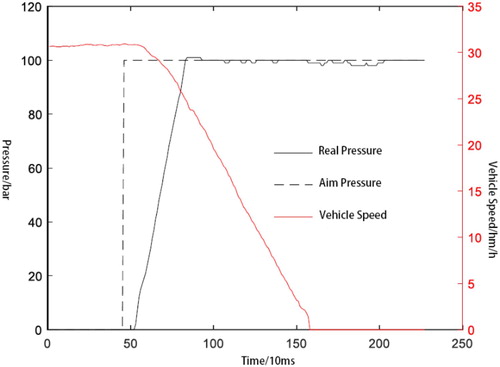
Figure 12. Pressure curve of sine wave.
Figures and show that there is a 10% overshoot in the EHB system under the low target hydraulic pressure requirement. Under the medium target hydraulic pressure requirement, the hydraulic pressure response time of the EHB system is the best, and under the high target hydraulic pressure requirement, the hydraulic pressure response time of the EHB system is longer. The step response test can simulate the driver’s driving condition when he stepped on the brake pedal instantaneously, and then the brake pedal is held down steadily. The above test results indicate that the hydraulic control strategy of the EHB system can meet the requirements of this kind of braking condition.
Figure shows that the dynamic response of the EHB system is better when the target hydraulic pressure is a sine wave, and the change trend of the actual hydraulic pressure is consistent with that of the target hydraulic pressure. The sinusoidal response test can simulate the driving condition of the driver repeatedly treading on and loosening pressure on the brake pedal. The test results show that the hydraulic control strategy of the EHB system can meet the requirements of this kind of braking condition.
6. Conclusions and future work
This paper analyzes the nonlinear friction of the transmission mechanism of an EHB system, establishes a corresponding simplified model, adds a chatter signal as friction compensation, and establishes a fuzzy-PI control method to follow different target hydraulic pressures. The co-simulation model is established by AMEsim and Matlab/Simulink software, which is used to check on the feasibility of the control method, and the control method is also simulated and analyzed.
The hydraulic responses of the cylinder to input signals of step, triangular wave and sinusoidal wave forms are simulated, respectively. The root-mean-square error of sinusoidal signal tracking is 0.1523 MPa, and the tracking effect is good. A corresponding vehicle test is carried out that can validate the correctness of the hydraulic-pressure-following control method for the EHB system, in which step target pressures of 1, 5 and 10 MPa are input. The error value is less than 10% for the actual hydraulic pressure response of 1 MPa, and the test results are excellent. In future work, we plan to verify the reliability of the proposed control method further, and find possible problems through long-term vehicle road tests and storage of CAN messages.
Acknowledgements
The authors would like to thank the anonymous reviewers for their helpful comments and suggestions to improve the manuscript.
Disclosure statement
No potential conflict of interest was reported by the authors.
Additional information
Funding
Reference
- Baghban, A., Jalali, A., Shafiee, M., Ahmadi, M. H., & Chau, K. W. (2019). Developing an ANFIS-based swarm concept model for estimating the relative viscosity of nanofluids. Engineering Applications of Computational Fluid Mechanics, 13(1), 26–39. https://doi.org/10.1080/19942060.2018.1542345
- Castillo, J. J., Cabrera, J. A., Guerra, A. J., & Simón, A. (2016). A novel electrohydraulic brake system with tire–road friction estimation and continuous brake pressure control. IEEE Transactions on Industrial Electronics, 63(3), 1863–1875. https://doi.org/10.1109/TIE.2015.2494041
- Chen, Q. P., Sun, H. Y., Wang, N., Niu, Z., & Wan, R. (2020). Sliding mode control of hydraulic pressure in electro-hydraulic brake system based on the linearization of higher-order model. Fluid Dynamics & Materials Processing, 16(3), 513–524. https://doi.org/10.32604/fdmp.2020.09375
- Chen, Q., Wu, M., Kang, S., Liu, Y., & Wei, J. (2019). Study on cavitation phenomenon of twin-tube hydraulic shock absorber based on CFD. Engineering Applications of Computational Fluid Mechanics, 13(1), 1049–1062. https://doi.org/10.1080/19942060.2019.1666035
- Kong, X., Wang, Y., & Jiang, S. (2010). Friction chatter-compensation based on stribeck model. Journal of Mechanical Engineering, 46(5), 68–73. https://doi.org/10.3901/JME.2010.05.068
- Leng, J. W., Pan, P., Xu, Z. K., Wang, T., & Jin, L. (2019, August 11–14). Design of low speed controller for traveling wave ultrasonic motor. 22nd International Conference on Electrical Machines and Systems (ICEMS), Harbin, China (pp. 1–5). IEEE. https://doi.org/10.1109/ICEMS.2019.8921667
- Li, X., Chang, S., & Gong, X. (2015, December 19–20). Modeling of a new brake by wire system based on the direct-drive electro-hydraulic brake unit. 2015 IEEE Advanced Information Technology, Electronic and Automation Control Conference (IAEAC), Chongqing, China (pp. 211–215). https://doi.org/10.1109/IAEAC.2015.7428549
- Liu, T., Yu, Z., Xiong, L., Han, W., & Wang, J. (2017). Anti-lock braking control for integrated electronic hydraulic braking system. Automotive Engineering, 39(7), 767–774. https://doi.org/10.19562/j.chinasae.qcgc.2017.07.007
- Oshima, T., Fujiki, N., Nakao, S., Kimura, T., Ohtani, Y., & Ueno, K. (2011). Development of an electrically driven intelligent brake system. SAE International Journal of Passenger Cars Mechanical Systems, 4(1), 399–405. https://doi.org/10.4271/2011-01-0568
- Salih, S. Q., Allawi, M. F., Yousif, A. A., Armanuos, A. M., Saggi, M. K., Ali, M., & Chau, K. W. (2019). Viability of the advanced adaptive neuro-fuzzy inference system model on reservoir evaporation process simulation: Case study of Nasser Lake in Egypt. Engineering Applications of Computational Fluid Mechanics, 13(1), 878–891. https://doi.org/10.1080/19942060.2019.1647879
- Si, Y., Zhu, Y., Zou, R., Guo, F., & Wang, J. (2014). Current situation and development trend of automobile diesel standards in China. Chemical Engineering of Oil & Gas, 43(1), 82–86. https://doi.org/10.3969/j.issn.1007-3426.2014.01.017
- Wei, H., Lu, X., Yu, L. I., Yimeng, H., & Zhuoping, Y. U. (2017). Yaw stability control strategy based on integrated-electro-hydraulic brake system. Journal of Mechanical Engineering, 53(24), 161–169. https://doi.org/10.3901/JME.2017.24.161
- Yang, B., & Han, B. (2017). Control strategy model and simulation study of automobile electronically controlled hydraulic braking system. Automation and Instrumentation, 37(3), 87–90. https://doi.org/10.14016/j.cnki.1001-9227.2017.03.087
- Yang, B., & Wu, X. (2017). Identification of braking intention of EHB system based on fuzzy logic. Process Automation Instrument, 38(9), 25–28. https://doi.org/10.16086/j.cnki.issn1000-0380.201709006
- Yong, J., Gao, F., Ding, N., & He, Y. (2017). Design and validation of an electro-hydraulic brake system using hardware-in-the-loop real-time simulation. International Journal of Automotive Technology, 18(4), 603–612. https://doi.org/10.1007/s12239-017-0060-2
- Yu, Z., Han, W., & Xu, S. (2017). Overview of the development of hydraulic control of electronic hydraulic braking system. Journal of Mechanical Engineering, 53(14), 1–15. https://doi.org/10.3901/JME.2017.14.001
- Yuan, J., Zhu, S., Zhou, Y., Lu, Z., Ma, J., & Deng, X. (2018). Experimental of tractor front axle hydro-pneumatic suspension system vibration response characteristic. Journal of Mechanical Design, 35(2), 48–55. https://doi.org/10.13841/j.cnki.jxsj.2018.02.009.
- Yuan, W., Li, L., Zhang, D. G., & Hong, J. Z. (2016). New method for oblique impact dynamics research of a flexible beam with large overall motion considering impact friction force. Acta Mechanica Sinica, 32(4), 720–730. https://doi.org/10.1007/s10409-016-0576-0
- Zhao, X., Li, L., Song, J., Li, C., & Gao, X. (2016). Linear control of switching valve in vehicle hydraulic control unit based on sensorless solenoid position estimation. IEEE Transactions on Industrial Electronics, 63(7), 4073–4085. https://doi.org/10.1109/TIE.2016.2541080
- Zhao, Y., & Collins, E. G. (2003). Fuzzy PI control design for an industrial weigh belt feeder. IEEE Transactions on Fuzzy Systems, 11(3), 311–319. https://doi.org/10.1109/TFUZZ.2003.812686