
 ?Mathematical formulae have been encoded as MathML and are displayed in this HTML version using MathJax in order to improve their display. Uncheck the box to turn MathJax off. This feature requires Javascript. Click on a formula to zoom.
ABSTRACT
A Tesla valve is a kind of micro-valve without moving parts. Due to the great difference between the reverse and forward flow, the Tesla valve is often used in passive fluid control devices. However, most of the current Tesla valve components are optimized and designed based on asymmetric structures. In this study, a Tesla valve pipe system model with symmetric structure is proposed. The characteristics of fluid flow and pressure drop were studied by finite element method and dimensional analysis. First, the pressure drop characteristics of symmetric and asymmetric Tesla valves with different Reynolds number are considered. The results show that the better the symmetry, the better the one-direction flow characteristics of Tesla valve system. Afterwards, through parametric analysis, computational fluid dynamics was used to verify flow characteristics of completely symmetrical Tesla valve system. The shunt angle, shunt pipe diameter and number of valves have significant effects on the pressure drop characteristics of the system. Eventually, based on numerical simulation results, by using the dimensional analysis method, the modification parameter was introduced to obtain the scaling law
between the pressure drop and other parameters of the completely symmetrical Tesla valve piping system.
1. Introduction
No-moving-parts check valves (NMPVs) can effectively realize passive flow control in microchannels. Their unique structural designs allow NMPVs to exhibit pressure drop characteristics related to the flow direction and create a ‘fluid diode’ effect; that is, the flow resistance in one direction is higher than that in the other flow direction. Compared with the traditional check valve with moving parts, NMPVs have the advantages of no moving parts and easy expansion and manufacturing, which can effectively realize passive flow control. They also have advantages in conveying solutions with large particles or cellular substances. Therefore, the application in microfluidic (Truong & Nguyen, Citation2003; Wang et al., Citation2014; Zhang et al., Citation2007), biotechnology equipment (Forster et al., Citation1995), high-pressure hydrogen energy decompression (Qian, Chen, et al., Citation2019; Qian, Wu, et al., Citation2019), and other fields has attracted extensive attention. Common NMPVs are the nozzlediffuser valve (Stemme & Stemme, Citation1993), heart-shaped valve (Fadl et al., Citation2009), and Tesla valve (Forster et al., Citation1995; Jin et al., Citation2018; Martin, Citation2009; Nikola, Citation1920; Nobakht et al., Citation2013; Pingen et al., Citation2008; Truong & Nguyen, Citation2003; Wang et al., Citation2014; Zhang et al., Citation2007). Among them, Tesla valve, also known as a valve conduit, is a one-direction flow check valve component with no-moving-parts. It was first invented by Nikola Tesla in 1920 and applied to turbines, which can significantly improve its conveying efficiency (Nikola, Citation1920).
Since the Tesla valve component was proposed, the research on the flow characteristics of Tesla valves has been well developed, and its one-direction flow characteristics largely depend on the geometric structure and Re number. Therefore, it is highly significant to study the effects of the geometric parameters and fluid flow state on the flow characteristics of Tesla valves. In 1995, Forster et al. experimentally studied the pressure drop characteristics of Tesla valve at laminar flow (Re<300), and proposed the diodicity number (Di) to measure the one-direction flow performance of Tesla valve for the first time (Forster et al., Citation1995). The greater the Di number, the better the one-direction flow characteristics of Tesla valve. The results show that the Di number of the T45-R Tesla valve (shunt angle of ) increases linearly with the flow rate. In 2003, Truong et al. studied the pressure drop characteristics of a single Tesla valve under laminar flow (
) through numerical simulations and determined the optimal design parameters for the first time, including the shunt angle and straight pipe length (Truong & Nguyen, Citation2003). Subsequently, Gamboa et al. optimized the shape of a micropump with the Tesla valve proposed by Forster based on two-dimensional, steady, laminar flow (
) simulations with ANSYS FLOTRAN and verified the simulation results through experiments (Gamboa et al., Citation2005). In 2007, Zhang et al. carried out three-dimensional numerical simulations of Telsa valve and proposed a geometric relationship through optimization research. The results showed that the greater the aspect ratio of the Tesla valve pipe, the better the flow characteristics of the system, that is, the greater the value of Di number (Zhang et al., Citation2007). Porwal et al. analyzed the flow and heat transfer control of multi-stage Tesla valves under laminar flow (
) in detail (Porwal et al., Citation2018).
The above results show that the geometric configuration has a significant influence on the flow characteristics of the Tesla system. However, the fluid flow state was still laminar, that is, the Reynolds number . Based on the inertia of motion, the fluid in the Tesla valve piping system undergoes fluid splitting, flow separation, and local distortion at the mutation location, and then the vortex energy was dissipated. Considering this feature, the Re number at the valve inlet cannot fully represent the overall flow pattern of the whole Tesla valve system. Hence, Thompson et al. adopted the
,
,
, and other Reynolds-averaged Navier–Stokes (RANS) turbulence models for numerical simulation research on the GMF Tesla valve (Gamboa et al., Citation2005) and compared the numerical results with the experimental results (Thompson et al., Citation2013). The results showed that the
model could not reflect the flow characteristics of the Tesla valve well. Recently, Nguyen et al. preliminarily considered the instability mechanism of the fluid flow state of a Tesla valve system under laminar flow (
) and turbulent flow (Re>2000) (Nguyen et al., Citation2021).
As far as existing research is concerned, most studied the flow characteristics of Tesla valve system with asymmetric structure under laminar flow. However, these kinds of researches have common obvious shortcomings: (a) Lack of more detailed analysis and research on the influence of geometric parameters; (b) There is little research on the characteristics of Tesla valve systems in turbulent flow (); (c) The one-direction flow characteristics of the traditional asymmetric Tesla valve system is not yet perfect; (d) For the Tesla valve system, there is still a lack of scaling law relationships between parameters, which is not conducive to practical engineering applications. Therefore, considering the above issues, it is of great significance to design a novel Tesla valve system that can significantly improve its one-direction flow characteristics. In addition, further analysis of the scaling law between the parameters affecting the flow characteristics will accelerate their application in the fields of biomedicine, MEMS, and micro-nano heat transfer.
Given that, in this paper, we have been inspired by the geometrically symmetric Y-shaped channel system, which has better flow separation and heat transfer characteristics. The Tesla valve pipe system with completely symmetric structure is proposed. Then, through parametric analysis, including the geometry, Re number, shunt angle, shunt pipe diameter, and number of valve pairs, etc., computational fluid dynamics (CFD) is used to verify the flow characteristics of the Tesla valve. Eventually, combined with the finite element numerical results, the dimensional analysis is used to determine the scaling law between the pressure drop of the completely symmetric Tesla system and other parameters.
2. Problem description
2.1. Working principle of Tesla valve
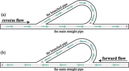
The Tesla valve system is mainly composed of two parts: a main straight pipe section and a branch pipe section (see Figure ). In Figure (a), at a fixed flow rate, when the fluid flows through the first bifurcation in the reverse direction, part of the fluid can easily flow along the branch, due to inertia of fluid, after which it flows out to the next bifurcation and collides with the flow from the main pipe section, forming a complex flow field with local turbulence. This results in huge energy dissipation of vortexes and increases the local pressure loss. However, when the flow is in the forward direction (see Figure (b)), the fluid is cannot easily flow along the branch, and the resistance force of the branch fluid to the main flow is much smaller. Thus, the local pressure loss is relatively small. It is precisely because of the existence of the branch pipe section that the flow distributions of the reverse and forward flow of the fluid are significantly different, which is a main feature of the one-direction flow of the Tesla valve.
Figure 1. Geometric structural diagram of Tesla valve piping system. (a) Reverse flow; (b) Forward flow.
2.2. Evaluation indices of Tesla valve performance
Generally, the performances of Tesla valves can be measured by the dimensionless pressure drop ratio (Forster et al., Citation1995), throttling efficiency (Nikola, Citation1920), and Hagen number (Awad, Citation2013; Nguyen et al., Citation2021).
The pressure drop ratio, also known as the diodicity number, is defined as the ratio of the pressure drop between the reverse and forward flow at a certain flow rate. It can be expressed by the following formula:
(1)
(1) where
,
,
,
,
,
,
, and
are the reverse total pressure drop, the forward total pressure drop, the total pressure at the reverse inlet, the total pressure at the reverse outlet, the total pressure at the forward inlet, the total pressure at the forward outlet, the reverse flow rate, and the forward flow rate, respectively.
The throttling efficiency can also reflect the performance of the Tesla valve. It is defined as the relative size of the flow rate when the fluid flows in the reverse and forward directions under a certain additional pressure drop. The formula is as follows:
(2)
(2) To a certain extent, the pressure drop ratio and throttling efficiency of the Tesla valve are equivalent, as both can reflect the one-direction flow characteristics of the Tesla valve.
In addition, the Hagen number is expressed as a dimensionless pressure gradient, which can also reflect the pressure drop characteristics of the reverse flow Tesla valve system. Its formula is as follows:
(3)
(3) where L, D, ρ, and μ are the total flow length, characteristic length, fluid density, and hydrodynamic viscosity, respectively.
In this work, the pressure drop ratio Di and Hagen number Hg are selected as the important parameters to measure the pressure drop characteristics of the Tesla valve.
2.3. Symmetric and asymmetric units of Tesla valves
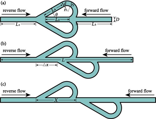
Figure shows a schematic diagram of the geometric model of the Tesla valve unit piping system. The specific geometric information is as follows: the entrance section was 20 mm, the middle section
was 20 mm, the exit section
was 20 mm, the diversion section
was 20 mm, the diameter of the main straight pipe section D was 2 mm, the branch pipe section diameters d were 1, 2, and 3 mm, and the shunt angle θ was
–
. The radii of the inner and outer arcs of the shunt pipe section can be expressed as follows:
(4)
(4)
is the horizontal distance difference from the start of the upper and lower branches. And X is the horizontal distance difference from the start and the end of the upper branches. In the following sections, when
, the Tesla valve system is referred to as a completely symmetric structure (see Figure (a)). Similarly, when
, the system has a partially asymmetric structure (see Figure (b)). And, when
, the system has a completely asymmetric structure (see Figure (c)).
Figure 2. Schematic diagram of the symmetric and asymmetric configuration of the Tesla valve system. (a) Completely symmetric, (b) partially asymmetric, and (c) completely asymmetric.
3. Numerical methods and validation
The phenomenon of fluid flow exists in nature and various engineering fields. All these processes can be governed by fundamental physical laws, such as conservation of mass, conservation of momentum, and conservation of energy. Computational fluid dynamics (CFD), which has significant advantages when dealing with such problems, has become a powerful tool to analyze engineering problems in various fields. In particular, it is suitable for experimental and theoretical research on complicated issues (Cheng et al., Citation2021; Ghalandari et al., Citation2019; Salih et al., Citation2019). In this work, we use CFD to analyze the pressure drop characteristics of Tesla valves and explore the flow characteristics of symmetrical and asymmetric Tesla valves.
3.1. Governing equations and boundary conditions
The fluid flow behavior in a Tesla valve is typical internal flow that involves flow with strong curvature, separated flow, and jet flow. Thus, the flow is turbulent. For this type of flow through the pipe bend, the model tends to ignore the flow in the buffer zone near the wall and cannot accurately calculate the adverse pressure gradient and strong curvature flow field of the flow (Menter, Citation1993; Xu et al., Citation2008). The
model gives more accurate results when solving these types of problems. Therefore, the RANS
turbulence model was selected in this study, and the finite element software COMSOL Multiphysics was used to obtain the physical fields.
The governing equations of the model include the incompressible continuity equation, modified Navier–Stokes equation, and four auxiliary equations for the turbulent flow energy k and turbulent velocity ω, expressed as follows:
(5)
(5)
(6)
(6)
(7)
(7)
(8)
(8)
(9)
(9) In addition, the boundary condition of the Tesla valve wall is a wall function with no flux, and the fluid is incompressible. The inlet was set as the boundary condition of the flow velocity, the outlet pressure was zero, and the surrounding conditions were non-slip conditions. The fluid domain was water with a density of 1000 kg/m
and viscosity of
Pa·s.
3.2. Verification of numerical method
First, the applicability of the finite element numerical method was verified. Figure shows results from the literature (Truong & Nguyen, Citation2003) and the numerical simulation in this paper. The results show that the numerical method could simulate the flow characteristics of Tesla valve systems well.
Figure 3. Validation of the numerical simulations in this paper with literature results (Truong & Nguyen, Citation2003).
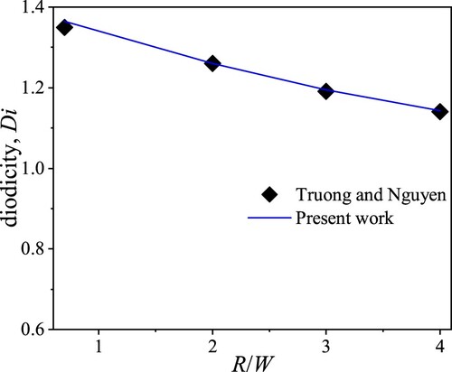
Figure shows the grid distribution of the numerical simulations. To reduce the running time and improve the accuracy, a structured grid was used in the main straight pipe section, and an unstructured grid was used in the branch pipe section. The grid was encrypted at the boundary layer and local shunt flow region. According to Table , grids A, B, C, D, and E were used to check the independence of the solution. As the number of grid elements increased, the sensitivity of the pressure drop ratio Di to the number of grid elements decreased. When the number of grid elements increased from 44,398 to 55,135, the sensitivity of Di decreased by 1.90%, which was negligible. Thus, Model-D was selected for the simulations.
Figure 4. Computational grid distribution.
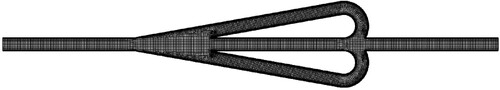
Table 1. Grid independence verification.
4. Results and discussion
4.1. Flow field and pressure drop changes of symmetric and asymmetric Tesla valves
4.1.1. Streamline distribution
Figure shows the velocity vector of the symmetric and asymmetric Tesla valve system. As shown in Figure , the black arrow reflects the direction of fluid flow; In the local enlarged view, the streamline results can be clearly seen, which are represented by white lines. Besides, the velocity magnitude in different cases can be well expressed by color bar, and vortex structure can also be observed at the local mutation position. By comparing the color bars in Figure (a–c), the better the symmetry, the greater the velocity magnitude in the reverse flow, that is, the greater the pressure drop. However, in forward flow, the symmetrical and asymmetrical Tesla valve systems have almost the same speed magnitude. In addition, the reverse flow could more easily form vortex structures than the forward flow at the local mutation position for the same configuration Tesla valve pipe system under the same flow rate.
Figure 5. Velocity vector of Tesla valve system (): (a) completely symmetric, (b) partially asymmetric, and (c) completely asymmetric.
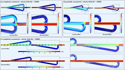
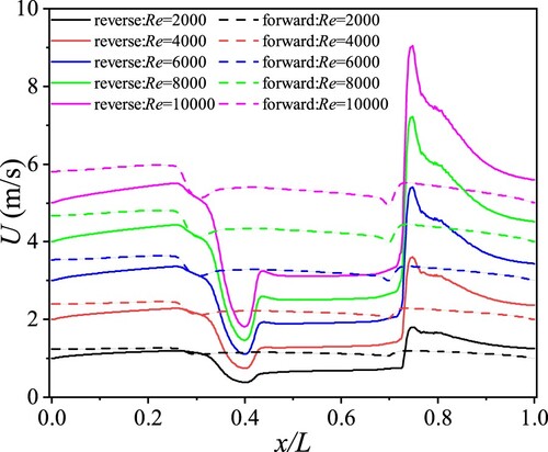
Figure shows the velocity distribution at the middle line of the main straight pipe section of the completely symmetric Tesla valve system. The solid line shows the reverse flow, and the dotted line shows the forward flow. The results show that for the same flow rate, the fluid velocity changed more dramatically at the branch pipe section in the reverse flow than in the forward flow. Meanwhile, the velocity increased with the increase in the Reynolds number Re at the same position.
Figure 6. Velocity distribution on the center line of completely symmetric Tesla valve system.
From the above simulation results, it can be concluded that symmetrical structure can improve the one-direction flow characteristics of Tesla valve system. It can increase the pressure drop of the fluid in the reverse flow. What's more, fluid inertia is the main factor affecting the one-direction flow characteristics of Tesla valve system. Therefore, an appropriate increase of fluid velocity may be beneficial to improve pressure drop characteristics.
4.1.2. Pressure drop variations
Figure shows the change in the pressure drop ratio Di. With the increase in the Reynolds number Re, the pressure drop ratio Di of both the symmetric and asymmetric Tesla valve systems increased. The Reynolds number Re increase was achieved by changing the inlet velocity. Varying the viscosity and density of the fluid is also a feasible way to change Reynolds number Re. For the same Reynolds number Re, the Di value of the symmetric Tesla valve system was much larger than that of the asymmetric Tesla valve system. That is, the higher the symmetry was, the greater the pressure drop ratio became. After the symmetry was broken, the pressure drop ratio decreased. Therefore, the completely symmetric Tesla pipe system had better one-directional flow characteristics.
Figure 7. Variation of Di in symmetric and asymmetric Tesla valve systems.
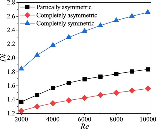
Figure shows the change of the Hagen number Hg in the symmetric and asymmetric Tesla valve systems. Figure (a,b) shows reverse flow and forward flow respectively. As can be seen form Figure (a), under the same flow conditions, namely the same Re number, the Hg number of the symmetric Tesla valve system was higher than that of the asymmetric Tesla valve system for reverse flow. In addition, for the Tesla valve system of the same configuration, the Hg value increases with the increase of Re number. Similarly, it can be seen from Figure (b) that in the forward flow, Hg number increases with the increase of Re number. However, there is little difference between the Hg values of the symmetrical and asymmetric Tesla valve systems under the same flow conditions.
Figure 8. Variation of Hg in symmetric and asymmetric Tesla valve systems: (a) reverse flow and (b) forward flow.
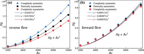
Furthermore, when the Reynolds number was large (Re>2000), the Hg and Re values of the reverse and forward flow were related as follows , which is consistent with the conclusion reported previously (Nguyen et al., Citation2021).
4.2. Parameter design of Tesla valve unit
4.2.1. Effect of shunt angle
In the previous section, we determined that the one-direction flow characteristics of the completely symmetric Tesla valve were better than those of the asymmetric structure. In the following sections, we will consider the influence of the other parameters on the completely symmetric Tesla valve system. First, the influence of the shunt angle on the pressure drop ratio of the Tesla valve system is considered. The change of the shunt angle θ () increased by
each time, and the variation of the pressure drop ratio Di is shown in Figure .
Figure 9. Effect of shunt angle θ on Di number.
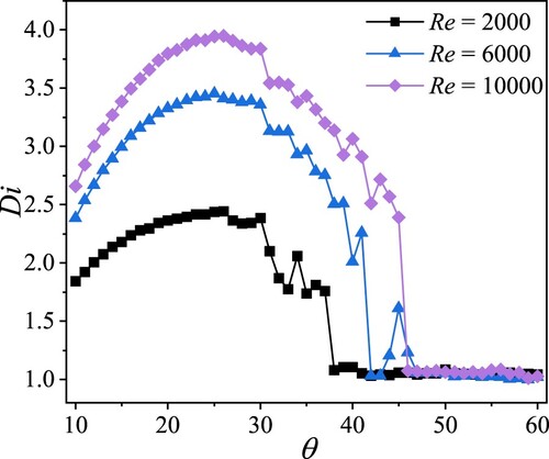
The results showed that under the same flow conditions, with the increase in the shunt angle θ, the pressure drop ratio Di of the Tesla valve first increased and then decreased. At a small angle (), the system characteristics were relatively good. However, when the shunt angle was large (
), the system pressure drop characteristics deteriorated.
4.2.2. Effect of shunt pipe diameter
As shown in Figure , when the shunt angle , the system pressure drop ratio Di was the maximum. Next, the shunt angle of the symmetric Tesla valve system was set to
, and the influence of the shunt pipe diameter d was further considered.
Figure shows the velocity contours of the Tesla valve system for different shunt pipe diameters d (). In Figure , the black arrow reflects the direction of fluid flow; In the local enlarged view, the streamline results can be clearly seen, which are represented by white lines. In addition, the velocity magnitude in different cases can be well expressed by color bar.
Figure 10. Velocity contours of Tesla valve system for different shunt pipe diameters d (): (a)
, (b)
, and (c)
.
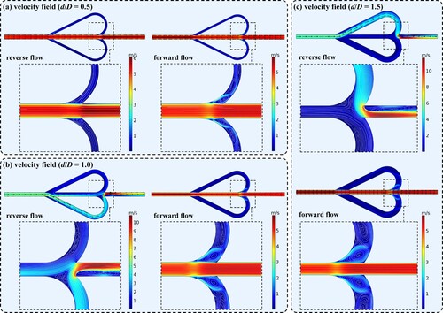
In the reverse flow, the larger the shunt pipe diameter d, the greater the maximum velocity of the reverse flow of the Tesla valve system. For these three kinds of Tesla valve systems, compared with the forward flow, the reverse flow was more likely to form the energy dissipation of vortex structure in the shunt pipe section, thus having a better ‘fluid diode’ effect.
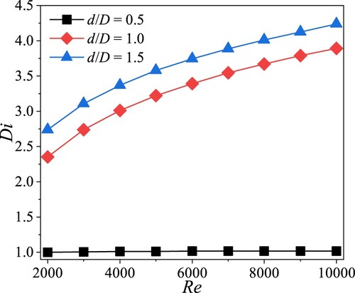
Figure shows the effect of the shunt pipe diameter d on the system pressure drop ratio Di. The results showed that for three Tesla valve systems with different shunt pipe diameters d, the pressure drop ratio Di increased with the increase in Re, which is consistent with the conclusion obtained in Section 4.2. Besides, under the same flow conditions, the pressure drop ratio of the system increased with the increase in the shunt pipe diameter d. Taking into account the processing difficulty of the actual pipeline system, it is more appropriate to choose the same diameter of the branch pipe and the main pipe.
Figure 11. Effect of shunt pipe diameter d on Di number.
4.3. Result analysis of Tesla multi-valve system
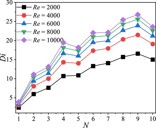
4.3.1. Effect of number of valve pairs
Next, we consider the effect of the number of valve pairs N. Figure shows the variation of Di with the number of valve pairs N. The results showed that under the same flow rate, for the symmetric pipe, the pressure drop ratio Di increased with the increase in the number of valve pairs N. When the number of valve pairs N was the same, the larger the Reynolds number Re was, the larger the Di number became.
Figure 12. Effect of number of valve pairs N on Di number.
4.4. Flow scaling law in Tesla valve pipe based on dimensional analysis
To process and analyze the numerical simulation results obtained in the previous section, dimensional analysis was performed. Based on the theory of dimensional analysis (Bridgman, Citation1922; Sun, Citation2016), there are six parameters for the liquid flow in a smooth circular pipe. The basic dimensions of these parameters are L, M, and T, as shown in Table .
Table 2. Dimensions of physical quantities.
As a result of this scaling, the number of dimensionless variables in this problem reduces to 6−3 = 3 groups, shown as follows:
(10)
(10) where the exponents
,
, and
can be determined by the dimensionless conditions
, i.e.
(11)
(11) Hence,
,
, and
. Solving these equations, we determined that
,
and
. These are related to the first dimensionless variable
, which is the Euler number:
(12)
(12) Similarly, we determined that
,
, and
, and the second dimensionless variable
is
(13)
(13) Finally, we found that
,
, and
, and the third dimensionless variable
is
(14)
(14) where
has also been rewritten as
, which is the dimensionless Reynolds number. This can well reflect the flow state of the fluid in the pipe.
From the Buckingham Pi theorem (Bridgman, Citation1922; Buckingham, Citation1914), the pressure drop can be replaced by
=
, as follows:
(15)
(15) Equation (Equation15
(15)
(15) ) is a universal scaling law for fluid flow in smooth circular tubes, where the function
can be determined either experimentally or numerically.
Next, according to the flow state in a smooth pipe, the force balance relationship in the smooth straight pipe system is considered. The shear stress , pressure p, pipe length L, and pipe diameter D satisfy the following equation:
(16)
(16) Furthermore, the dimensionless drag coefficient λ is introduced, and the relationship is as follows:
(17)
(17) where
is the average velocity of the section. By substituting Equation (Equation17
(17)
(17) ) into Equation (Equation16
(16)
(16) ), we obtain the following formula:
(18)
(18) In 1911, Blasius (Citation1913) studied a large amount of experimental data and obtained the formula of the turbulent drag coefficient λ in smooth circular tubes:
(19)
(19) Substituting Equation (Equation19
(19)
(19) ) into Equation (Equation18
(18)
(18) ) yields the following equation:
(20)
(20) By combining Equations (Equation16
(16)
(16) ) and (Equation20
(20)
(20) ), we obtain
(21)
(21) Therefore, we determine that the dimensional relation Equation (Equation15
(15)
(15) ) in a smooth circular straight pipe can be written as
(22)
(22) Further rearranging this, we obtain the following relationship between the dimensionless Euler number Eu, length–diameter ratio L/D, and Reynolds number Re:
(23)
(23) For the Tesla valve piping system with a branch (Figure ), the modification parameter α can be introduced, and Equation (Equation23
(23)
(23) ) can be further modified as follows:
(24)
(24) In Equation (Equation24
(24)
(24) ), when
, it corresponds to the smooth circular straight pipe system without branches. For the symmetric Tesla valve system proposed in this paper, α is a multi-factor parameter related to the shunt angle θ, pipe diameter d, and number of valve pairs N of the branch pipeline, namely,
.
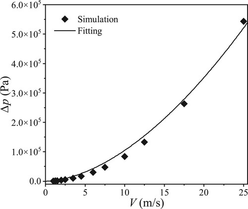
To verify whether the symmetric Tesla valve system with the branch pipes satisfied Equation (Equation24(24)
(24) ), the functional relationship between pressure drop
and velocity V of the Tesla valve unit was first obtained. The finite element simulation data were fitted, as shown in Figure . The results showed that the pressure drop
and velocity V satisfy
, which further proved the correctness of Equation (Equation24
(24)
(24) ).
Figure 13. Fitted curve of the simulation results, satisfying .
As the influence factors of the modification parameter α are too complicated, only the influence of the number of valve pairs N was considered, and the α in Equation (Equation24(24)
(24) ) was further improved.
Firstly, the dimensionless parameters L/D and in Equation (Equation24
(24)
(24) ) can be moved to the left side of the formula and further obtained
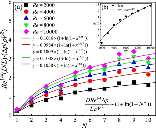
(25)
(25) Next, Figure (a) illustrates the variation of
with N at different Reynolds numbers. The results show that with the increase in the number of valve pairs N, the dimensionless parameter
of the system increased. Furthermore, by fitting the simulated data with the function
, the scaling law relation can be obtained as follows:
(26)
(26) where α is a parameter related to the Reynolds number Re. Thus, the relationship between α and Re was given in Figure (b). Naturally, based on data fitting, it is easy to derive that α and Re satisfy the function relation
.
Figure 14. Relationship between the dimensionless parameter and the number of valve pairs N for different Re.
Therefore, Equation (Equation27(27)
(27) ) can be further modified to obtain the scaling law between pressure drop
of the Tesla valve system with branches and other parameters as follows:
(27)
(27)
4.5. Discussion on the flow characteristics of the Tesla valve
By analyzing the data curves in Figures , and , we can draw the following conclusions. Under the same fluid state, the completely symmetrical Tesla valve system has better one-direction flow characteristics than the asymmetric Tesla valve system. This is because the symmetrical Tesla valve system has higher fluid resistance in reverse flow. Considering the reverse flow of the fluid in the symmetrical Tesla valve system, based on the inertia of the fluid, when the fluid in the branch pipe section collides with the incoming flow in the straight pipe section, due to the sudden reduction of the cross-sectional area of the pipe, complex flow fields such as local turbulence are formed, resulting in huge energy dissipation of vortexes.
In addition, the flow performance of Tesla valve can be significantly improved by reasonably designing the parameters such as shunt angle, shunt pipe diameter and the number of valve pairs. Additionally, the modified parameter α is obviously a multi-factor parameter related to the shunt angle, shunt pipe diameter and number of valve pairs. In this paper, we have obtained the scaling law considering number of valve pairs as the influence parameters, while the scaling law relationship of shunt angle and shunt pipe diameter as the influence parameters needs to be further considered in the future work.
5. Conclusion
This work focused on the flow characteristics of the Tesla valve piping system with symmetric structure. By using the finite element method, the effects of the geometry, Reynolds number Re, shunt angle θ, shunt diameter d, and number of valve pairs N on the pressure drop characteristics of the system were studied in detail. The fluid flow scaling law of the Tesla valve system was determined based on dimensional analysis theory. The main conclusions of this research are as follows:
For the symmetric and asymmetric Tesla valve piping system, the higher the symmetry was, the greater the pressure drop ratio Di of the system became. After the symmetry was broken, the pressure drop ratio Di decreased.
When the Reynolds number was large (Re>2000), the Hagen number Hg and Reynolds number Re of the forward flow and reverse flow of the symmetric Tesla valve system satisfied
.
The shunt angle θ had a greater effect on the pressure drop ratio Di of the Tesla valve system. When
With the increase in the branch pipe diameter d, the system pressure drop ratio Di also increased. When d<D, the pressure drop characteristics of the system were poor.
For the symmetric and asymmetric Tesla valve piping systems, under the same flow conditions, as the number of valve pairs N increased, the pressure drop ratio Di of the system also increased.
According to the data fitting, the scaling law of the pressure drop
Symmetric Tesla valve was proposed for the first time and the performance was successfully verified in this paper. Compared with the asymmetric Tesla valve system, the symmetric Tesla valve system exhibited excellent pressure drop performances. Furthermore, the fluid flow scaling law of the symmetric Tesla valve system was determined for the first time. However, there are still many problems that deserve further investigation. As to the symmetric Tesla valve, the effects of other parameters on flow characteristics are unknown, such as surface roughness, the radius and
of the curvature of branch pipes, etc. Moreover, the diameters of the symmetric Tesla valves in current research are on the millimeter scale. As the scale of the microchannel decreases, the viscous force plays a dominant role compared with the inertial force. How to significantly improve the one-direction flow characteristics of Tesla valve in micro-nano scale is extremely challenging, which will accelerate their application in the fields of biomedicine, MEMS, and micro-nano heat transfer.
Disclosure statement
No potential conflict of interest was reported by the author(s).
Additional information
Funding
References
- `Awad, M. M. (2013). Hagen number versus Bejan number. Thermal Science, 17(4), 1245–1250. https://doi.org/10.2298/TSCI1304245A
- Blasius, H. (1913). Das Aehnlichkeitsgesetz bei Reibungsvorgängen in Flüssigkeiten. Springer.
- Bridgman, P. W. (1922). Dimensional analysis. Yale University Press.
- Buckingham, E. (1914). On physically similar systems; illustrations of the use of dimensional equations. Physical Review, 4(4), 345–376. https://doi.org/10.1103/PhysRev.4.345
- Cheng, L., Zhu, Y. F., Band, S. S., Bahrami, D., Kalbasi, R., Karimipour, A., Jahangiri, M., Chau, K. W., & Mosavi, A. (2021). Role of gradients and vortexes on suitable location of discrete heat sources on a sinusoidal-wall microchannel. Engineering Applications of Computational Fluid Mechanics, 15(1), 1176–1190. https://doi.org/10.1080/19942060.2021.1953608
- Fadl, A., Zhang, Z., Geller, S., Tlke, J., Krafczyk, M., & Meyer, D. (2009). The effect of the microfluidic diodicity on the efficiency of valve-less rectification micropumps using lattice boltzmann method. Microsystem Technologies, 15(9), 1379–1387. https://doi.org/10.1007/s00542-009-0901-7
- Forster, F. K., Bardell, L., Afromowitz, M. A., Sharma, N. R., & Blanchard, A. (1995). Design, fabrication and testing of fixed-valve micro-pumps. Proceedings of the ASME Fluids Engineering Division.
- Gamboa, A. R., Morris, C. J., & Forster, F. K. (2005). Improvements in fixed-valve micropump performance through shape optimization of valves. Journal of Fluids Engineering, 127(2), 339–346. https://doi.org/10.1115/1.1891151
- Ghalandari, M., Koohshahi, E. M., Mohamadian, F., Shamshirband, S., & Chau, K. W. (2019). Numerical simulation of nanofluid flow inside a root canal. Engineering Applications of Computational Fluid Mechanics, 13(1), 254–264. https://doi.org/10.1080/19942060.2019.1578696
- Jin, Z. J., Gao, Z. X., Chen, M. R., & Qian, J. Y. (2018). Parametric study on tesla valve with reverse flow for hydrogen decompression. International Journal of Hydrogen Energy, 43(18), 8888–8896. https://doi.org/10.1016/j.ijhydene.2018.03.014
- Martin, H. (2009). A2 dimensionless numbers. Springer.
- Menter, F. (1993). Zonal two equation k-ω turbulence models for aerodynamic flows. AIAA 1993-2906, 23rd Fluid Dynamics, Plasmadynamics, and Lasers Conference. https://doi.org/10.2514/6.1993-2906
- Nguyen, Q. M., Abouezzi, J., & Ristroph, L. (2021). Early turbulence and pulsatile flows enhancediodicity of Tesla's macrofluidic valve. Nature Communications, 12(1), 2884. https://doi.org/10.1038/s41467-021-23009-y
- Nikola, T. (1920). Valvular conduit (U.S. Patent No. 1,329,559).
- Nobakht, A. Y., Shahsavan, M., & Paykani, A. (2013). Numerical study of diodicity mechanism in different tesla-type microvalves. Journal of Applied Research and Technology, 11(6), 876–885. https://doi.org/10.1016/S1665-6423(13)71594-3
- Pingen, G., Evgrafov, A., & Maute, K. (2008). A parallel Schur complement solver for the solution of the adjoint steady-state lattice Boltzmann equations: Application to design optimisation. International Journal of Computational Fluid Dynamics, 22(7), 457–464. https://doi.org/10.1080/10618560802238267
- Porwal, P. R., Thompson, S. M., Walters, D. K., & Jamal, T. (2018). Heat transfer and fluid flow characteristics in multistaged Tesla valves. Applied Mathematics and Mechanics, 73(6), 347–365.https://doi.org/10.1080/10407782.2018.1447199
- Qian, J. Y., Chen, M. R., Liu, X. L., & Jin, Z. J. (2019). A numerical investigation of the flow of nanofluids through a micro tesla valve. Journal of Zhejiang University-Science A: Applied Physics & Engineering, 20(1), 50–60. https://doi.org/10.1631/jzus.A1800431
- Qian, J. Y., Wu, J. Y., Gao, Z. X., Wu, A., & Jin, Z. J. (2019). Hydrogen decompression analysis by multi-stage tesla valves for hydrogen fuel cell. International Journal of Hydrogen Energy, 44(26), 13666–13674. https://doi.org/10.1016/j.ijhydene.2019.03.235
- Salih, S. Q., Aldlemy, M. S., Rasani, M. R., Ariffin, A. K., T. M. Yusoff Shah Tuan Ya, Al-Ansari, N., Yaseen, Z. M., & Chau, K. W. (2019). Thin and sharp edges bodies-fluid interaction simulation using cut-cell immersed boundary method. Engineering Applications of Computational Fluid Mechanics, 13(1), 860–877. https://doi.org/10.1080/19942060.2019.1652209
- Stemme, E., & Stemme, G. (1993). A valveless diffuser/nozzle-based fluid pump. Sensors and Actuators A: Physical, 39(2), 159–167. https://doi.org/10.1016/0924-4247(93)80213-Z
- Sun, B. H. (2016). Dimensional analysis and lie group. China High Education Press.
- Thompson, S. M., Jamal, T., Paudel, B. J., & Walters, D. K. (2013). Transitional and Turbulent Flow Modeling in a Tesla Valve. Proceedings of the ASME 2013 International Mechanical Engineering Congress and Exposition. https://doi.org/10.1115/IMECE2013-65526
- Truong, T. Q., & Nguyen, N. T. (2003). Simulation and optimization of tesla valves. Technical Proceedings of the 2003 Nanotechnology Conference and Trade Show.
- Wang, C. T., Chen, Y. M., Hong, P. A., & Wang, Y. T. (2014). Tesla valves in micromixers. International Journal of Chemical Reactor Engineering, 12(1), 397–403. https://doi.org/10.1515/ijcre-2013-0106
- Xu, J. L., Ma, H. Y., & Huang, Y. N. (2008). Nonlinear turbulence models for predicting strong curvature effects. Applied Mathematics and Mechanics, 29(1), 31–42. https://doi.org/10.1007/s10483-008-0105-z
- Zhang, S., Winoto, S. H., & Low, H. T. (2007). Performance simulations of tesla microfluidic valves. Proceedings of the 2007 First International Conference on Integration and Commercialization of Micro and Nanosystems. https://doi.org/10.1115/MNC2007-21107