
 ?Mathematical formulae have been encoded as MathML and are displayed in this HTML version using MathJax in order to improve their display. Uncheck the box to turn MathJax off. This feature requires Javascript. Click on a formula to zoom.
ABSTRACT
A feature of reverse circulation pneumatic down-the-hole (DTH) hammer drilling system is its ability to reduce the emission of respirable dust which is known to be harmful to drilling workers and equipment. The enhanced dust control performance of the drilling system requires better understanding and insight into the airflow behavior at the bottom of the borehole. To investigate the transportation and distribution of cuttings under various drilling parameters, and to evaluate the dust control performance, we conducted a series of simulations using computational fluid dynamics (CFD) multiphase modeling. Finite volume analysis was performed on a reverse circulation drill bit with an optimized structure reported in a previous study. The results show that increasing the input airflow rate can directly improve the dust control efficiency. The rising value in terms of cuttings feed concentration, rate of penetration (ROP), particle diameter, and specularity coefficient would decrease the dust control performance. Furthermore, the characteristics of the cutting distribution vary with the operating parameters and demonstrate the multiphase flow pattern in the RC-bit. This work may provide instructive insights into cutting transportation under various drilling parameters commonly considered in the drilling process and promote the development of dust suppression with efficient drilling operations.
1. Introduction
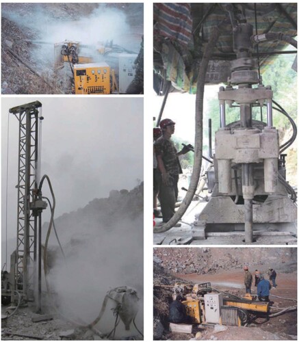
Pneumatic down-the-hole (DTH) hammer drilling is an advanced technique which provides mineral exploration and construction with many advantages. Some of these advantages stand out as an impressive rate of penetration (ROP) and efficient time utilization of cutting transportation (Zhang, Luo, Gan, et al., Citation2019). All these advantages offer economic benefits in comparison with conventional methods. However, pneumatic DTH hammer drilling is a task that is easily exposed to respirable dust (Leung et al., Citation2012), as shown in Figure , which can result in serious respiratory diseases (NIOSH, Citation1992). The government is also aware of the dangers of dust pollution and issued relevant decrees calling for enhanced research on dust prevention and control (SC, Citation2018). Thus, it is urgent to take immediate action to implement green mining and improve dust control performance at construction sites.
Figure 1. Dust explosion of conventional DTH air hammer drilling (left) and fine dust control performance of reverse circulation DTH air hammer drilling (right).
Many techniques and methods have been developed and applied to control the generation and spread of dust (Reed et al., Citation2008). Wet drilling is the most effective method, with dust control rates of up to 97%. However, the drawbacks of this method are evident, as they reduce the life of the drill bit and cause drill bit plugging (Page, Citation1991; Reed et al., Citation2008). Listak and Reed (Citation2007) addressed the potential of a newly designed water-separating sub to prevent premature drill bit failure during wet drilling. However, various new problems were encountered during the operation, such as maintaining of constant water flow and hole cave-in. Dust control for dry drilling works in a variety of ways, including drill decks (Organiscak & Page, Citation1999), shroud over the drill table (Organiscak & Page, Citation1999; Reed et al., Citation2008), and sealing of operator cabs (Andrew et al., Citation2005). However, equipment failure lead to a progressive deterioration in the effectiveness of dust control and requires maintenance. The application of reverse circulation DTH (RC-DTH) air hammer drilling has proven to be effective for dust suppression (Yin et al., Citation2015; Zhang, Luo, Gan, et al., Citation2019). This drilling method is independent of water resources at the construction site and has demonstrated a remarkably improved ROP. Meanwhile, dust suppression and equipment operation are synergistic, without the need for additional devices. The RC-DTH drilling system shows potential with low maintenance requirements and environmental friendliness in terms of industrial applicability.
A striking feature that distinguishes this drilling system from the conventional system is the central passage connecting the borehole bottom to the ground surface for cutting transport; whereby dust or cuttings can be sucked out through the central passage on account of the high-speed air flow formed by the RC-bit, and then collected far away from the construction site via the central through the passage of drill pipes and extended flexible discharge tube. The strong suction capacity of the RC bits indicates effective reverse circulation performance, which can be used to reduce and even eliminate dust leakage at the source.
The key part of inducing reverse circulation at the bottom of the borehole is the specially designed RC-bit with two types of nozzles. To enhance the reverse circulation performance, the primary consideration by researchers was to improve the geometrical parameters of the RC-bit based on a good understanding of the reverse circulation mechanism. However, based on extensive experiments, the traditional research method requires considerable amounts of RC bits, which is time-consuming and costly. Computational Fluid Dynamics (CFD) is a useful approach for understanding the properties of flow fields, especially in conditions where experiments cannot easily be conducted (Ghalandari et al., Citation2019). It has been proven to be a convenient, cost-effective, and efficient way to extract useful information for RC-bit design. Yin et al. (Citation2015) investigated the geometrical parameters of a suction nozzle through CFD simulations. Their study demonstrated that the suction capability of an RC bit is influenced by the number, elevation angle, and location of the suction nozzle, along with the existing optimal parameter values for the suction nozzle. Cao et al. (Citation2016) designed a novel RC-bit which establishes a special built-in structure to substitute the suction nozzle outlet. An annular slit forces the air flow to rise vertically along the central passage with no mutual interference, which results in a lower pressure zone within the drill pipes. Furthermore, Wu et al. (Citation2017) proposed a design based on a supersonic nozzle to enhance the suction capability. Luo et al. (Citation2016) studied the interaction between different parameters of an RC-bit and created an optimal design based on the CFD simulation results. Inspired by the minimum gas injection volume requirement, Zhang, Luo, Gan, et al. (Citation2019) optimized the geometric parameters of an RC-bit for large-diameter drilling, and the purposes of lower air consumption; whereby enhanced reverse circulation agreed well in both simulation and field tests.
The majority of current research is focused on the innovative design or optimal geometrical parameters using single-phase flow simulations; while there is little research considering the occurrence of the multiphase flow phenomenon in the bottom boreholes. For the purpose of multiphase flow analysis, CFD is widely used in chemical engineering (Mando & Yin, Citation2012; Mosavi et al., Citation2019; van Wachem et al., Citation1998), oil and gas drilling operations (Tang et al., Citation2021; Zhang, Luo, Fan, et al., Citation2019) or pneumatic conveying (Laín & Martin, Citation2012; McGlinchey et al., Citation2012). It mainly provides two methods, the Euler-Euler and Euler–Lagrange models, to investigate the details of solid flow behavior in the multiphase domain. Wang et al. (Citation2017) synthesized a series of numerical models for two-phase simulations. They indicated that the Euler–Lagrange method has limitations when the occupation of the dispersed phase is sufficiently large, such as in a fluidized bed (Peirano et al., Citation2002). The RC-DTH air hammer drilling technology is recognized for its high ROP (Peng et al., Citation2018). The high-volume fraction of the solid phase produced has a non-negligible effect on the flow field. For the dense dispersed phase, Larsen et al. (Citation1997) proposed an equation in which the concentration of cutting is expressed in terms of the ROP and cutting travel velocity. It was verified through CFD modeling work by Ozbayoglu et al. (Citation2013) and Epelle and Gerogiorgis (Citation2017). McGlinchey et al. (Citation2012) investigated the flow behavior under different expansion geometries using the Eulerian CFD model. The outcomes indicated that the presence of the solid phase influenced the recirculation in the pipeline, but no detailed laws were drawn. Lecreps et al. (Citation2014) found from detailed in-situ investigations of pneumatic conveying that solid particles are strongly correlated with wall stress. Furthermore, Wang et al. (Citation2017) presented a flowchart for selecting numerical simulation methods, which is instructive for further modeling.
The investigation of the complex flow behavior within an RC-bit containing an additional solid phase remains unexplored. Because the two-phase flow is considered more consistent with existing circumstances, to determine the mechanism of enhanced dust control performance of the drilling system, this study aims to investigate the suction capacity of RC-bit under most given drilling-operating conditions using CFD simulation with Euler-Euler two-phase flow modeling. We investigated the influence of the input air volume flow rate (Q), feed concentration of the solid phase (Cfc), diameter of cuttings (D), ROP, and specularity coefficient (φ) of the central passage on the suction capacity of the drilling system under stationary wall conditions. In addition, we preliminarily investigated the effect of the rotation speed on the suction capacity of the drilling system under moving wall conditions. The suction capacity of the RC-bit is evaluated by the ratio of the entrained air mass flow rate (Qent) to the input air mass flow rate.
2. Reverse circulation formation mechanism
Pneumatic RC-DTH hammer drilling technology is different from the conventional method as rock debris is forced up to the ground via the central channel of the drill pipes and bit. Specific drilling tools, including double-passage swivel, dual-wall drill pipes, rotary drilling rig, input and discharge pipelines, hollow-through pneumatic DTH hammer, air compressor, and RC-bit, are displayed in Figure . Notably, the RC-bit is specially designed with two types of nozzles, namely suction nozzles and flushing nozzles. Suction nozzles were established towards the central channel and formed an acute angle with the axis of the drill pipe. Flushing nozzles which are connected with a pressure-restoring groove are designed to sweep the rock debris and cool the bit as they are vertical to the bottom (Cao et al., Citation2016).
Figure 2. Schematic diagram of reverse circulation drilling system.
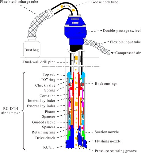
The formation of reverse circulation is based on Bernoulli’s principle or the Venturi effect. Exhaust gas discharged from the DTH air hammer flowed into the two types of nozzles. The exhaust gas that flows into the suction nozzles forms multiple high-speed jets. The air near the exits of the suction nozzles could be entrained into the jets by the jet-pump effect (Bartosiewicz et al., Citation2006), and a negative pressure zone is formed within the hollow-through channel of the drill bit. Subsequent to the impact on the bottom of the borehole, the vertical jets issuing from the flushing nozzles are refracted into the pressure-restoring groove (Bo et al., Citation2011), and the rock debris is swept into the central passage. The pressure differential between the negative pressure zone and the bottom of the borehole forms a lifting force which entrains the rock debris. Then, the mixed phase is returned to the ground surface through the central channel in the drilling system.
3. CFD simulations
3.1. Computational model and grid
Based on the optimized structural parameters reported in previous studies (Luo et al., Citation2016), six suction nozzles with a 30° elevation angle were distributed uniformly in a circle with one layer and two flushing nozzles were placed vertically and symmetrically in the bit body. All nozzles were 6 mm in diameter. The outside diameter of the bit body measured 89 mm, while the central channel was 33 mm in diameter. In addition, the bit face is situated 8 mm above the bottom of the hole with an annular gap of 3 mm between the drill bit and borehole.
The geometry model was established using the Solidworks software. Four sets of grids for computational domains were meshed to analyse the grid sensitivity, including three sets of polyhedral cells and one set of hexahedral cells. Table demonstrates a summary of the simulation results obtained with grids of different densities, and the maximum difference was less than 6%. Considering the finely balanced time cost and simulation accuracy, we adopted herein, computational domains meshed with uniformly structured hexahedral cells.
Table 1. Analysis of grid sensitivity and grid type.
3.2. Compressibility of gas
Air is generally considered incompressible below a Mach number (Ma) of 0.3, approximately corresponding to a flow speed of 100 m/s. The air flow speed in most regions of an RC-bit, for example, the annular space and central passage, is observed to be within the air-incompressible-flow regime (Larose & D’Auteuil, Citation2008); such that using incompressible air as the primary phase in the simulations is reasonable. Because some local air compressibility still exists in the vicinity of the suction nozzles, a series of single-phase simulations were conducted to verify the ability of incompressible air to obtain acceptable results for suction capacity. The model and grid used are the versions proposed in Section 3.1. The air inlet is defined as the mass flow inlet, the two outlets are defined as a pressure outlet with a value of 0 Pa gauge, and the rest of the flow domain boundaries are defined as no-slip stationary walls. The coupled algorithm solution was chosen to achieve pressure-velocity coupling, while the standard k-epsilon model was used to solve the turbulence kinetic energy () and its dissipation rate (
). In terms of materials, the incompressible air has a constant density of 1.225 kg/m³, while the density of the compressible air is in accordance with the ideal gas law, as shown in Eq. (1):
(1)
(1) where
is the operating pressure,
is the local static pressure relative to the operating pressure, R is the universal gas constant, T is the temperature, and Mw is the molecular weight.
Note that the energy conservation should be met in a compressible analysis; thus, energy terms are calculated, which requires more computational resources and significantly increases the convergence time.
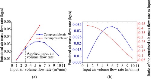
The variation in the entrained air flow rate with the increase in the input air volume flow rate is illustrated in Figure (a). From the simulations, it is clear that the use of incompressible air as a substitute for compressible air is acceptable in our modeling works when the input air volume flow rate does not exceed 3 m3/min. However, the most interesting phenomenon observed from the data curves is that the entrained air flow rate decreases with an increase in the compressible input air volume flow rate when it exceeds the limitation of 6 m3/min. As shown in Figure (b), the suction capacity of the RC-bit reached its peak at 0.034 kg/s, while the ratio of the entrained air mass flow to the input decreases constantly. We can easily conclude that there is a limitation on the adjustment range of the input air volume flow rate during the practical drilling process; that is, as the depth of drilling advances, the reverse circulation capacity may deteriorate because of the increased pressure drop enhancing the air compression.
Figure 3. (a) Influence of air compressibility on the suction capacity. (b) Influence of the input air volume flow rate using compressible air (ideal gas) on suction capacity.
3.3. Governing equations and boundary conditions
The modeling methods of CFD simulation can be determined according to the concentration of the dispersed phase in the flow domain (Wang et al., Citation2017). The concentration can be calculated using the equation proposed by Larsen et al. (Citation1997) which is simplified and presented as:
(2)
(2) where
is the volume proportion of cuttings and expressed in percent, the rate of penetration ROP should be converted into metres per second, and
is the injection velocity of cuttings. Here, the three variables in Eq. (2) are investigated for detailed flow behavior of cuttings, and their values are listed in Table . The flow domain is defined as the dense phase according to the calculated concentration of cuttings using Eq. (2). The Euler-Euler method is applied to study the transport behavior of the transport of cuttings as it has no limitations on particle numbers, whereas the Euler–Lagrange method is not suitable when the dispersed phase occupation exceeds 10% (Wang et al., Citation2017).
Table 2. Part of parameters used in the simulations.
The Euler-Euler method treats the solid phase as a fully interpenetrating continuum in the gas phase. For simplicity, the continuity and momentum equations are solved with the basic assumptions enumerated below:
The mass of each of the two phases remains constant;
The size and density of the cuttings are uniform with defined value;
Both the phases are assumed to be incompressible.
Therefore, the continuity equation of both phases ( = air or solid phase) can be summarized as follows:
(3)
(3) where
is the space occupied by phase
.
and
are abbreviations for the density and speed of phase
, respectively. The momentum balance for the gas phase,
yields:
(4)
(4) and for which the solid phase
is modeled with the kinetic theory of granular flow (KTGF) considering the kinetic energy loss in collisions of cuttings. The momentum equation of the solid phase is:
(5)
(5) where
is the shared pressure of all phases,
is the gravitational acceleration,
is the coefficient of momentum exchange to and from the two phases. The
is the solid pressure with respect to the particle temperature, as determined by Ding and Gidaspow (Citation1990).
(6)
(6)
and
are the phase stress–strain tensor of the gas and solid phases, respectively, and are given by (Ansys Fluent, Citation2019):
(7)
(7)
Here and
are the shear and bulk viscosity of phase
.
The standard k-epsilon model is considered here to describe the turbulence kinetic energy () and its dissipation rate (
). The standard wall function method was utilized to treat near-wall shear flow. The SIMPLE algorithm scheme is selected to achieve pressure-velocity coupling. The QUICK algorithm was selected to discretise the volume fraction, whereas the second-order upwind scheme was employed for all discrete equations.
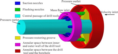
Figure shows the boundary conditions used in the two-phase flow simulations. The cell size should be larger than at least one particle diameter (Ansys Fluent, Citation2019). Alobaid (Citation2018) suggested that the preferred ratio between the grid size and particle diameter should be 2–3, Wang and Liu (Citation2020) also stated that the grid size should be 3–5 times large than the particle diameter. In this study, the thickness of the first layer of the grid was guaranteed to be three times the diameter of the particles. Additionally, considering the use of wall functions for near-wall treatment, boundary layers and refinement of the near-wall mesh were not used in this study. The cutting inlet was defined as the velocity inlet. The rest of the boundary conditions are kept the same as in the single-phase simulation in Section 3.2. Table formulates some of the parameters used, and the investigated range of parameters is listed in brackets.
Figure 4. Typical grid model and boundary conditions of computational domain.
4. Results and discussion
All simulations were considered to be in a steady state until the governing equations converged to the defined value. The dust suppression performance under the influence of each parameter was evaluated based on the suction capacity. The positions of the key sections are displayed in Figure .
Figure 5. Schematic diagram of the RC-bit flow field.
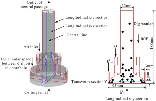
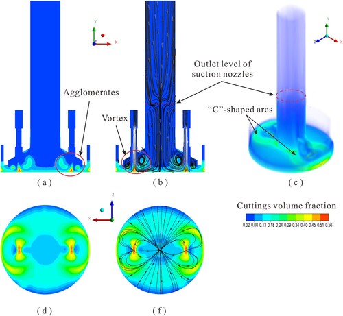
Figure presents an overview of the distribution of cuttings within the transport channel of a drill bit. As shown in the figure, the outlet level of the suction nozzles divides the debris distribution into dense and sparse phases. The cuttings deposit mainly in the central passage below the exit plane of the suction nozzle and the gap between the drill hole and the bit face. According to the contour plot, the most likely position for cuttings to escape from the annular gap is the outside of the X-Y section where the flushing nozzles are located. However, the cutting travel path exhibits an evident backflow and reflows into the central passage along the Z-axis direction, as shown in Figure (e). It is notable that there exist two horizontal c-shaped agglomerates of debris formed in the gap and three agglomerates in each pressure-restoring groove, which may be attributed to the vortexes that take shape in each pressure restoring groove. Cuttings are swept around under the impingement action of the high-speed airflow from the flushing nozzles. Some of the cuttings are trapped in the vortexes under the action of centripetal force and form a c-shaped agglomerate; the remaining cuttings are entrained into the central passage directly.
Figure 6. Typical distribution of cuttings: (a) volume fraction contour plot of X-Y section, (b) streamline distribution plot of X-Y section, (c) volume rendering of isometric view, (d) volume fraction contour plot of bottom borehole, and (e) streamline distribution plot of bottom borehole.
4.1. Effect of input air volume flow rate on suction capacity
It should be indicated that the input air volume flow is intermittent in practical applications because of the piston motion in the DTH air hammer, but it is still instructive to utilize continuous flow in the modeling work. In this section, the effect of the input air volume flow rate on the suction capacity is discussed at Cfc = 20%, ROP = 10 m/h, D = 3 mm, 0 rpm, and φ = 0.01. Based on the investigation of the air compressibility effect on the suction capacity discussed in Section 3.2, the input air volume flow was no more than 3 m3/min.
As depicted in Figure , the volume fraction of solids decreased significantly when the input air volume flow rate increased, especially in the annular gap below the drill bit face. This phenomenon may be owing to the expanded pressure differential between the low-pressure zone and the bottom of the borehole, as shown in Figure (b). Increasing the input volume flow rate enhances the flow rate of both suction and flushing nozzles and further increases the spray velocity of flows, which results in an improved entrainment effect of suction flows and increased pressure differential inside the drill bit. This action effect yields a higher drag force and leads to a better reverse circulation performance of an RC-bit.
Figure 7. Contour plots of cuttings volume fraction.
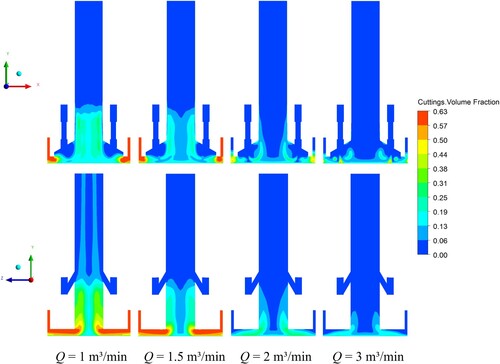
Figure 8. (a) Effect of the input air volume flow rate on the suction capacity. The negative values represent the air released to the atmosphere from the annular gap. (b) Static pressure distribution along the centerline.
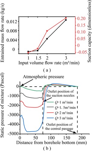
As shown in Figure (a), the suction performance of the RC-bit tends to increase with the increase in the input air volume flow rate. We observed that a little airflow escaped from the annular gap when the input air volume flow rate was less than 1.5 m3/min. This is because the minimum requirement of the air volume flow rate is not satisfied (Sharma & Chowdhry, Citation1986). Cuttings tend to deposit at the bottom of the borehole with low air supply, and the transport efficiency decreases until the requirement is met. This result is different from the single-phase simulation in which the suction phenomenon occurs when the input air volume flow rate is 1 m3/min (Luo et al., Citation2016), which demonstrates that the addition of the solid phase exhibits a non-negligible effect on the suction performance.
4.2. Effect of rotary speed on suction capacity
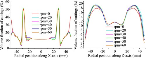
The RC-bits are kept revolving while drilling in the formations. To determine the effect of the rotary speed on the drill bit suction capacity, moving wall boundary conditions with different rotational speeds were utilized in the simulation models. The fixed parameters were set as Q = 3 m3/min, Cfc = 20%, ROP = 10 m/h, D = 3 mm, and φ = 0.01. As shown in Figure , the suction capacity of the rotary RC-bit is lower than that of the non-rotating bit. The variation trend of the suction capacity decreased first and then increased before decreasing again with increasing rotary speed. The reduced efficiency may be attributed to the complex flow field at the bottom of the borehole caused by the rotation, which causes the debris to collide with the wall, resulting in momentum loss. However, the maximum volume fraction of the aggregated cuttings was relatively lower in the rotating pattern; it had been reduced by 4%–5%, as shown in Figure . This trend is consistent with the findings of Zhang et al. (Citation2021) in the simulation of air-solid flow for pneumatic transport. The radial distribution of cuttings also varies depending on whether the drill bit rotates. As shown in Figure , the cutting volume fraction in the outer annulus decreased significantly along the X-axis. The change in the rotation speed of the drill bit was not effective in increasing the suction capacity. Because of the high airflow velocity in the pipe, the increase in rotation speed does not significantly contribute to the transport of cuttings (Ozbayoglu et al., Citation2012). However, the wider sweep of the flushing airflow in the rotating pattern helps to suppress the escape of cuttings from the annulus.
Figure 9. Effect of rotary speed on the suction capacity (Q = 3 m3/min).
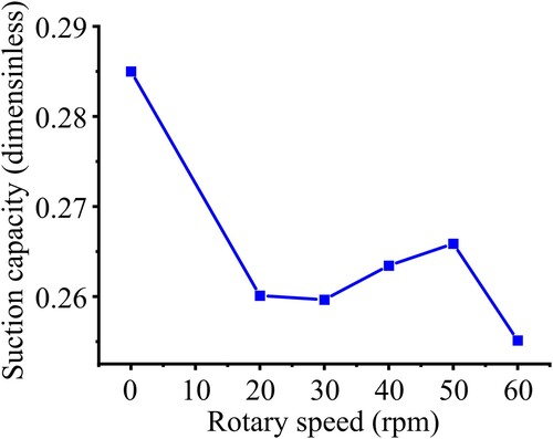
Figure 10. Volume fraction contour plots showing the distribution of cutting particles with different rotary speed (Y = 2 mm).
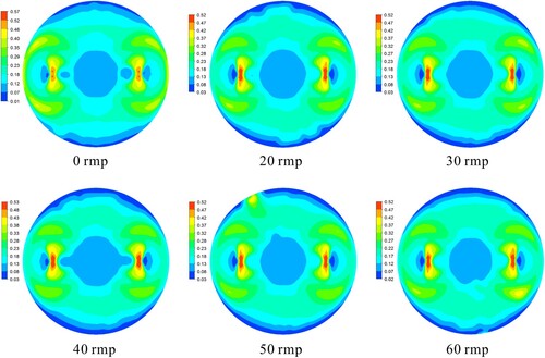
Figure 11. Volume fraction line plots showing the distribution of cutting particles in radial position with different rotary speed (Y = 2 mm).
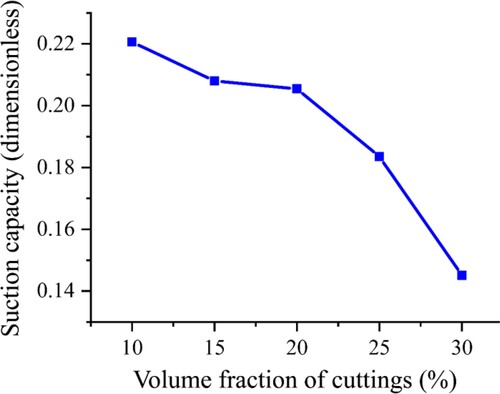
4.3. Effect of the feed concentration on transport of cuttings
According to Eq. (2), when the ROP is constant, a higher feed concentration of cuttings (Cfc) corresponds to a lower initial velocity of cuttings entering the central passage. In this section, Cfc of the gradient is varied in increments of 5%, and the other parameters are set as Q = 3 m3/min, ROP = 10 m/h, D = 3 mm, 0 rpm, and φ = 0.01. As demonstrated in Figure , the aggregating zones are near the outlet of the flushing nozzles at the X-Y section, forming a c-shaped stationary bed with a high solid-phase volume fraction. This c-shaped stationary bed has an inhibiting effect on the outwards spreading of the flushing jet. The vast quantities of cutting particles corresponding to higher feed concentrations cannot be transported fluently and are deposited in the annular gap owing to inefficient sweeping of flushing flows. This is the main reason for the decrease in suction capacity with the feed concentration, as depicted in Figure .
Figure 12. Volume fraction contour plots showing the distribution of cutting particles with different feed concentration: (a) Y = 2 mm, (b) Y = 4 mm, (c) Y = 6 mm, (d) X-Y section.
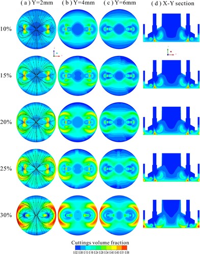
Figure 13. Effect of volume fraction of cuttings on the suction capacity.
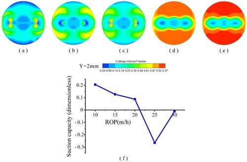
4.4. Effect of the ROP on the transport of cuttings
Rate of penetration (ROP) is an intuitive evaluation for drilling results (Hegde et al., Citation2019). Again referring to Eq. (2), in this section, we applied a constant feed concentration when investigating the effect of the ROP of drilling system on the transport of cuttings. This allows the ROP to be specified by different incident velocity.
Figure (a–e) demonstrate the distribution of the cutting volume fraction between the bit face and the borehole bottom at different ROPs. The fixed parameters were set as Q = 3 m3/min, Cfc = 20%, D = 3 mm, 0 rpm, and φ = 0.01. As the ROP increased, the volume fraction of the cuttings in the annular gap increased significantly. As shown in Figure (f), it is noteworthy that the suction capacity of the RC-bit did not decrease linearly with the ROP. The suction capacity first decreased and then increased back to near 0. Specifically, when the ROP is no more than 20 m/h, the suction capacity of the RC-bit drops linearly; however, it is capable of inhibiting the escape of air-carried cuttings from the annular space between the drill bit and the borehole wall. As the ROP continues to increase to 25 m/h, the suction capacity becomes negative which means that the air escapes from the annular gap outlet. The mass fraction of cuttings accounted for 80% of the escaped air-cutting mixture, and this value increased to 99% when the ROP reached 30 m/h. In other words, there is almost no exchange of air in the annular space at this ROP, as cuttings obstruct the air flow route.
Figure 14. Volume fraction contour plots showing the distribution of cutting particles with a distance of 2 mm from bottom. (a) ROP = 10 m/h, (b) ROP = 15 m/h, (c) ROP = 20 m/h, (d) ROP = 25 m/h, and (e) ROP = 30 m/h. Line plot (f) showing the impact of ROP on suction capacity.
4.5. Effect of particle diameter on the transport of cuttings
Numerical simulations were conducted in an RC-DTH air hammer drilling system with cutting diameters varying from 1 to 9 mm. Figure shows the change in Qent at different cutting diameters with fixed parameters at Q = 3 m3/min, Cfc = 20%, ROP = 10 m/h, 0 rpm, and φ = 0.01. Unexpectedly, the suction capacity did not vary monotonically with the increase in cutting diameter. We found that the performance of reverse circulation exhibits the best performance with a cutting diameter of 3 mm.
Figure 15. Effect of diameter of cuttings on the suction capacity.
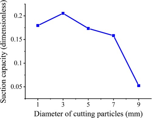
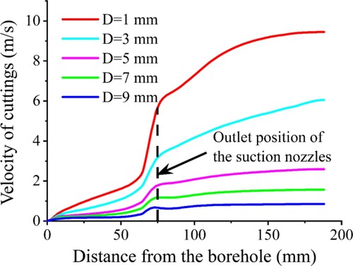
Figure provides an overview of the distribution of cutting velocity on the center line, as displayed in Figure . Cuttings are accelerated rapidly owing to the pressure differential before they pass through the outlet level of the suction nozzles, and then tend to level off. There are significant differences in the final stable velocity of cuttings with different cutting sizes. The increase in cutting size enhances the gravity effect, and thus reduces the final velocity. Considering that small cuttings with higher speed will hit the larger ones with lower speed, the cuttings may aggregate in the central passage and consequently affect the reverse circulation performance. Conceivably, the cutting size distribution could be a key factor influencing the suction capacity in the practical application of reverse circulation drilling.
Figure 16. Velocity of cuttings with different diameters on the central line of central passage.
4.6. Effect of the specularity coefficient on the transport of cuttings
The specularity coefficient , also known as the slip coefficient, is an empirical parameter determined by the roughness of the material surface. The Euler-Euler method is applied to describe the mutual effect between the solid phase and wall. In the air drilling system, the frequent collisions between cuttings and the drill tool surface are abrasive and cause inevitable wear. Therefore, we investigated the impact of drilling tool surface conditions characterized by the specularity coefficient on the flow behavior of cuttings.
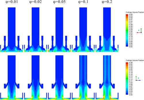
The values of the specularity coefficient are 0.01, 0.02, 0.05, 0.1, and 0.2. Figure illustrates the effect of the specularity coefficient on the suction capacity at Q = 3 m3/min, Cfc = 20%, ROP = 10 m/h, D = 3 mm, and 0 rpm. We can see that models with large specularity coefficients demonstrate a weakened capacity to entrain the air into the central passage, whereas the range of cuttings volume fraction has no evident difference in the annular gap, as displayed in Figure . We can observe that massive particles aggregate in the central passage between the bottom of the borehole and the outlet of the suction nozzles, and the occupation increases with the specularity coefficient. This is because the increased specularity coefficient indicates more energy loss from the action between the particles and the wall. Cuttings are trapped near the wall and impede the particle-laden flow. When the cuttings are transported through the outlet of the suction nozzles, because the jet flow forms a layer of ‘lubrication film’ between the cuttings and the wall, the transport of cuttings becomes smooth. However, the accumulation of debris in the lower position of the central passage still affects the annular space air flowing into the central passage, which may explain why the amount of sucked air decreases with the specularity coefficient.
Figure 17. Effect of specularity coefficient on the suction capacity.
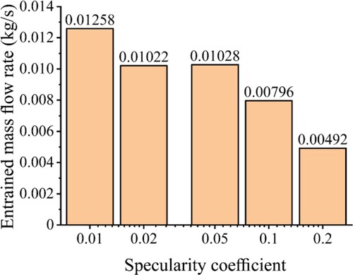
Figure 18. Volume fraction contour plots showing the distribution of cutting particles.
5. Conclusions
In this study, CFD simulations were utilized to investigate the suction capacity of an optimized reverse circulation bit by employing the Euler-Euler multiphase flow model. The effects of various parameters on the suction capacity are discussed systematically based on the simulation results. The following conclusions were drawn.
Cuttings exhibit non-uniform distribution features in the gas–solid flow field of an RC-bit. In the axial direction, cuttings mainly aggregate in the gap between the bit face and the borehole. They were swept and suctioned into the central passage by the airflow. In the radial direction, the cuttings tend to aggregate around the flushing position of the nozzles. Under the impingement action of the flushing jet, they would reflow or flow directly into the central passage along the Z-axis direction. In addition, dense walls and dilute cores were observed in the central passage.
In terms of the transport of cuttings, there are two states in which the dust control performance of an RC-bit reduces or even fails. One is the accumulation of cuttings in the gap between the bit face and the borehole, and the other is the inefficient transport of cuttings in the central passage. With a stable air supply, a high ROP or feed concentration of the solid phase would cause aggregation of cuttings under the bit face. Air in the annular space was impeded by entering the central passage. Large-size cuttings or high specularity coefficients can also affect the transport of cuttings in the central passage, which may cause some energy loss or hinder the conveying of small-sized cuttings. A low input air volume flow rate can result in both cutting aggregation and inefficient transportation. This was caused by a poor pressure differential. The rotation of the drill bit was not effective in increasing the suction capacity. However, the application of the rotary pattern reduces the concentration of cuttings under the drill bit face, which is beneficial for the enhancement of reverse circulation at the bottom of the hole.
The simulation results are indicative of practical drilling operations. The rotation speed of the drill rig should be kept below 50 rpm to improve the dispersity of cuttings at the borehole bottom and to minimize the reduction in suction capacity. To balance the dust control performance and production efficiency, the input air volume flow is at least 2 m3/min, and the ROP should be limited to less than 20 m/h unless the input air flow rate increases. Meanwhile, the properties of the real-time obtained debris should be monitored, and the supplied air flow rate should be adjusted according to the cutting size.
6. Future work recommendation
It should be noted that the numerical simulations were modeled under simplified conditions. Specifically, the input air flow rate was stable on the time scale, and the effect of cutting inserts on the transport of cuttings was not considered. Furthermore, the impact performance of the DTH air hammer is another important factor that affects drilling efficiency. Further research regarding the dust control capability of RC-bit can focus on multiphase flow simulation using a dynamic modeling approach, and incorporate the effect of DTH air hammer into numerical modeling to make the simulations closer to the real situation.
Disclosure statement
No potential conflict of interest was reported by the author(s).
Additional information
Funding
References
- Alobaid, F. (2018). Numerical simulation for next generation thermal power plants. Springer International Publishing AG.
- Andrew, B. C., John, A. O., Jeanne, A. Z., William, A. H., Ernest, S. M., Michael, S., Eugene, A., Chris, C. C., & Earle, H. A. (2005). Reducing enclosed cab drill operator's respirable dust exposure with effective filtration and pressurization techniques. Journal of Occupational and Environmental Hygiene, 2(1), 54–63. https://doi.org/10.1080/15459620590903444
- Ansys Fluent. (2019). 19.0 ANSYS Fluent theory guide 19.0. Ansys Inc.
- Bartosiewicz, Y., Aidoun, Z., & Mercadier, Y. (2006). Numerical assessment of ejector operation for refrigeration applications based on CFD. Applied Thermal Engineering, 26(5-6), 604–612. https://doi.org/10.1016/j.applthermaleng.2005.07.003
- Bo, K., Yin, K., & Peng, J. M. (2011). Reverse circulation DTH hammer drilling technique. Global Geology, 14(4), 259–264. https://doi.org/10.3969/j.issn.1673-9736.2011.04.08
- Cao, P. L., Chen, Y. W., Liu, M. M., Chen, B. Y., & Wang, J. S. (2016). Analytical and experimental study of a reverse circulation drill bit with an annular slit. Advances in Mechanical Engineering, 8(9), 1–10. https://doi.org/10.1177/1687814016669471
- Ding, J., & Gidaspow, D. (1990). A bubbling fluidization model using kinetic theory of granular flow. AIChE Journal, 36(4), 523–538. https://doi.org/10.1002/aic.690360404
- Epelle, E. I., & Gerogiorgis, D. I. (2017). A multiparametric CFD analysis of multiphase annular flows for oil and gas drilling applications. Computers & Chemical Engineering, 106, 645–661. https://doi.org/10.1016/j.compchemeng.2017.08.011
- Ghalandari, M., Koohshahi, E. M., Mohamadian, F., Shamshirband, S., & Chau, K. W. (2019). Numerical simulation of nanofluid flow inside a root canal. Engineering Applications of Computational Fluid Mechanics, 13(1), 254–264. https://doi.org/10.1080/19942060.2019.1578696
- Hegde, C., Millwater, H., Pyrcz, M., Daigle, H., & Gray, K. (2019). Rate of penetration (ROP) optimization in drilling with vibration control. Journal of Natural Gas Science and Engineering, 67, 71–81. https://doi.org/10.1016/j.jngse.2019.04.017
- Laín, S., & Martin, S. (2012). Numerical calculation of pneumatic conveying in horizontal channels and pipes: Detailed analysis of conveying behaviour. International Journal of Multiphase Flow, 39, 105–120. https://doi.org/10.1016/j.ijmultiphaseflow.2011.09.006
- Larose, G. L., & D’Auteuil, A. (2008, July 20–24). Effect of local air compressibility on the areodynamics of rectangular prisms at mach numbers below 0.3 [Paper presentation]. BBAA VI International Colloquium on: Bluff Bodies Aerodynamics & Applications, Milano, Italy.
- Larsen, T. I., Pilehvari, A. A., & Azar, J. J. (1997). Development of a new cuttings-transport model for high-angle wellbores including horizontal wells. SPE Drilling & Completion, 12(02), 129–135. https://doi.org/10.2118/25872-PA
- Lecreps, I., Orozovic, O., Erden, T., Jones, M. G., & Sommer, K. (2014). Physical mechanisms involved in slug transport and pipe blockage during horizontal pneumatic conveying. Powder Technology, 262, 82–95. https://doi.org/10.1016/j.powtec.2014.04.058
- Leung, C.C., Yu, I.T., & Chen, W. (2012). Silicosis. The Lancet. 379(9830), 2008-2018. https://doi.org/10.1016/S0140-6736(12)60235-9
- Listak, J. M., & Reed, W. R. (2007). Water separator shows potential for reducing respirable dust generated on small-diameter rotary blasthole drills. International Journal of Mining, Reclamation and Environment, 21(3), 160–172. https://doi.org/10.1080/17480930601176846
- Luo, Y. J., Peng, J. M., Li, L. J., He, J. F., Gan, X., Yin, K., & Zhao, Z. Q. (2016). Development of a specially designed drill bit for down-the-hole air hammer to reduce dust production in the drilling process. Journal of Cleaner Production, 112, 1040–1048. https://doi.org/10.1016/j.jclepro.2015.08.014
- Mando, M., & Yin, C. (2012). Euler-Lagrange simulation of gas-solid pipe flow with smooth and rough wall boundary conditions. Powder Technology, 225, 32–42. https://doi.org/10.1016/j.powtec.2012.03.029
- McGlinchey, D., Cowell, A., & Crowe, R. (2012). CFD investigation of dense phase pneumatic conveying at a pipeline enlargement. Particuology, 10(2), 176–183. https://doi.org/10.1016/j.partic.2011.11.004
- Mosavi, A., Shamshirband, S., Salwana, E., Chau, K.-w., & Tah, J. H. (2019). Prediction of multi-inputs bubble column reactor using a novel hybrid model of computational fluid dynamics and machine learning. Engineering Applications of Computational Fluid Mechanics, 13(1), 482–492. https://doi.org/10.1080/19942060.2019.1613448
- National Institute for Occupational Safety and Health (NIOSH). (1992). Preventing silicosis and deaths in rock drillers. https://www.cdc.gov/niosh/docs/92-107/
- Organiscak, J. A., & Page, S. J. (1999). Field assessment of control techniques and long-term dust variability for surface coal mine rock drills and bulldozers. International Journal of Surface Mining, Reclamation and Environment, 13(4), 165–172. https://doi.org/10.1080/09208119908944243
- Ozbayoglu, E. M., Osgouei, R. E., Ozbayoglu, M. A., & Yuksel, E. H. (2012). Hole-cleaning performance of gasified drilling fluids in horizontal well sections. SPE JOURNAL, 17((03|3)), 912–923. https://doi.org/10.2118/131378-PA
- Ozbayoglu, E. M., Saasen, A., Sorgun, M., & Svanes, K. (2013). Critical fluid velocities for removing cuttings bed inside horizontal and deviated wells. Petroleum Science and Technology, 28(6), 594–602. https://doi.org/10.1080/10916460903070181
- Page, S. J. (1991). Respirable dust control on overburden drills at surface mines. In Proceedings of the 1991 American Mining Congress Coal Convention, Surface Mining II Session, Pittsburgh, PA (pp. 523–539).
- Peirano, E., Delloume, V., Johnsson, F., Leckner, B., & Simonin, O. (2002). Numerical simulation of the fluid dynamics of a freely bubbling fluidized bed: Influence of the air supply system. Powder Technology, 122(1), 69–82. https://doi.org/10.1016/S0032-5910(01)00393-X
- Peng, J. M., Ge, D., Zhang, X. X., Wang, M, & Wu, D. Y. (2018). Fluidic DTH hammer with backward-impact-damping design for hard rock drilling. Journal of Petroleum Science and Engineering, 171, 1077–1083. https://doi.org/10.1016/j.petrol.2018.08.046
- Reed, W. R., Listak, J. M., Page, S. J., & Organiscak, J. A. (2008). Summary of NIOSH research completed on dust control methods for surface and underground drilling. In S. Kral & E. Wunder (Eds.), Proceedings, Society for Mining, Metallurgy and Exploration e SME annual meeting and exhibit 2008: ‘New horizons - New challenges’ (pp. 79–87). Society for Mining, Metallurgy, and Exploration, Inc. Press.
- SC, State Council of the People’s Republic of China. (2018, June 27). Three-year action plan for winning the blue sky defence battle. http://www.gov.cn/zhengce/content/2018-07/03/content_5303158.htm
- Sharma, M. P., & Chowdhry, D. V. (1986). A computational model for drilled cutting transport in air (or gas) drilling operations. Journal of Energy Resources Technology, 108(1), 8–14. https://doi.org/10.1115/1.3231247
- Tang, L. B., Zhang, S. H., Zhang, X. X., Ma, L. K., & Pu, B. (2021). A review of axial vibration tool development and application for friction-reduction in extended reach wells. Journal of Petroleum Science and Engineering, 199, 1–12. https://doi.org/10.1016/j.petrol.2021.108348
- van Wachem, B. G. M., Schouten, J. C., Krishna, R., & van den Bleek, C. M. (1998). Eulerian simulations of bubbling behaviour in gas-solid fluidised beds. Computers & Chemical Engineering, 22, S299–S306. https://doi.org/10.1016/S0098-1354(98)00068-4
- Wang, Y., Williams, K., Jones, M., & Chen, B. (2017). CFD simulation methodology for gas-solid flow in bypass pneumatic conveying - A review. Applied Thermal Engineering, 125, 185–208. https://doi.org/10.1016/j.applthermaleng.2017.05.063
- Wang, Z., & Liu, M. (2020). Semi-resolved CFD–DEM for thermal particulate flows with applications to fluidized beds. International Journal of Heat and Mass Transfer, 159, 120150. http://doi.org/10.1016/j.ijheatmasstransfer.2020.120150
- Wu, D. Y., Yin, K., Yin, Q. L., Zhang, X. X., Cheng, J. Q., Ge, D., & Zhang, P. F. (2017). Reverse circulation drilling method based on a supersonic nozzle for dust control. Applied Sciences, 7(5), 1–15. https://doi.org/10.3390/app7010005
- Yin, Q. L., Peng, J. M., Bo, K., He, J. F., Kui, Y. L., & Gan, X. (2015). Study on dust control performance of a hammer drill bit. International Journal of Mining, Reclamation and Environment, 27(6), 393–406. https://doi.org/10.1080/17480930.2013.787703
- Zhang, H. T., Zhang, O. Y., Li, B. T., Zhang, J., Xu, X. Y., & Wei, J. P. (2021). Effect of drill pipe rotation on gas-solid flow characteristics of negative pressure pneumatic conveying using CFD-DEM simulation. Powder Technology, 387, 48–60. https://doi.org/10.1016/j.powtec.2021.04.017
- Zhang, X. X., Luo, Y. J., Fan, L. M., Peng, J. M., & Yin, K. (2019). Investigation of RC-DTH air hammer performance using CFD approach with dynamic mesh method. Journal of Advanced Research, 18, 127–135. https://doi.org/10.1016/j.jare.2019.02.001
- Zhang, X. X., Luo, Y. J., Gan, X., & Yin, K. (2019). Design and numerical analysis of a large-diameter air reverse circulation drill bit for reverse circulation down-the-hole air hammer drilling. Energy Science & Engineering, 7, 921–929. https://doi.org/10.1002/ese3.321