
 ?Mathematical formulae have been encoded as MathML and are displayed in this HTML version using MathJax in order to improve their display. Uncheck the box to turn MathJax off. This feature requires Javascript. Click on a formula to zoom.
ABSTRACT
Værnes church is one of the oldest mediaeval stone churches with the original wooden roof in Norway. The roof is made of several crossed layers of wooden boards connected with a large number of wooden dowels and has stood for centuries, but there are visible deformations in the lower parts of the structure. In this work, finite element models of the roof are presented in an attempt to characterise the behaviour of the wooden connections in the diaphragm. Two main scenarios are discussed: a first scenario that takes into consideration only the frame with line loads, considering the wooden boards merely as loads and a second scenario where the wooden boards are considered collaborating planks that influence the behaviour of the structure. As result of the work, it is possible to state that the wooden planks provide a stiffening effect, distributing the load on the gable walls. .
Introduction
The rehabilitation of historic timber structures plays a key role in the preservation of the rich cultural heritage in Nordic countries. Historic timber roofs are complex structures that aim to fulfil static and architectural requirements. The structural behaviour of historic timber roofs is influenced by the material availability and construction techniques of the carpenters.
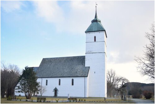
The conservation status and the mechanical characteristics (Bodig Citation1982) are the key elements for deciding the rehabilitative action. Both assessment and structural analysis of a building are crucial in order to understand the real behaviour of its structure. During the Middle Ages, timber roof trusses represented the most important construction technique of the time. Most of the buildings of this period hide timber trusses connected with carpentry joints with wooden pegs. In Norway, the surviving timber roofs of stone churches represent one of the three main groups of mediaeval wooden buildings in Norway, together with stave churches and timber houses. Among approximately 150 stone churches dating from the period from 1030 to 1537, only 17 original roofs have survived either partly or entirely (Storsletten Citation2002). The Trøndelag family of churches dates from this period, and in its pure form is represented by five structures with the original wooden roof. Værnes church () is one of the oldest mediaeval stone churches with an original wooden roof in Norway. Together with the assessment, a preliminary structural analysis was performed (Frontini et al. Citation2017).
Figure 1. Værnes church.
The choir of Værnes church has been dated from ca. 1141 through dendrochronological dating while the nave has been dated from ca. 1191 (Frontini et al. Citation2017). The timber roof structure of the nave is substantially preserved and the original roof structure is still standing after almost 900 years. The church was renovated in 1960. Small timber elements with a 50 × 50 mm section were added to the structure in order to connect the main and secondary rafters. In addition to this, a new stratigraphy of the roof was also installed. This renovation changed the way the loads are transferred to the supports.
The work presented in this paper aims to understand how the structure behaved before the renovation and if the roof, made of collaborating planks, affects its behaviour. The roof is built up from several crossed layers of wooden planks. The model studied in this work has been developed to investigate if the roof acts as a diaphragm and how it affects the redistribution of the loads and the stresses.
One of the first attempts to study a historic timber truss was made by Morris et al. (Morris et al. Citation1995), who demonstrated the capacity of FEA combined with historical research. It was very useful in order to clarify structural issues and reveal insights into the construction techniques. It helped also to identify the possible origins of historic structural types. This work showed the influence of connection modelling, concluding that the stiffness of the joints plays an important role in the computation of the global deformation and force distribution of historic timber trusses. In order to simplify the structural analysis, connections are usually designed by assuming an ideally pinned or rigid behaviour, neglecting the influence of the joint stiffness on the deflections. Scientific literature about timber connections has mostly focused on strength properties. The study of the stiffness and rotational stiffness properties of carpentry joints is more recent. The real behaviour of a timber connection is a semi-rigid behaviour that is somewhere between the two simplified models (Descamps et al. Citation2011). Usually, timber structures are modelled by means of a ‘beam’ and it is possible to identify two main approaches in the modelling of connections: ideal truss modelling and semi-rigid modelling. The first method, ideal truss modelling, assumes that all joints are hinges. The second method, semi-rigid modelling, has the aim of introducing a value for the rotational stiffness of the joints. This can be done in several ways: component methods, FEM or experimental tests. Drdácký et al. (Drdácký et al. Citation1999) in 1999 analysed how the behaviour of the timber structures can be theoretically described by a component method and the finite element approach.
One of the first attempts to model a semi-rigid joint was made by Bulleit et al. in 1999 (Bulleit et al. Citation1999). They showed the influence of the semi-rigidity of connections on the behaviour of timber structures. A well-defined load‒displacement behaviour of the joint can lead to a more efficient structure.
Chang et al. in 2006 (Chang et al. Citation2006), and Chang and Hsu in 2007 (Chang and Hsu Citation2007), analysed the rotational stiffness of a traditional Nuki joint using an experimental approach and the spring method.
They concluded that the rotational capacity and stiffness of the Nuki joint were sensitive to the gap size and their study found a maximum value of 0.065 MNm/rad. Descamps et al. in 2009 (Descamps and Guerlement Citation2009) studied and improved the component methods, also through the use of FEM. They analysed a pegged tenon and mortise joint in different configurations. The rotational stiffness of the analysed connection ranged from 6.8 Nm/mrad to 13.3 Nm/mrad. They concluded that the rotational stiffness of the joints is an important parameter that needs further and thorough study and it should always be implemented together with the axial stiffness.
As explained in (Maraghechi and Itani Citation1984; Olsson and Rosenqvist Citation1996; Kevarinmaki Citation2000), the springs should behave as mutually independent and connect the nodes. In addition, eccentricity may be taken into account by means of fictitious elements.
Most software allows the introduction of rotational springs. In this work, a parametric study on the influence of the rotational stiffness is done. The aim of this parametric study is to give an insight on the influence of the joints’ stiffness in Værnes church. This is done to establish the basis for a specific study on this topic.
The structure will be analysed taking into account a range of values of rotational stiffness of the joints.
A timber diaphragm is studied as a mechanism resistant to in-plane load. Most of the research has focused on wooden floors. Horizontal diaphragms, in historic timber structures, play a fundamental role in transferring the seismic actions. Very few experimental campaigns have been conducted on this topic (Corradi et al. Citation2006; Peralta et al. Citation2003) and all of them related to timber floors. In 1989, Falk et al. analysed a wooden diaphragm with the finite element method (Falk and Itani Citation1989). The wooden floors investigated are all connected with metal fasteners. The 3-dimensional effect of the diaphragm is influenced by the quality of the connections. Brignola et al. studied the in-plane stiffness of a wooden floor in order to create a framework for a performance-based assessment (Brignola et al. Citation2008). There were also studies related to a simplified spring-based model of the diaphragm (Giongo et al. Citation2014; Judd Citation2005; He et al. Citation2011). Few studies can be found about historic timber roof diaphragms. Cestari et al. modelled the wooden planks as a collaborating plate (Bertolini-Cestari et al. Citation2016). Wu et al. developed a model for prediction of lateral resistance and seismic response of the roof structure of a historic Chinese timber frame building (Wu et al. Citation2021). In the model, semi-rigid connections have been modelled and analysed to determine the rotational stiffness. Yaser in (Abdel-Aty and Amin Citation2018) studied the in plane stiffness of timber roofs and proposal for seismic retrofitting enhancing how the in-plane stiffness should be considered and not disregarded. Descamps et al. in (Costa et al. Citation2018) studied reinforcement in beams and joints in order to increase to increase the moment of resistance (and so limit the deflection too) or to increase the in-plane stiffness for lateral loads. Longarini et al. finally discussed proposal of roof-diaphragm solutions for masonry church (Longarini et al. Citation2019).
Description of the structure
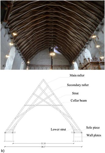
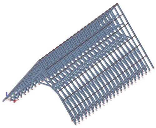
The church has a stone structure with a continuous foundation and a timber pitched roof constituted by 21 trusses. The structure is approximately 14.1 m wide; the angle of the roof is approximately 54°. The structure consists of the main and secondary rafters, wall plates embedded in the walls, collar beams and struts. The longitudinal system is composed of five parallel purlins that connect the main rafters and run along the whole longitudinal length. shows the roof in Værnes church.
Figure 2. Værnes church structure. (a) General view of the roof structure, (b) Truss elements.
In the structure, two main supports are identified: the lateral walls and the gable walls. The way the loads reach the supports depends on the relative stiffness of the timber elements, the connections between them and the connections between elements and supports.
It is possible to identify different structural levels in the church.
Regarding the timber members, during the assessment performed in Værnes church, visual grading was performed on eight trusses, three each at the ends and two in the middle of the church. No rotten elements were identified. The moisture content was analysed and the presence of knots and the direction of the fibres were also studied following standards (EN Citation338:Citation2016; EN Citation1912; EN Citation408). The structural elements were classified as strength class C24 (Frontini et al. Citation2017). In order to stay on the safe side, all the elements are considered in the C24 strength class, although some elements showed features to be classified in a higher class. In Værnes church, all the connections are made with single or double pegged half lap joints. In the first approximation, the connections are considered pure hinges, then a preliminary parametric study on rotational stiffness is performed. In the trusses, a hinged cross-link is added where the connections are located.
The connection between the frame and the wall is also very important. The wall provides the vertical support for both main and secondary rafters. The secondary rafters are connected to the sole piece with a step joint which can transfer horizontal loads. The sole piece and the inner wall plate are connected by a lap joint. The inner wall plate transfers lateral loads to the stone wall by compression. Thus, the secondary rafter transfers horizontal loads to the masonry wall .
Figure 3. Connection between the trusses and the lateral walls. (a) section drawing. (b), schematic representation of the model, from left to right: roller, roller and hinge. The Main rafter is not fastened to the outer wall plate and the sole plate can deform and slide along its axes. The secondary rafter is connected to the inner wall plate that is prevent from moving by the stone wall.
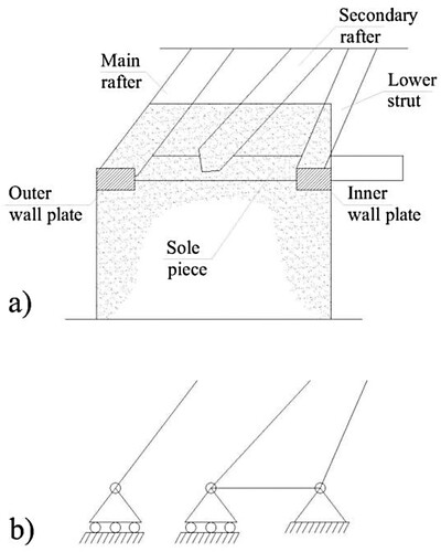
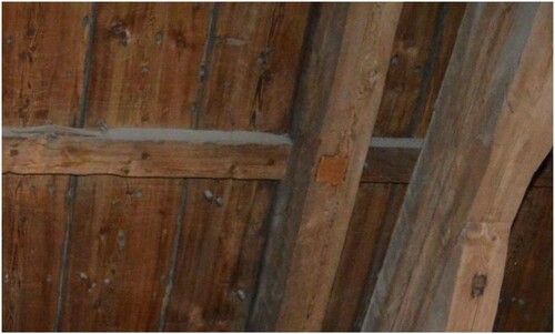
The main rafter is connected by a lap joint to the outer wall plate that can transfer horizontal loads to the stone walls just through friction. Thus, the main rafter and the outer wall plate can slide on top of the wall when the horizontal load exceeds the friction capacity. Furthermore, a small reinforcement work was done during the 1960s, connecting the main rafter and the secondary rafter with two wooden elements. The connection between the secondary rafter and the wall is modelled as a hinge, while the connection between the main rafter and the wall is modelled as a roller. However, the main focus of this work is related to the configuration of the church before the reinforcement. shows the reinforcing elements installed during the 1960s.
The purlins enter in the gable walls. Since the structure is cultural heritage, the assessment was subject to some restrictions. It was not possible to observe the real connection between the purlins and the gable walls. An experienced carpenter, Roald Renmælmo, stated that, from observing similar structures in central Norway, it is reasonable to assume that the purlins are connected to a loose rafter embedded in the stone gable walls as shown in . The rafter embedded in the gable wall is assumed to have the same cross-section as the main rafter and the connection between the rafter and the purlins is modelled as a hinge since the purlins are very slender and connected to the rafters with one wooden peg.
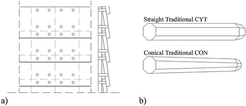
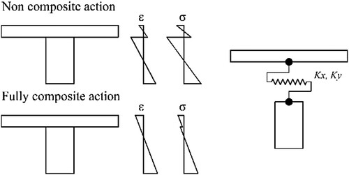
The connection between the purlins and the main rafter is represented as a hinge. The purlins are cut into the main rafter and connected with one dowel. The connection between planks and purlins and between planks and the main rafter is also an important factor. As can be seen in , the wooden boards are mostly connected with one wooden peg to each purlin. The connections between the main rafter and the wooden planks are also due to wooden pegs. There are several wooden pegs that run along the main rafter and connect it to the wooden planks in line. These dowels are usually conical and have a diameter of 20 mm. According to Roald Renmælmo, who worked on the restoration of the choir of the structure, the distance between the dowel is in the range of 20‒25 cm. Couples of pegs in the horizontal direction are not present so there is no bending resistance. Both purlins‒planks and rafter‒planks connections can be modelled as hinges. The rafter and the roof deck can develop a composite action, where the shear between the timber beam and the boards needs to be transferred through fasteners. There are two bounds of the composite actions: a fully composite action, where the two elements are rigidly connected, and a fully non-composite action with no transfer of horizontal forces between the two systems. The methodology adopted in this work is discussed further in section “Equivalent plate”.
The way the wooden boards are connected to each other determines the stiffness of the diaphragm. Nowadays, the roof is built up with several crossed layers of wooden boards connected with a large number of wooden dowels. The original and still existing configuration that is the focus of this work is composed of two layers. In this configuration, there were four dowels each overlapping the first layer with the second layer, two dowels without gaps and two with a gap. Data related to the wooden pegs’ shape, diameters and stiffness are discussed later in section “Second scenario”.
Figure 4. Reinforcement installed in the 1960s: two small wooden elements connecting the main and the secondary rafters.
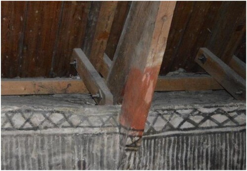
Figure 5. Purlins connected to a rafter embedded in the gable walls in Gildeskål church.
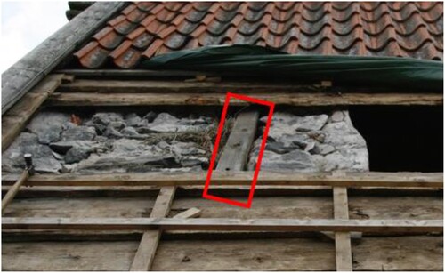
Figure 6. Connection between purlin and roof’s boards is visible.
It is possible to identify four main load cases related to different historical periods from archival research (Storsletten Citation2002; Stige et al. Citation2016; Gunnarsjaa Citation2006). summarises the dead loads of the different load cases.
Table 1. Evolution of dead loads during life of the structure.
Load case 4 refers to the current situation and is the main load case considered in this work. In load case 2, there is an asymmetric load, which requires special attention. In addition to these dead loads, snow load and wind load were considered. Snow and wind load were calculated according to the Norwegian annex of the Eurocodes.
Material and methods
In this work, two main scenarios are discussed.
First scenario
The first scenario takes into consideration only the frame with line loads, considering the wooden boards merely as loads without any collaborating effect in the structural behaviour .
Figure 7. Værnes church wooden roof.
In this scenario, the trusses are assumed to be the main resistant elements. The trusses transfer the loads to the lateral walls through the bottom supports and to the gable walls through the embedded rafter modelled at the ends of the structure.
shows the model of the first scenario.
Figure 8. Model representing scenario 1.
In the first scenario dead loads, snow loads and wind loads are considered in the calculation. The first three load cases are the main focus for scenario 1. Furthermore, a parametric study of the rotational stiffness is performed in order to understand the redistribution of bending moment in the case of modelling semi-rigid joints.
Five orders of magnitude of rotational stiffness, taken from the literature, are considered: 5, 10, 15, 50 and 65 Nm/mrad (Bulleit et al. Citation1999; Chang et al. Citation2006; Chang and Hsu Citation2007; Descamps and Guerlement Citation2009).
Second scenario
In the second scenario, the wooden boards are considered collaborating planks that influence the behaviour of the structure. The original and still existing part of the wooden roof is composed of two layers. During the assessment (Frontini et al. Citation2017), it was found that the peg diameters of the wooden diaphragm vary between 15 and 20 mm (). The main core of the roof is composed of two layers of wooden boards connected to each other with wooden fasteners. The second scenario is created by adding an equivalent plate, representing the wooden planks, to the first scenario.
Figure 9. (a) model representing the timber diaphragm typology. (b) wooden dowels shapes used.
First, an experimental campaign is performed in order to collect data about the wooden dowels and their stiffness (Frontini et al. Citation2018). Then, a solid finite element model of a portion of the roof is analysed in ABAQUS (Olsson and Rosenqvist Citation1996). This model is created to determine the mechanical properties of an equivalent plate to implement in the analysis of the global structure.
Then, the equivalent plate is modelled in SCIA (NEMETSCHEK GROUP Citation2016), a software specific for civil engineering (Kevarinmaki Citation2000). This equivalent plate is created so that it matches the mechanical properties of the roof model developed in ABAQUS.
Finally, the equivalent plate has been implemented to the beam model of Scenario 1.
Equivalent plate
The portion of the roof is modelled with boards 200 mm wide and 1000 mm long with a thickness of 20 mm.
The length of 1000 mm was chosen because this is the average distance between trusses.
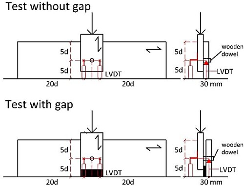
It was decided to use the number and locations of the dowels of the original configuration. Two main peg shapes are considered in this work: straight traditional and conical traditional (). For each shape, two diameters are considered: 15 and 20 mm. In total, four configurations are defined. In order to understand the real behaviour of the wooden conical pegs that connect the layers of the roof stratigraphy, an experimental campaign was carried out (Frontini et al. Citation2018). For this work, four main dowel typologies are considered. Two main shapes: straight and conical; and two main diameters: 15 and 20 mm. This leads to four main models (CON15, CON20, CYT15, CYT20). Monotonic quasi-static compression loading tests were performed as shown in . For more details, see (Frontini et al. Citation2018).
Figure 10. Single shear tests carried out (Frontini et al. Citation2018).
The results of the tests from (Frontini et al. Citation2018) and used in this work are shown in .
Table 2. Stiffness values of traditional wooden dowels.
The numerical models developed for the historic wooden roof are based on experimental results and they are used to simulate the structural response of the different timber diaphragm typologies.
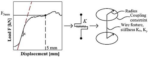
ABAQUS 14.1 software was used to develop the FE model. The pegs are modelled with a link that simulates an elastic behaviour in the x and y directions equivalent to the stiffness of the peg. This was done in order to simulate the translational stiffness of the connections. The typology of links used in ABAQUS is the ‘wire feature’, in this case used to idealise a solid in which both the thickness and depth are small compared to its length. This link provides a connection between two nodes, allowing independent behaviour in three directions. In the model, the link was associated with two stiffnesses, Kx and Ky, as shown in . The values implemented in Kx and Ky are taken from , the results of the experimental campaign. At both ends of the wire feature, a coupling constraint is added to simulate the influence of the radius of the wooden peg.
Figure 11. Links to simulate the stiffness of the wooden dowels.
The continuum plate element SC8R (three-dimensional stress/displacement element) was selected from the element library. This element is suitable for thin and thick plate applications and it is more accurate in contact modelling than conventional plates.
According to the density measurements (Frontini et al. Citation2018) and based on the Treteknisk report (Peralta et al. Citation2003) and Bodig (Falk and Itani Citation1989, it was decided to use the values in as the mechanical properties of the wood material. The wood species is modelled as orthotropic material.
Table 3. Mechanical properties used for the wood material.
These data, in addition to the results from the experimental campaign, were necessary to develop the solid model in ABAQUS (Dassault Systemès Citation2014).
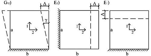
The solid model is then tested in order to extract the following mechanical properties: E1, E2, G12.
E1 is obtained by imposing a displacement Δ in the direction 1, E2 is obtained by imposing a displacement Δ in the direction 2 and G12 is determined by imposing a deflection Δ of 30 mm (to remain in the elastic phase) where the total dimensions a and b were 1000 mm ().
Figure 12. Procedures to determine E1, E2 and G12.
These properties were used in SCIA to assemble the stiffness matrix of the equivalent plate using the following formulas:
1)
(2)
(2)
(3)
(3)
(4)
(4)
(5)
(5)
(6)
(6) where h is the thickness. D11 and D22 are the flexural stiffness in the x and y directions. D12 is the mixed stiffness of D11 and D22 (transverse contraction). D33 is the torsional stiffness. D44 and D55 are the shear flexural stiffness in the x and y directions. G13 and G23 are used for the calculation of the stiffness D44 and D55. These are the stiffness for shear force deformation. In this model, D44 and D55 are assumed much larger than the other stiffnesses in order to neglect the shear force deformation. Since the plate is very thin (h<<L/5), the shear effect can be neglected and the software operates under the Kirchhoff–Love theory for plates.
For each shape and diameter of wooden dowels, an equivalent plate is created. In total, four models are created: 15 mm conical, 20 mm conical, 15 mm straight, and 20 mm straight.
The thickness is adjusted to match the bending behaviour.
One may argue that changing the thickness influences not only the bending but also the other properties. The model was accurate enough to allow a change in thickness of only 2 mm. The effect of this change is negligible for the other properties.
All four models were also tested in bending. The portion of the roof simulated was constrained by a symmetric boundary condition on the sides, where it is connected with the rafters. A vertical displacement was applied in the centre of the portion of the roof and the reaction forces were obtained.
Using plate elements in SCIA, the thickness of the plate was adjusted in order to match the forces and displacements from the ABAQUS simulation. The mechanical properties of the equivalent plates were defined with the abovementioned method. These plates were loaded in same way that the ABAQUS models were loaded. In this way, the equivalent thickness was calculated , .
Figure 13. Bending test of the roof portion in ABAQUS.
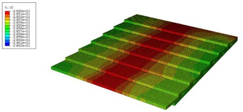
Figure 14. Bending test of the equivalent plate in SCIA.
Once all the mechanical properties of the equivalent plates are determined, the model of the global structure is created.
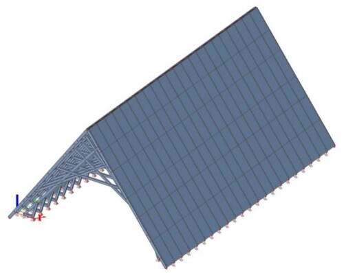
shows the model representing Scenario 2.
Figure 15. Model representing Scenario 2.
Also in the second scenario, dead loads, snow loads and wind loads are considered in the calculation. The load cases 1, 2 and 3 are the main focus of Scenario 2 but load case 4 is also studied.
Results and discussion
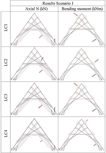
In Scenario 1, the loads are transferred directly to the bottom support in the lateral walls. The first three load cases are analysed. Regarding the load case 1, the axial forces and the bending moments are very low. In this situation, the structure is safe.
show the axial forces and the bending moment diagrams of Scenario 1 (load cases without wind action). In this analysis, the joints are still considered hinges.
Figure 16. Scenario 1, Results.
The structure is able to withstand this kind of load and even in the case of wind load the structure is far from failure.
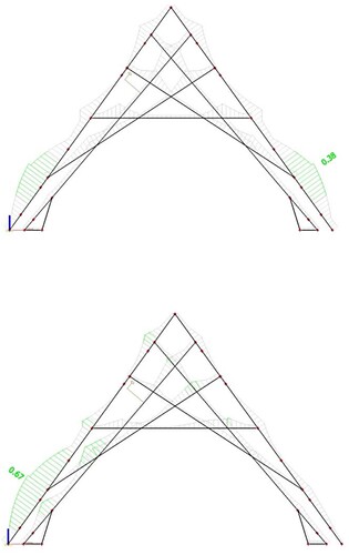
shows the ULS unity check for Scenario 1 – LC1, both with and without wind.
Figure 17. Scenario 1, LC1. Unity check. Above, without considering the wind load: 0.38. Below, considering wind load: 0.67.
Regarding the LC2, as expected, the axial forces and the bending moments are asymmetrical. The maximum value of bending moment reached with LC2 is 6.3 kNm, while the maximum axial force is 19.5 kN, on the side of the structure where the heaviest load is acting.
In LC2, considering the wind load, the bending moment reaches a value of 8.9 kNm. In this situation, the ULS unity check reaches the value of 1.01 in correspondence with the joint connecting the strut and the main rafter .
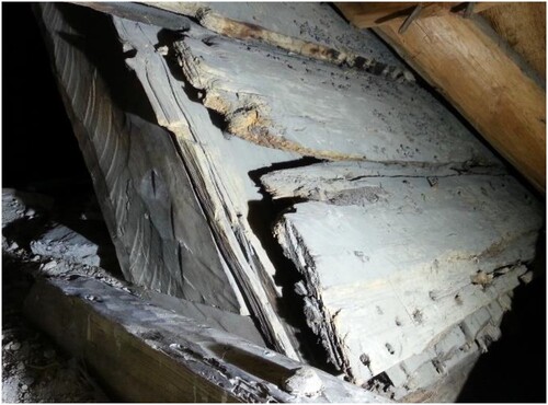
Figure 18. Damaged connection between main rafter and struts.
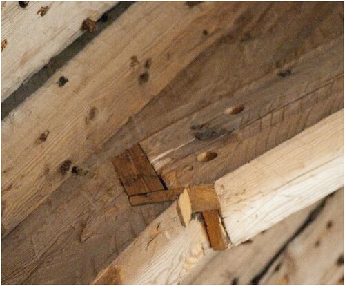
The struts work in tension, causing damage to the connection between them and the main rafter, as shown in (Frontini et al. Citation2017). The weakest part of the structure is then the connection between the main rafters and the struts. Due to the possibility of the outer wall plates moving laterally, the connection could have broken during this period. The current situation of the connection is shown in .
When considering the LC3, the symmetrical load stabilises the situation and the bending moment decreases to a maximum value of 5.9 kNm. In this configuration, the unity check shows that the structure is safe and not in danger, even considering the wind load.
Regarding the scenario 2 and the parametric study, since there are many combinations of results, in the following paragraphs, only the most valuable results are shown and discussed.
The parametric study of the rotational stiffness of the joints shows that, if the connections are modelled as semi-rigid, they reduce the value of the bending moment in the members.
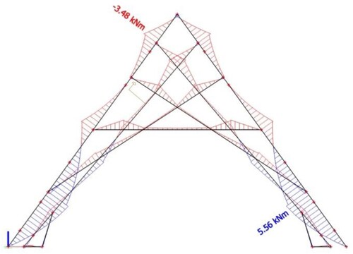
shows the bending moment diagram of the situation of LC3 considering a rotational stiffness equal to 65 Nm/mrad. The maximum value of the bending moment goes from 5.9 kNm to 5.56 kNm.
Figure 19. Scenario 1, LC3. Bending moments. Semi-rigid connections.
This might be a factor in why the connection between the strut and the main rafter did not fail completely, leading to a global structure failure. This reduction is beneficial for the structure as it is difficult to guarantee the strength of such old carpentry joints.
Obviously, this parametric study is just a preliminary study showing the effect of the semi-rigid joints in the Værnes structure. This topic needs further development. A thorough study is necessary to identify a real value of the rotational stiffness of the joints.
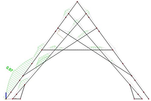
As shown in , the implementation of the rotational stiffness is useful in order to avoid a misleading interpretation of the results. Considering the rotational stiffness of the joints, it is possible to see that the ULS unity check is under 1. This means that, during the period when LC2 was acting, the connection was very stressed but did not fail and lead to the collapse of the structure. An appropriate study of the rotational stiffness of the joints is necessary in order to identify the magnitude of the influence of the joint’s stiffness in the structural behaviour.
Figure 20. Scenario 1, LC2. Semi-rigid joints. Unity check, considering the wind load: 0.97.
In Scenario 2, the way the wooden planks contribute to distribute the load is analysed. In this scenario, the possible composite action of the wooden planks with the main rafter is studied. As stated before, the wooden planks are connected to the main rafter with wooden dowels and the distance between them is about 20 cm. A parametric study considering the four different dowel typologies is developed. In this model, the main rafter is connected to the wooden planks with links. These links have two stiffnesses, Kx and Ky, derived from the results of the experimental campaign. In this case study model, the main rafters are 3 m long, simply supported, and they are loaded in order to get the same maximum value of bending obtained in Scenario 1. The results are then studied to get the effective width of the composite action .
Figure 21. Composite action of beam and wooden boards. Top left, non-composite action. Bottom left, fully composite action. Right, the model implemented for the study.
Only for the case of a conical dowel with 15 mm diameter was it possible to define an effective width less than 1 m (the distance between the two rafters).
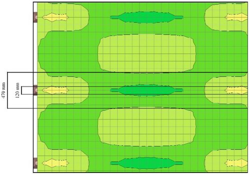
shows the extent of the effective width. The picture shows principal stress σ1. At a distance of 230 mm from the middle of the beam, it is possible to identify an inversion of stress, from −0.3 MPa to about + 0.3 MPa.
Figure 22. Effective width of the model with conical dowels, 15 mm diameter.
In the other three configurations, the wooden planks deform together with the main rafter and there is no inversion of stress.
After this analysis, it was decided to choose 470 mm as the effective width for the case study with conical dowels, 15 mm in diameter. For the other three configurations, the effective width is equal to the distance between two rafters.
Regarding Scenario 2, a comprehensive parametric study is performed: four typologies of equivalent shells, three main load cases and five values of rotational stiffness are considered.
With the contribution of the equivalent shell, the results show that the wooden roof redistributes the load into the gable walls. The wooden planks have a double effect: stiffening the roof and redistributing the load. shows the bending moment diagram of the LC3 with the shell CON15 and hinged joints.
Figure 23. Scenario 2, LC3, CON15, hinged joints. Bending moments.
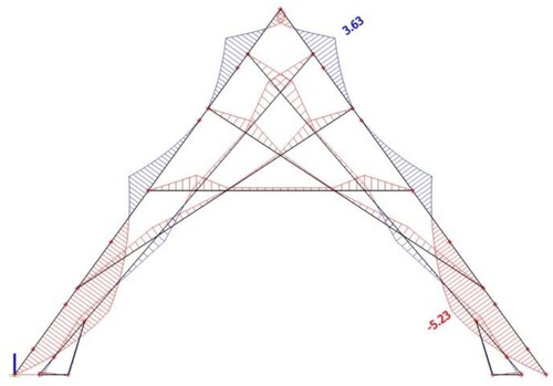
Regarding the LC2, the bending moment is higher, as seen in Scenario 1. The maximum load is equal to 5.65 kNm. The effect of the equivalent shell is more evident if the typology CYT20 (straight dowels, 20 mm diameter) is considered. The shell is stiffer and the bending moment decreases to 5.17 kNm.
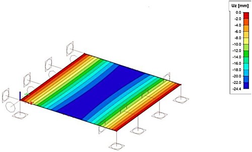
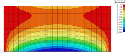
shows the displacements of the wooden planks in the roof. It is possible to see how the roof is deforming at the centre of the church while it is very stable in the vicinity of the gable walls.
Figure 24. Scenario 2, LC3, CYT20, hinged joints. Displacements of the shell element.
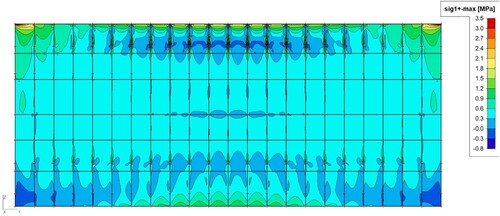
In it is possible to see the principal stresses σ1 in the plates. The equivalent plates redistribute the load to the gable walls. This effect is not observed when using only the frame model in Scenario 1.
Figure 25. Scenario 2, LC3, CYT20, hinged joints. Principal stress σ1.
Conclusions
In this work, several parameters are studied in order to understand the real behaviour of Værnes church: the effect of the wooden roof, the influence of the dowel typology in the wooden planks and the influence of the rotational stiffness of the carpentry joints.
A novel approach for modelling a historic timber roof is presented.
The approach is composed of the following steps:
Assessment of the structure
Experimental campaign on connections
Building an equivalent plate with FEM software
Analysing the global structure including the effect of the plates.
First of all, it can be stated that, before the reinforcement of the 1960s, the most dangerous load case was the second one, the asymmetric case. In this configuration, the connections between the struts and the main rafter almost reached failure. With only the frame model, one would conclude that the structure should have collapsed in that period. Considering the effect of the rotational stiffness and the collaborating plank, the ULS checks are passed.
From analysis of the two scenarios, it is clear that the model with the collaborating planks takes into consideration the stiffening effect of the roof. The plate elements representing the roof boards should be included to analyse the structure properly.
Regarding the specific case of Værnes church, it is possible to draw some conclusions regarding the wooden planks. The wooden planks provide a stiffening effect, distributing the load on the gable walls. Thanks to the plate elements, the bending moments and normal stresses are slightly smaller than the values related to the truss only model. At the same time, they respect the real trend showing the strut subjected to tension.
The preliminary parametric study related to the rotational stiffness of the carpentry joints shows the importance of modelling the connections as semi-rigid joints.
Further research should focus on the definition of models representing the carpentry joints in Værnes church.
Disclosure statement
No potential conflict of interest was reported by the author.
References
- Abdel-Aty, Amin YY. 2018. Proposals for seismic retrofitting of timber roofs to enhance their in-plane stiffness and diaphragm action at historical masonry buildings in Cairo. J Cultural Herit. 32:73–83.
- Bertolini-Cestari C, Invernizzi S, Marzi T, Spano A. 2016. Numerical survey, analysis and assessment of past interventions on historical timber structures: the roof of valentino castle. Wiadomości Konserwatorskie. 2:581–592.
- Bodig J. 1982. Mechanics of wood and wood composites.
- Brignola A, Podestà S, Pampanin S. 2008. “In-plane stiffness of wooden floor”.
- Bulleit WM, Sandberg LB, Drewek MW, O’Bryant TL. 1999. Behavior and modeling of wood-pegged timber frames. J Struct Eng. 125(1):3–9.
- Chang W-S, Hsu M-F. 2007. Rotational performance of traditional Nuki joints with gap II: the behavior of butted Nuki joint and its comparison with continuous Nuki joint. J Wood Sci. 53:401–407.
- Chang W-S, Hsu M-F, Komatsu K. 2006. Rotational performance of traditional Nuki joints with gap I: theory and verification. J Wood Sci. 52:58–62.
- Corradi M, Speranzini E, Borri A, Vignoli A. 2006. In-plane shear reinforcement of wood beam floors with FRP. Compos Part B: Eng. 37(4):310–319.
- Costa A, Arêde A, Varum H. 2018. [Building Pathology and Rehabilitation] Strengthening and Retrofitting of Existing Structures Volume 9 - Repair and Strengthening of Traditional Timber Roof and Floor Structures., doi:10.1007/978-981-10-5858-5 (Chapter 5).
- Dassault Systemès. 2014. “ABAQUS Version 6.14, user documentation,” Dassault Systemes, Providence, RI.
- Descamps T, Guerlement G. 2009. Component method for the assessment of the axial, shear and rotational stiffness of connections in old timber frames. 9ème congrès national de mécanique; Marrakech, Maroc.
- Descamps T, Van Parys L, Datoussaid S. 2011. Development of a specific finite element for timber joint modeling. Int J Comput Methods Eng Sci Mech. 12(1):1–13.
- Drdácký MF, Wald F, Mareš J. 1999. Modelling of real historic timber joints. Proceedings of the STREMAH 99 sixth international conference structural studies of historical buildings.
- EN 1912. Structural timber - Strength classes - Assignment of visual grades and species, CEN (European Committee for Standardization).
- EN 338:2016. Structural timber - Strength classes, CEN (European Committee for Standardization).
- EN 408. Timber structures - Structural timber and glued laminated timber - Determination of some physical and mechanical properties, CEN (European Committee for Standardization).
- Falk RH, Itani RY. 1989. Finite element modeling of wood diaphragms. J Struct Eng. 115(3):543–559.
- Frontini F, Siem J, Nilsen D. 2017. “Assessment of the structural perform-ance of a Norwegian historic timber structure: Værnes church.,” Structural health assessment of timber structures SHATIS 2017.
- Frontini F, Siem J, Renmælmo R. 2018. Load-carrying capacity and stiffness of wooden dowel connections. Int J Archit Herit. 14:376–397.
- Giongo I, Wilson A, Dizhur DY, Derakhshan H, Tomasi R, Griffith MC, Quenneville P, Ingham JM. 2014. Detailed seismic assessment and improvement procedure for vintage flexible timber diaphragms. Bulletin of the New Zealand Society for Earthquake Eng. 47(2):97–118.
- Gunnarsjaa A. 2006. Norges arkitekturhistorie.
- He M, Li S, Guo S, Ni C. 2011. The seismic performance in diaphragm plane of multi-storey timber and concrete hybrid structure. Procedia Eng. 14:1606–1612.
- Judd JP. 2005. “Analytical modeling of wood-frame shear walls and diaphragms”.
- Kevarinmaki A. Semi-rigid behaviour of nail plate joints, Ph.D. thesis, Helsinki University of Technology, 2000.
- Longarini N, Crespi P, Scamardo M. 2019. Numerical approaches for cross-laminated timber roof structure optimization in seismic retrofitting of a historical masonry church. Bull Earthquake Eng. 18:487–512.
- Maraghechi K, Itani RY. 1984. Influence of truss plate connectors on the analysis of light-frame structures. Wood Fibre Sci. 16(3):306–322.
- Morris ET, Black RG, Tobriner SO. 1995. Report on the application of finite element analysis to historic structures: westminster Hall, London. J Soc Architect Historians. 54:336–347.
- NEMETSCHEK GROUP. 2016. “SCIAEngineer16.1, Modelling in SCIA Engineer”.
- Olsson A, Rosenqvist F. 1996. Comparative computation of deflections in wooden roof trusses connected with nail plates (in Swedish), Lund University, Division of Structural Mechanics.
- Peralta DF, Bracci JM, Hueste MB. 2003. Seismic performance of rehabilitated wood diaphragms. Mid-America Earthquake Center CD Release. 03–01.
- Stige M, Pettersson KE, Hauglid K. 2016. Værnes kirke: en kulturskatt i stein og tre. Stjørdal historielag Instituttet for sammenlignende kulturfor-skning.
- Storsletten O. 2002. Takene taler: norske takstoler 1100-1350 klassifisering og opprinnelse. Arkitekthøgskolen i Oslo.
- Wu C, Xue J, Song D, Zhang Y. 2021. Seismic performance evaluation of a roof structure of a historic Chinese timber frame building. Int J Architect Herit. 16:1474–1495.