
 ?Mathematical formulae have been encoded as MathML and are displayed in this HTML version using MathJax in order to improve their display. Uncheck the box to turn MathJax off. This feature requires Javascript. Click on a formula to zoom.
ABSTRACT
The present article compares the effectiveness of two chemical compounds to reduce the growth of biofilm adhering to the tubes of a heat exchanger-condenser refrigerated by seawater. The compounds tested in the study were: a quaternary ammonium compound (QAC) and an aliphatic amine (triethanol amina, TA). Each biocide was applied intermittently in a first shock stage and in a second stabilising stage. Prior to biocide dosing, a biofilm was created in the inner surface of the heat exchanger tubes under study (AISI 316L and 316Ti stainless steel). The evolution of the biofilm during growing and treatment phases was followed by indirect measurements, i.e. fluid frictional resistance (f) and heat transfer resistance (Rf). The article also presents results of the impact of the different control strategies applied to the heat exchanger condenser efficiency. Both compounds removed the biofilm, and the tubes were practically restored to their clean condition. Ecotoxicology studies classified both biocides as environmentally harmless under the testing conditions.
1. Introduction
The growth of biofouling in industrial processes, in which seawater is involved, is an inherent part of their daily operation. Seawater is a readily available resource, with the main drawback that, under certain conditions, biological organisms present in the bulk seawater can lead to the formation of biological layers, known as biofilms, in different working areas of the asset. ‘Biofilm’ is a term that applies to a wide variety of manifestations of microbial aggregates. Biofilms are the oldest and most successful form of live on Earth, with fossil biofilms dating back 3.5 billion years and representing the first signs of life on Earth (Schopf et al. Citation1983). Aggregation and the association to surfaces offer substantial ecological advantages for microorganisms (Flemming Citation2008). Therefore, all surfaces in non-sterile wetted environments are colonised by biofilms, even at extreme pH values, high temperatures, high salt concentrations, radiation intensities and pressure (O’Toole et al. Citation2000; Flemming Citation2008).
Biofouling is observed in power generation facilities, paper mills, food production facilities, beverage industries, water desalination and drinking water treatment, storage and distribution systems, and on ship hulls. The consequences include losses of thermal performance of facilities, economic losses, inability to carry out proper maintenance practices, etc. Infrastructure in marine and offshore environments is particularly susceptible to biofilm growth, so biofouling could impact on the development and operation of new types of marine and offshore renewable energy exploitation along with existing maritime industries relating to transportation and oil-gas resources extraction.
In addition to biological fouling, or biofouling, other types of fouling include chemical reaction fouling, corrosion fouling, freezing fouling, particulate fouling, and precipitation fouling (Epstein Citation1981). In this paper the focus is primarily on biofouling by microorganisms (biofilm), termed microbial fouling, but fouling by macroorganisms such as mussels, oysters, barnacles, etc., termed macrofouling, is also discussed.
2. Biofouling processes
Biofouling is defined as the undesirable accumulation of a biotic deposit on a surface (Characklis Citation1990). According to Flemming (Citation2008), this definition is borrowed from heat exchanger technology and applies to both microbial fouling and macrofouling. In the marine environment, biofilms are formed by microorganisms, including bacteria, protozoa and microalgae, with the diversity and abundance of species present in the biofilm limited by factors such as competition for nutrients and toxin accumulation (Baena González Citation2005).
The biofouling process commences with the adsorption of small particles and organic molecules to a surface, followed by colonisation by microorganisms. That latter exudes a ‘slime’ of extracellular polymeric substances (xPS), which keep them together and glue them to the surface. The polymeric matrix is an exopolysaccharide complex of bacterial origin (Costerton et al. Citation1987); its composition is 95% water and is predominantly anionic, which enables the matrix to capture the minerals and nutrients from its surroundings. Subsequent colonisation of the surfaces by both microfouling and macrofouling species constitute the overall biofouling community (Polman et al. Citation2012). Cohesion forces within the biofilm are crucial for the adhesion structural and integrity of different strata of the biofilm (Morton Citation2000). The main cohesion forces are hydrogen bonds, the electrostatic interactions, and Van der Waals forces. Hydrogen bonds are formed by hydroxyls groups with cohesion energy ranging from 10 to 30 kJ Mol−1, and distance among them varying from 0.27–0.31 nm (Morton Citation2000). Electrostatic interactions are produced by electrically charged groups located in the xPS macro-molecules. Their cohesion energy varies from 12 to 29 kJ Mol−1, and distance among those groups is approximately 0.30 nm. Van der Waals interactions are mainly active between hydrophobic regions of the proteins and hydrophobic surfaces of the macro molecules. Their average cohesion energy is 2.25 kJ Mol−1, and the distance among them may vary from 0.3–0.4 nm (Morton Citation2000).
Research on the growth and development of microfouling has identified three main influential factors: those related with the substrata (composition, roughness, operational conditions and temperature), the physical–chemical and biological characteristics of the seawater (pH, seawater temperature, dissolved oxygen, organic carbon, inorganic components, biological activity and seawater flow), and environmental factors (weather and location) (Characklis Citation1990; Flemming Citation2008; Sheng et al. Citation2010; Bernstein et al. Citation2014).
Biofouling on surfaces that are in contact with seawater can reduce thermal performance of the asset, increase microbiologically influenced corrosion, increase drag, and increase the maintenance cost of equipment such as heat exchangers, pumps, and filters. Xu et al. (Citation2007) quantified the total annual fouling costs of a 350 MWe unit as 2.23 million dollars, an average of 6380.79 dollars per megawatt unit. With, in 2006, the total capacity of thermal power plants in China of 585,800 MW, the annual fouling cost for additional fuel and maintenance would be 3.74 billion dollars. With the additional cost of excess heat transfer surface area, the total costs would be 4.68 billion dollars (0.169% of GDP of China).
Regarding ship performance, the US Navy assessed the economic impact of hull fouling on a medium size combat ship, an Arleigh-Burke class destroyer (Schultz et al. Citation2011). Costs attributable to the fouling included extra fuel consumption and hull cleaning routines. Costs for hull cleaning and reapplication of coating were less than for extra fuel consumption, and the combined cost estimate was $56 million per year for all the destroyers in the Arleigh-Burke Class.
Biofouling of tubes within seawater heat exchangers is estimated to reduce cooling efficiency by 20–50% and to cost $15 billion dollars per year worldwide for the control of it (AMBIO Citation2007). Polman et al. (Citation2012) showed that biofouling has a significant effect on the operational capacity of a pumping station. In a submerged intake system, the head losses increased significantly, resulting in high additional operation costs estimated to be €970,000 per year in one case and €400,000 per year in another. The larger cost in the first case was due to higher design flow velocities and a much smaller pipe diameter.
3. Microfouling control in heat exchangers for marine engineering purposes
3.1. Traditional approaches
The mitigation of biofouling can employ physical (ultrasound, ultraviolet light, reverse flow, electromagnetic field), biological, and/or chemical (oxidants and non-oxidising biocides) methods (González et al. Citation2012). Biocides are compounds with one or more active components that destroy, deter, render harmless, prevent action or exercise control over any other harmful organisms by chemical or biological means (Royal Decree Citation1054/Citation2002). In industrial cooling systems, the compounds have a broad spectrum of activities as they have the capacity to limit the growth of a large variety of microorganisms (bacteria and algae) over a wide range of conditions. Due to their toxicity, they must comply with environmental regulations governing the discharge of effluent into the receiving environment (European Union Citation2006). This restriction can result in the allowable discharge concentration being below the effective level. Consequently, new, safer biocides are needed as alternatives to those currently in use.
Physical methods including ultraviolet light (López-Galindo et al. Citation2010a), electric fields (Abou-Ghazala and Schoenbach Citation2000), ultrasound (Bott Citation2001), heat and thermal treatments (Piola and Hopkins Citation2012; Rajagopal et al. Citation2012), biological methods (Dobretsov Citation2013) and chemical methods (Rajagopal et al. Citation2003) can be used as antifouling treatments. The choice of method depends on the nature of the biofouling microorganisms, on the hydraulic-thermal conditions of the process, on the costs of the treatment, on the safety requirements, and on the environmental impact. In some instances, the optimal cost/performance ratio has been reached by combining mechanical in-service cleaning and chemical short dosages (Cristiani Citation2005).
The focus of this study is on the use of chemical biocides for the mitigation of microfouling. According to the Health and Safety Executive (HSE Citation2015) that is the UK Competent Authority for biocides, a biocidal product is one which controls harmful or unwanted organisms through chemical or biological means. Biocides are used in a wide variety of industries to control organisms such as viruses, bacteria, fungi, insects and animals. More broadly, the EU Biocides Regulation (European Union Citation2012), which repeals and updates the Biocidal Products Directive 98/8/EEC, addresses chemical products that include disinfectants, pest control products and preservatives.
3.2. Novel approaches
3.2.1. Objectives of the study
The main objective of the study was to identify methods to eliminate the microfouling from the internal surface of the tubes of heat exchangers cooled by seawater. Two different novel and non-oxidizing biocides were dosed: a quaternary ammonium compound (QAC) and triethanol amine (TA). QAC is a fifth-generation compound obtained from N, N-dodecyldimethyl ammonium chloride (15%), alkyl dimethyl benzyl ammonium chloride (9.6%) and excipients (q.s. 100%) (CASRN 08-100-05129). QAC density is 965 kg/m3 (20°C), pH is 7,8 and its boiling temperature 100°C. TA is an aliphatic amine made of sodium hydroxide (7%), sodium molibdate (1–10%), sodium toliltriazol (1–20%), organic salts (1–10%) and excipients (q.s. 100%) (CASRN 34-0644). TA density is 1,060 kg/m3 (20°C), pH is 11 and its boiling temperature 100°C. The efficacy of these biocides was assessed under real working conditions in a pilot plant. The experiments were divided into two separate phases: a growth, and a treatment phase (González Citation2016).
The variables that indirectly define the growth of the biofilm inside the tubes are fluid frictional resistance and heat transfer resistance (Characklis et al. Citation1990). These variables indicate the presence of biofilm, but not information about the type of deposit. Fluid frictional resistance (f [dimensionless]) was calculated using Equation Equation1(1)
(1) (Characklis et al. Citation1990).
(1)
(1)
where d is the internal diameter of the tube (m), ΔP is the pressure drop between the tube inlet and outlet (Pa), L is the length of the tube (m), δ is the density of seawater (1,025 kg m−3) and V is the velocity of the coolant water (m s−1).
The heat transfer resistance (Rf [m2 K kW-1]) was calculated using Equation Equation2(2)
(2) (Characklis et al. Citation1990).
(2)
(2)
where At is the total surface covered by biofilm deposits in the tube (m2), Q is the rate of flow of the coolant water (m3s−1), δ is the density of seawater (1,025 kg m−3), cp is the specific heat at constant pressure (4.18 kJ kg−1 K−1), Tcond is the temperature in the shell (K), Tin is the temperature of the coolant water at the inlet (K) and Tout is the temperature of the coolant water at the outlet (K).
The total length of the experiments was 80 days and were conducted during spring and summer when biological activity is highest. During the growth phase (45 days), the biofilm was left to grow until the values of the indirect measurements, f and Rf, showed that its growth had stabilised. Once the growth phase was completed, the treatment phase was commenced with the biocides dosed in the assigned tubes. The treatment phase had two steps: a shock treatment phase (24 h on) with a maximum dose of 1.5 ppm of biocide over 5 days, which was aimed at eliminating the adhered biofilm; and a maintenance phase (6 h on, 6 h off) with a dose of 0.5 ppm of biocide over 30 days, aimed at maintaining the conditions that were achieved during the first phase of treatment. Efficacy was monitored by indirect measurements. Additionally, the efficiency of the heat exchangers was also measured by the parameter delta T (ΔT), which is the value to show the difference between two measured temperatures. It refers to thermal efficiency of the process and provides then a complementary measure to check the way the temperature of the liquid circulating through the tubes varies due to the internal adhesion of biofouling (González Citation2016).
To assess whether the biocides were environmentally friendly, the toxic impact of the residual biocide in effluents on fish life was studied. This was done using the acute toxic test standardised by the Oslo and Paris commissions (OSPAR Citation1995). Juvenile turbot (Scophthalmus maximus) were tested. The sample was exposed to an acclimation period of 12 days with the continuous renewal of seawater. The test conditions were as follows: a duration of 96 h, maximum load of 1.0 g fish per litre, tank volume 220 l, a photoperiod of 12–16 h per day, a temperature of 13.5–16.5°C, pH 8.2, a concentration of oxygen above 60% of the saturation value, replacing the trial medium after 48 h and without feeding. To determine the influence of the biocides physical–chemical characteristics of seawater, the pH, conductivity and amount of dissolved oxygen in the influent and effluent were measured daily. The criteria followed was death of the sample.
3.2.2. The pilot plant
The pilot plant was composed of two identical counter current heat exchangers built to standards of the TEMA (Tubular Exchanger Manufacturing Association). The exchangers consisted of a 240-mm (20-mm thick) outer casting and were built of AISI Type 304 stainless steel through which hot fresh water was circulated. Each unit had a tube bundle comprising four independent tubes that were set out lineally at 90° (3.163 mm long, 10.2 mm in interior diameter and 2.5 mm thick), through which seawater was circulated as the coolant fluid. Tubes were constructed of AISI 316L and 316Ti stainless steel (González Citation2016).
Seawater was pumped to the laboratory from the natural environment (Bay of Santander, Spain) then filtered and decanted into a 1 m3 tank. Details of the pilot plant are provided in Table . Differential pressure metres and resistance thermometers probe (Pt 100) were installed between the inlet and the outlet of the tubes to measure changes in pressure and temperature.
Table 1. Main technical data of the pilot plant.
The freshwater heater circuit was composed of two main boilers and one auxiliary boiler operated by an automated controller. Water from the heater of the thermal unit reached the panel exchanger via a primary circuit (80°C) and the heat transfer process was carried out using fresh water from the secondary circuit. In the secondary circuit, the water was driven at 1.8 bar and at a rate flow of 19 m3/h by a circulation pump. The temperature of freshwater at the inlet of the casing was set up to 36°C by means of a PID (Proportional–Integral–Derivative) automatic control loop.
Each tube had its own dosage circuit of a dosing pump with a pipe to the tube and a return pipe to the tank for the return of excess biocide, the dosage periods were controlled by a time switch. The data management system consisted of four multifunctional configurable modules to register and control all the parameters of the plant. The data were transmitted to a software programme (STEP® model DL01-CPU) via an RS232 communication port, where they were stored on a laptop. Data management tools enabled acquisition and storage of data from the pilot plant in real time (González Citation2016).
3.2.3. Results and discussion
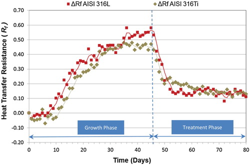
Figures and show the overall results for the QAC in both phases (growth and treatment) for the two indirect variables considered (f and Rf) in AISI 316L and AISI 316Ti tubes. As observed in other studies (Characklis et al. Citation1981; Characklis et al. Citation1990; Bott Citation1995; Jun and Puri Citation2005; Eguía et al. Citation2008; Trueba et al. Citation2013), the microbial growth phase in both experiments followed a sigmoidal curve, which reflects three distinct phases: (i) induction/colonisation or initial bacterial attachment, (ii) exponential growth or development of the biofouling film, and (iii) plateau or quasi-steady state in which the mortality balances growth of the biofilm. As it can be observed in Figures and (also in Figures and for TA), the initial values of both f and Rf dropped at the beginning of the experiments (colonisation phase). This phenomenon was previously reported by Cho and Choi (Citation1999), who concluded that it occurred due to the inherent roughness of the inside of the tubes, when the biofouling begins to accumulate on the rough surface. This initial negative tendency turns to positive values once rough cavities of the materials have been occupied by biofilm, decreasing the turbulences in the boundary layer and increasing the insulating effect of the biofilm (Characklis et al. Citation1990). The length of days for the growth of biofouling is shown in Table (for f) and (for Rf), where the final day of each aforementioned phase is indicated for both tubes. The value of f increased as the biofouling developed, presumably because the biofouling deposits increased the wall roughness, increasing the pressure drop in the tube. The biofilm growth curve was steeper and more mature in the AISI 316L material than the AISI 316Ti, due to differences in surface characteristics of the different materials used, possibly roughness, as rough surfaces will promote biofilm formation and maturation (Río Calonge Citation1999).
Figure 1. Evolution of the fluid frictional resistance (f) mean values during the study with QAC.
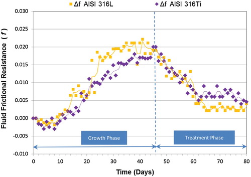
Figure 2. Evolution of the heat transfer resistance (Rf) mean values during the study with QAC.
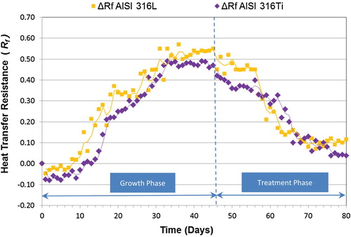
Figure 3. Evolution of the fluid frictional resistance (f) mean values during the study with TA.
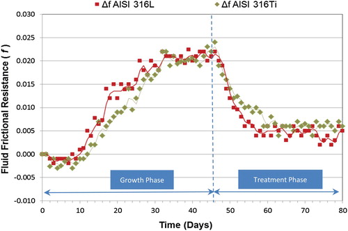
Figure 4. Evolution of the heat transfer resistance (Rf) mean values during the study with TA.
During the treatment phase, a shock dose of biocide was applied for 5 days in the materials under study. The treatment response time measured using f was 6 days for AISI 316L and 5 days for AISI 316Ti. During the maintenance phase (Figure ), lowest values for f were measured after about 18 days for AISI 316L and 16 days for AISI 316Ti. The f mean values for the major milestones during growth and treatment phases are shown in Tables and . Percentages of increase and decrease for frictional resistance are also given. In the case of AISI 316L material, the application of QAC enabled restoration of values to almost the initial conditions (Δf = 0.003). The Δf value for AISI 316Ti was 0.005, so the application of QAC was effective in both tubes.
Table 2. Fluid frictional resistance (f) mean values during the study with QAC – Growth Phase.
Table 3. Fluid frictional resistance (f) mean values during the study with QAC – Treatment Phase.
During the treatment phase (Figure ), the response time measured using Rf was 12 days for AISI 316L and 13 days for AISI 316Ti. At the end of the study, the values for ΔRf in both materials were close to those at the beginning of the experiment (Tables and ).
Table 4. The heat transfer resistance (Rf) mean values during the study with QAC – Growth Phase.
Table 5. The heat transfer resistance (Rf) mean values during the study with QAC – Treatment Phase.
As previously described the microbial growth phase also followed a sigmoidal curve when the TA biocide was studied, and the final day of its sub-phases is specified in the Table (for f) and 8 (for Rf). The results obtained for the indirect variable (f) when the TA was applied are shown in the Figure .
During the treatment phase, the response time for the TA in AISI 316L was 3 days, which demonstrates the high penetrating characteristic of the TA in the biofilm. For AISI 316Ti, the response time was 1 day (even faster than in the previous case). During the maintenance phase (Figure ), the minimum value for AISI 316L was reached at day 23; and the minimum value for AISI 316Ti was reached at day 21.
The f mean values for the major milestones during growth and treatment phases are shown in Tables and . After the application of TA, values close to the initial ones were achieved (AISI 316L, Δf = 0.004; AISI 316Ti, Δf = 0.005).
Table 6. Fluid frictional resistance (f) mean values during the study with TA – Growth Phase.
Table 7. Fluid frictional resistance (f) mean values during the study with TA – Treatment Phase.
Figure 4 shows changes in Rf when the biocide TA is applied. The treatment response time measured using Rf was 2 days for both materials. At the end of the study (day 80) the Rf values were like those at the beginning of the study (day 0) (Figure ). Tables and show the major milestones of Rfmean values during growth and treatment phases. After getting maximum values of around 0.5 for both materials at the end of the growth phase, the application of TA reduced the biofouling to values around 0.1 (AISI 316L, ΔRf = 0.11; AISI 316Ti, ΔRf = 0.13).
Table 8. The heat transfer resistance (Rf) mean values during the study with TA – Growth Phase.
Table 9. The heat transfer resistance (Rf) mean values during the study with TA – Treatment Phase.
The increase in Rf values during the biofilm growth phase indicates a decrease in the thermal efficiency of the process. The overall efficiency of the equipment (measured by ΔT) decreased due to the formation of a solid and permanent biofilm in the internal surface of the tubes. For AISI 316L the mean reduction in thermal efficiency was 36.5%, and for AISI 316Ti the reduction was 40.6% (Table ). These figures demonstrate the high impact that biofilm on the internal surface of a heat exchanger condenser has on its thermal efficiency. The application of biocide (QAC and TA) restored the thermal efficiency of the heat exchanger-condensers to mean values of 83.65% (AISI 316L tubes) and 79.2% (AISI 316Ti tubes) (Table ).
Table 10. Summary of thermal efficiency decrease – Growth Phase.
Table 11. Summary of thermal efficiency decrease – Treatment Phase.
However, practical use of these biocides needs to be environmentally friendly as well as efficacious. An ecotoxicological test with juvenile turbot for the application of each biocide was carried out according to OSPAR guidelines (Citation1995). The result of the test showed 5.9% of mortality for the QAC (Table ) and 0% of mortality for the TA (Table ), so in both cases the mortality rate was under the limit of 10% set by OSPAR (Citation1995) and no abnormal behaviour or appearance in the fishes was observed. Concerning the QAC, Bartolomé-Camacho and Sánchez-Fortín (Citation2007) studied its toxicity by analysing the mortality rate, motionless, growing inhibition and behavioural changes in several fish species. The research concluded that total ammonium in environments with a low pH is better tolerated by fish fauna than when pH increases, so when pH increases, the low alkaline environment of our study could explain the low toxicity rate of the QAC. Regarding aliphatic amines, different toxicological studies have been conducted with Mexel® 432. Arehmouch et al. (Citation2002) tested this biocide with cyprinus carpio and it was found toxic particularly during long exposure to the agent (7–9 days) López-Galindo et al. (Citation2010b) also tested different doses of Mexel® 432 (0,5, 1 and 2 mg/l) in juvenile solea senegalensis (demersal marine flatfish), and a toxic effect over the specie (brachial function impairment, etc.) was observed. In comparison with the absence of toxicity for TA under our experimental protocol, these results suggest that the chemical formulation of different aliphatic amines and the different doses tested explain why the mortality rate has varied among studies.
Table 12. Ecotoxicological test results for the study with QAC.
Table 13. Ecotoxicological test results for the study with TA.
Under the current testing conditions both biocides can therefore be considered environmentally safe for both fishes and environment. Although it represents a positive indicator of safety in the application of those biocides, further studies on other marine species should be carried out.
6. Conclusions
The impact of microfouling is causing losses linked to the OPEX of the heat exchanger-condensers and consequently increasing the fuel bill and emissions footprint. The mitigation of microfouling in heat exchangers used in marine applications will improve the efficiency of the whole propulsion package installed on board.
The chemical compounds tested in the present study have showed the adequate characteristics in the mitigation of microfouling considering both indirect measures (f and Rf); it has been corroborated by ΔT temperature measurement. Consequently, the application of those biocides has restored the thermal efficiency of the heat exchanger-condensers to acceptable values.
Finally, ecotoxicological test with juvenile turbot has indicated that the application of the tested biocides in the doses proposed showed no adverse effects, although further studies on other marine species should be conducted.
Acknowledgement
The author would like to express his gratitude to Dr Emilio Eguía, Dr Félix Otero and Dr Alfredo Trueba from the University of Cantabria (Spain)for the support received.
Disclosure statement
No potential conflict of interest was reported by the author.
References
- Abou-Ghazala A, Schoenbach KH. 2000. Biofouling prevention with pulsed electric fields. IEEE Trans Plasma Sci. 28:115–121. doi: 10.1109/27.842878
- AMBIO. 2007. Advanced nanostructured surfaces for the control of biofouling. UK: University of Birmingham.
- Arehmouch L, Chillebaert F, Chaillou C, Roubaud P. 2002. Lethal effects of Mexel 432, an antifouling agent, on embryolarval development of common carp (Cyprinus carpio L.). Ecotoxicol Environ Safe. 40:110–118.
- Baena González MI. 2005. A study of the bacterial activity in cupper stainless steel [dissertation]. Seville (Department de Microbiology): University of Seville. Spain.
- Bartolomé-Camacho MC, Sánchez-Fortín S. 2007. Valoración de la toxicidad aguda de biocidas utilizados en ambientes de la vida privada y la salud pública sobre Artemia franciscana. [Assessment of acute toxicity of biocides used in private and public health environments on Artemia franciscana]. Revista Latinoamericana de Recursos Naturales. 3(1):90–97. Spanish.
- Bernstein R, Freger V, Jin-Hyung L, Kim YG, Jintae L, Herzberg M. 2014. Should I stay or should I go?’, bacterial attachment vs biofilm formation on surface-modified membranes. Biofouling. 30(3):367–376. doi: 10.1080/08927014.2013.876011
- Bott TR. 1995. Fouling of heat exchangers, 3ª ed. Amsterdam: Elsevier.
- Bott TR. 2001. Potential physical methods for the control of biofouling in water systems. Chem Eng Res Des. 79:484–490. doi: 10.1205/026387601750282427
- Characklis WG. 1990. Biofilm processes. In: Characklis WG, Marshall KC, editors. Biofilms: Wiley Series in ecological and applied microbiology. New York: Wiley; p. 195–231.
- Characklis WG, Marshall KC, McFeters GA. 1990. The microbial cell. In: Characklis WG, Marshall KC, editors. Biofilms: Wiley series in ecological and applied microbiology. New York: Wiley; p. 131–159.
- Characklis WG, Nevimons MJ, Picologlou BF. 1981. Influence of fouling biofilms on heat transfer. J Heat Transfer Eng. 3(1):23–37. doi: 10.1080/01457638108939572
- Cho YI, Choi B-G. 1999. Validation of an electronic anti-fouling technology in a single-tube heat exchanger. Int J Heat Mass Tran. 42:1491–1499. doi: 10.1016/S0017-9310(98)00196-3
- Costerton JW, Cheng KJ, Geesay GG, Ladd TI, Nickel JC, Dasgupta M, Marrie TJ. 1987. Bacterial biofilms in nature and disease. Annu Rev Microbiol. 41:435–464. doi: 10.1146/annurev.mi.41.100187.002251
- Cristiani P. 2005. Solutions to fouling in power station condensers. Appl Therm Eng. 25:2630–2640. doi: 10.1016/j.applthermaleng.2004.11.029
- Dobretsov S. 2013. Marine biofilms. In: Durr S, Thomason JT, editors. Biofouling. UK: Wiley-Blackwell; p. 123–133.
- Eguía E, Trueba A, Río-Calonge B, Girón MA, Bielva C. 2008. Biofilm control in tubular heat exchangers refrigerated by seawater using flow inversion physical treatment. Int Biodeterior Biodegrad. 62:79–87. doi: 10.1016/j.ibiod.2007.12.004
- Epstein N. 1981. Fouling technical aspects. In: Somerscales EFC, Knudsen EJ, editors. Fouling of heat transfer equipment. Washington, DC: Hemisphere Publ. Corp; p. 31–53.
- European Union. 2006. Directive 2006/44/EC of the European Parliament and of the Council of 6 September 2006 on the quality of fresh waters needing protection or improvement in order to support fish life. Off J Eur Union. L. 264:20–31.
- European Union. 2012. Directive 2012/528/EC of the European Parliament and of the Council of 22 May 2012 concerning the making available on the market and use of biocidal products. Off J Eur Union. L. 26:1–123.
- Flemming HC. 2008. Biofilms. In: Encyclopedia of life sciences. Chichester: John Wiley. http://www.els.net/ [DOI: 10.1002/9780470015902.a0000342].
- González JA. 2016. Application of alternative and environmentally friendly chemical treatments for the mitigation and control of biofouling in heat exchanger processes. Implications over the efficiency of heat exchangers – condensers cooled by sea water [dissertation]. Santander (Department of Ship Construction and Navigation): University of Cantabria. Spain.
- González JA, Polman HJG, Venhuis LC, Bruijs MCM, Van Aerssen G. 2012. Biofouling issue, global implications and solutions linked to offshore business. DNV KEMA Energy & Sustainability, The Netherlands. Marine and Offshore Renewable Energy Conference. RINA. London. UK.
- HSE: Health and Safety Executive. 2015. http://www.hse.gov.uk/biocides/basics.htm /.
- Jun S, Puri VM. 2005. A 2D dynamic model for fouling performance on plate heat exchangers. J Food Eng. 75(3):364–374. doi: 10.1016/j.jfoodeng.2005.03.064
- López-Galindo C, Casanueva JF, Nebot E. 2010a. Efficacy of different antifouling treatments for seawater cooling systems. Biofouling. 26:923–930. doi: 10.1080/08927014.2010.531464
- López-Galindo C, Vargas-Chacoff L, Nebot E, Casanueva JF, Rubio D, Solé M, Mancera JM. 2010b. Sublethal effects of the organic antifoulant mexel(R)432 on osmoregulation and xenobiotic detoxification in the flatfish solea senegalensis. Chemosphere. 79(3):78–85. doi: 10.1016/j.chemosphere.2009.12.054
- Morton G. 2000. Problems of biofilm in industrial waters and processes. In: Walker J, Surman S, Jass J., editors. Industrial biofouling: Detection, prevention and control. Chichester: John Wiley & Sons Ltd; p. 79–101.
- OSPAR. 1995. PARCOM protocols on methods for the testing of chemicals used in the offshore oil industry. Part B: protocol for a fish acute toxicity test. Oslo and Paris commissions; p. 25–34.
- O’Toole G, Kaplan HB, Kolter R. 2000. Biofilm formation as microbial development. Ann Rev Microbiol. 54:49–79. doi: 10.1146/annurev.micro.54.1.49
- Piola RF, Hopkins GA. 2012. Thermal treatment as a method to control transfers of invasive biofouling species via vessel sea chests. Mar Pollut Bull. 64:1620–1630. doi: 10.1016/j.marpolbul.2012.05.028
- Polman H, Verhaart F, Bruijs M. 2012. Impact of biofouling in intake pipes on the hydraulics and efficiency of pumping capacity. Desalin Water Treat. 51(4–6):997–1003. doi: 10.1080/19443994.2012.707371
- Rajagopal S, Jenner HA, Venugopalan VP, Khalanski M, et al. 2012. Biofouling control: alternatives to chloride. In: Rajagopal S, editor. Operational and environmental consequences of large industrial cooling water systems. New York: Springer; p. 227–271.
- Rajagopal S, Van der Velde G, Van der Gaag M, Jenner HA. 2003. How effective is intermittent chlorination to control adult mussel fouling in cooling water systems? Water Res. 37:329–338. doi: 10.1016/S0043-1354(02)00270-1
- Río Calonge B. 1999. Mitigation of biofouling in heat exchangers–condensers minimising the environmental impact in seawater [dissertation]. Santander (Department of Ship Construction and Navigation): University of Cantabria. Spain.
- Royal Decree 1054/2002. 11 October, which regulates the evaluation process for registration, licensing and marketing of biocides. Government of Spain, Ministry of the Presidency (BOE no. 247 of 15/10/2002).
- Schopf JW, Hayes JM, Walter MR. 1983. Evolution on earth’s earliest ecosystems: recent progress and unsolved problems. In: Schopf JW, editor. Earth’s earliest biosphere. Princeton, NJ: Princeton University Press; p. 361–384.
- Schultz MP, Bendick JA, Holm ER, Hertel WM. 2011. Economic impact of biofouling on a naval surface ship. Biofouling. 27(1):87–98. doi: 10.1080/08927014.2010.542809
- Sheng GP, Yu HQ, Li XY. 2010. Extracellular polymeric substances (EPS) of microbial aggregates in biological wastewater treatment systems: a review. Biotechnol Adv. 28:882–894. doi: 10.1016/j.biotechadv.2010.08.001
- Trueba A, Otero FM, González JA, Vega LM, García S. 2013. Study of the activity of quaternary ammonium compounds in the mitigation of biofouling in heat exchangers–condensers cooled by seawater. Biofouling. 29(9):1139–1151. doi: 10.1080/08927014.2013.830108
- Xu ZM, Zhang ZB, Yang SR. 2007. Costs due to utility fouling in China. In: Müller-Steinhagen H, Reza Malayeri M, Paul Watkinson A, editors. Proceedings of the 7th international conference on heat exchanger fouling and cleaning: challenges and opportunities. Engineering Conferences International Symposium Series, Vol RP5; 2007 Jul 1–6. Tomar, Portugal. p. 113.