
 ?Mathematical formulae have been encoded as MathML and are displayed in this HTML version using MathJax in order to improve their display. Uncheck the box to turn MathJax off. This feature requires Javascript. Click on a formula to zoom.
Abstract
Ballast water management and treatment is an on-going issue for marine industry including small and bulk carriers, cruise ships, passenger ships and cargo vessels. Several regulations are implemented at regional, national and international levels to minimise the environmental impacts related to improper disposal of contaminated ballast water at ports. In this study, an environmentally benign approach for managing the ballast water on marine vessels is proposed. Thermoelectric energy harvested from main engine’s waste heat is considered as a primary source of energy for a reverse osmosis desalination process, which recovers the ballast water in the form of clean water to provide for fresh water supplies in ships. A case study is presented to elaborate the proposed scheme. The effects of seawater temperatures and energy recovery schemes on the freshwater production rates are also discussed. The proposed scheme provides a promising approach to ballast water management while allowing to provide in situ treatment for its beneficial use in shipping operations.
Introduction
Ballast water management and treatment is an important part of the economic portfolio for marine industry operations (Balaji and Yaakob Citation2012). Increasing environmental awareness and stringent environmental regulations call for proper treatment and disposal of ballast water. Among the many environmental concerns associated with marine industry operations, environmental emissions and pollution footprint from fossil fuel consumption is a very critical concern. About 50% of fuel input supplied to marine engines results in waste heat through various forms such as main engine exhaust, scavenger air cooling, and other water cooling streams (Biswas et al. Citation2018). To improve energy efficiency, various approaches including waste heat recovery systems have been considered (Kristiansen et al. Citation2012; Suárez de la Fuente and Greig Citation2015; El Geneidy et al. Citation2018). Energy recovery systems to extract energy from waste heat sources include energy storage units, thermoelectric generation units, energy recycling through various recovery streams.
On the other hand, providing freshwater supplies for on board uses is a challenge (Pavić et al. Citation2017). The required quantities of freshwater would need storage and transportation. While on-board treatment of seawater is an option, desalination of saline water is an energy-intensive process (Gude et al. Citation2010a; Gude Citation2019). For this reason, the use of waste heat and renewable energy sources has been widely recommended and demonstrated in many regions of the world (Gude and Nirmalakhandan Citation2008a, Citation2008b; Gude et al. Citation2010b, Citation2011a, Citation2011b). The waste heat sources include reject heat from process industries, domestic air-conditioning units while renewable energy sources include solar, wind, geothermal, and wave energy technologies (Tay et al. Citation1996; Kumar et al. Citation2005; Wang and Ng Citation2005; Gude et al. Citation2010b; Gude Citation2015, Citation2016; Gude and Fthenakis Citation2020). In this study, a novel integrated thermoelectric generator (TEG) and membrane desalination (reverse osmosis, RO) unit is proposed. Electricity generated from TEG will be used for desalination of seawater in a RO unit. Because the seawater temperatures vary with seasons, the effect of source water is considered. Further, the effect of heating the feed water to 50°C with waste heat generated in the ship is evaluated . Specific energy consumption as well as the output rates of the membrane desalination unit are also discussed.
Methodology
While ballast water presents environmental concerns, it can also be considered a valuable resource from which freshwater can be produced through desalination processes. Large quantities of energy are required for freshwater production through desalination processes. These energy requirements can be provided by on-board waste heat sources as discussed before (Gude Citation2019). Therefore, specific objectives of this research are to: (1) evaluate the electrical energy recovery from the waste heat generated by a bulk carrier ship; (2) evaluate the specific energy consumption of a RO unit; and (3) quantify the freshwater output rates from the RO unit considering variations in the feed water temperature.
A case study is presented to elaborate the proposed scheme. An integrated TEG and RO unit driven by the electricity produced from the waste heat is considered. in this section, First, the waste heat recovery potential using thermoelectric generator is presented. Next, the specific energy consumption with and without energy recovery devices (ERD) and its variations with different feed water temperatures are presented.
Thermoelectric energy generation from waste heat
Thermoelectric generation (TEG) works on the principle of ‘Seebeck Effect’ which was introduced by T.J. Seebeck 1821. It was shown that a voltage differential can be generated between two dissimilar conductors and semiconductors in contact with each other when a temperature differential is applied (Figure A) (Singh and Pedersen Citation2016; Selvan et al. Citation2019). TEG modules produce electrical energy from thermal energy. A TEG consists of n-type (a material with excess electrons) and p-type (a material deficit in electrons) elements connected electrically in series and thermally in parallel (Singh and Pedersen Citation2016).
Figure 1. (A) Principle of thermoelectric generation from waste heat source; (B) the effects of ZT values and temperature differentials on the electrical conversion efficiency of a TEG; (C) Typical energy efficiency profile and losses in ship operations; and (D) Energy efficiency profile with waste heat recovery through thermoelectric generation.
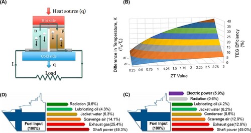
Heat from the hot region (source) is supplied to the hot junction of the module at a higher temperature and rejected via a cold junction to a lower temperature region (sink). A temperature gradient (ΔT) across the thermoelectric material drives electron charge carriers from the hot to the cold junction side and produces a voltage (ΔV). The magnitude of the thermoelectric voltage and the power produced depends on the temperature difference between the hot and cold junctions, the properties of the semi-conductor materials and the external load resistance (or electric current) (Selvan et al. Citation2019). Each thermocouple acts like a battery cell and can be arranged in series or parallel to generate the desired amount of voltage or current depending upon the generation requirements. A simple TEG module is shown in (Figure A). The performance of TEG device depends on the thermoelectric figure-of-merit (ZT) of the thermocouple material, which depends on the Seebeck coefficient, electrical conductivity, thermal conductivity and absolute temperature (Zhang and Zhao Citation2015). Materials with a high thermoelectric figure-of-merit generate higher electrical energy. Recent developments in thermoelectric materials have achieved higher ZT values over an increased temperature range (Petsagkourakis et al. Citation2018). Figure (B) shows the effects of temperature differential between the hot and cold regions and ZT values on TEG module efficiency. It is evident that the conversion efficiency can be significantly improved by increasing the ZT values (material dependent) and temperature differentials (source and sink dependent).
As mentioned earlier, the efficiency of main engines in marine vessels is around 50% despite numerous efforts to increase the fuel efficiency in the industry (Nguyen Citation2017). The remaining energy associated with the fuel is lost in different forms as shown in Figure (C). These include exhaust gases, cooling streams and radiation. Inclusion of waste heat recovery systems will provide opportunities for energy recovery while enhancing process efficiency, and reducing fuel consumption, thus minimising environmental emissions (Kristiansen et al. Citation2012). For example, by including a TEG unit, about 6% of total energy can be recovered (Figure D). It increases the overall fuel energy efficiency of the system to 55% (Kristiansen and Nielsen Citation2010).
Case study of thermoelectric waste heat recovery for desalination
A bulk carrier ship (M/V Rosita) with 52,000 deadweight tonnage (DWT) was studied to determine the waste heat recovery potential. This ship has a main engine of 7.8 MW and three sets of 480-kW auxiliary engines for electricity production with normal running condition of 85% load on the main engine. More details of the engine specifications can be found in Kristiansen and Nielsen (Citation2010). The recoverable heat from the flue gases is calculated by using the high (Th) and low (Tc) side temperature limits of 160°C and 29°C, respectively. The high side limit considers the corrosion issues while the low side limit is based on tropical seawater temperatures. The efficiency of a TEG is dependent on the temperature difference between Th and Tc and on the figure of merit Z. A constant value of Z = 0.002 was used to determine the efficiency (η) at maximum power output in the Equation (1) below (Champier Citation2017):
(1)
(1)
Table shows the different energy flows through various forms in M/V Rosita ship. The flue gas and stream flow are presented with representative temperatures. The estimated electrical energy recovery potentials are also shown in the table.
Table 1. Waste heat sources on the M/V Rosita.
Membrane desalination of ballast water via reverse osmosis
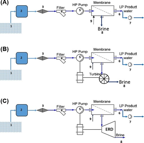
A reverse osmosis desalination process with a water recovery efficiency of 45% was considered. Different stages of treatment and energy requirements in the reverse osmosis process are shown in Figure . The major components of RO process involving energy consumption are: (1) feed water intake; (2) pretreatment; (3) high pressure pumps (with and without energy recovery); (4) membrane type and module; (5) post treatment; and (6) product supply (Gude Citation2011). Pretreatment systems consist of conventional as well membrane systems. Membrane pretreatment by microfiltration or ultra-filtration systems provides high quality feed to the RO membrane module. Pretreatment systems also include chemical dosing, mixing and filtration. The feed to the RO membrane after pretreatment is pumped through a high pressure pump and permeate is released at atmospheric pressure. The brine is returned to the source or run through an ERD to recover the hydraulic energy associated with it. Permeate produced from the module is post-treated to ensure the water quality meets the supply lines before it is pumped through the distribution system.
Figure 2. Process schematic of a reverse osmosis (RO) desalination unit with or without energy recovery device: (a) without energy recovery device; with energy recovery devices (b) Pelton turbine; and (c) pressure or work exchanger units (refer to Table for process locations and flow/pressure/energy values).
The energy requirements for the entire RO process can be expressed as follows (Gude Citation2011):
(2)
(2) where ET is the total energy requirement, Ein is the energy required to draw the feed water from the source, Ept is the energy required for pre-treatment and post treatment (micro filtration and pumping), Ehp is the energy required by high pressure pump, EA is the energy required by other accessories (chemical dosing, filter backwashing/cleaning and pumping the product water) and EERD is the energy recovered by the ERD. The energy requirements for individual components of the RO process are shown by numerical values in Table .
Table 2 Specific energy consumption calculations without an energy recovery device.
A production rate of 1 m3/h with a typical water recovery of 40% was assumed. Table shows the energy requirements for the pre-treatment, chemical dosing, high pressure pump, post treatment and membrane cleaning without an energy recovery device. The specific energy consumption for freshwater production using a Pelton-turbine type energy recovery device is shown in Table . Similarly, specific energy consumption for freshwater production using a pressure exchanger type energy recovery device is shown in Table .
Table 3. Specific energy consumption calculations with a Pelton turbine energy recovery device.
Table 4. Specific energy consumption calculations with a pressure or work exchanger unit.
Water recovery in a RO process can be improved by increasing the feed water temperature. The relation between permeate flux rate and the feed water temperature is shown in Equation (3) (Cardona et al. Citation2005; Gude Citation2011). Feed water temperature can be increased by utilising process waste heat. When process waste heat is not available, utilising solar collectors is a feasible option.
(3)
(3)
Results and discussion
About 133 kW of electricity can be generated by using the heat differences between the ambient seawater and different waste streams, i.e. flue gases, boiling water and cooling water as shown in Table . As shown in Figure (A), the permeate flux in the membrane module can be increased by increasing the feedwater temperature. An increase in the permeate flux up to 100% can be achieved if the feed temperature can be doubled, i.e. increased from 25 to 50°C. However, the temperature tolerance of the RO membranes is in the range 20–45°C. The permeate flux rate increases by 34% when the feed temperature is increased from 25°C to 35°C theoretically.
Figure 3. A generic relationship between the feed water temperature and the permeate flow (A); the effect of feed water temperature on permeate flow rate (B); the effect of feed water temperature on specific energy consumption (C); and the specific energy consumption including thermal energy requirements.
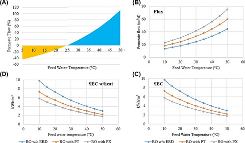
Figure (B) shows the effect of feed water temperature on permeate flux (m3/d). Assuming a specific energy consumption of 6.26 kWh/m3, about 21.3 m3 of freshwater can be produced with a feed water temperature of 25°C. However, if the feed water temperature can be increased to 40°C, then the permeate flux can be increased to 33.2 m3. By including an energy recovery device, freshwater production rates can be increased to 28.5 and 35.8 m3 with the use of a Pelton turbine and a pressure exchanger, respectively. These flux rates represent 33% and 68% increase in freshwater production without ERD and at a feed water temperature of 25°C. Further, if the feed water temperature can be increased to 40°C, the permeate flux can be increased to 44.5 and 55.9 m3, respectively. These flux rates represent 108% and 162% increase in freshwater production without ERD and at a feed water temperature of 25°C.
The effect of feed water temperature on specific energy consumption is presented in Figure (C) the specific energy consumption decreases from 5.8 to 1.77 kWh/m3 with a pressure exchanger between the feed water temperatures 10 and 50°C. This means that more freshwater can be produced with the fixed quantity of electricity that is extracted from waste heat. By increasing the feed water temperature, the specific energy required for RO unit is reduced significantly. It should be noted that thermal energy is required to increase the feed water temperature which can be obtained from the on-board waste heat sources. The specific energy requirements including the heat energy are shown in Figure (D). Heat requirements were about 0.02 kWh/m3 which are very small when compared with the electrical energy requirements as the heat required is only to increase the sensible heat of the feed water. Therefore, it would appear to be an attractive approach, especially in winter season where the ambient seawater temperatures are very low. However, at higher feed water temperatures, there are some potential issues related to higher scaling and biological fouling rates and membrane process instability which need proper consideration.
As mentioned before a conservative Z value of 0.002 was used in calculations of this study which produces a low ZT value of 0.25 at a temperature differential of 125 K. However, ZT values of as high as 2 are expected in near future in TEG modules, around 1 being common and some studies have already reported the possibility. It should also be noted that the temperature of the main engine exhaust considered here is at 210 K which is also on the lower end of the profile. Main engine exhaust gas temperature can vary between 273°C and 342°C depending on the engine power capacities and models, in addition to the mass flow of flue gases (Gude Citation2019). This indicates the potential for higher quantities of electrical energy in ships, although it varies with the size and capacity of the main engine corresponding to the ship load and purpose.
In this study, we have reported that the permeate flow can be enhanced in RO process by increasing the feed temperatures. A few recent studies have studied the benefit of enhanced water recovery (Akhatov et al. Citation2020; Koutsou et al. Citation2020). One study used solar photovoltaic modules and suggested solar thermal collectors for increasing feed water temperatures (Akhatov et al. Citation2020). The permeate enhancement comes with certain challenges such as the potential for enhanced fouling in membrane units and scaling in process units in addition to potential difference in salt rejection performance. However, it should be noted the temperature differential is not in the range where significant precipitation is expected.
Conclusions
A novel approach to integrate a waste heat driven thermoelectric generator unit with a reverse osmosis unit is proposed with some theoretical calculations and practical considerations. This approach allows for addressing the ballast water treatment and freshwater production issues in marine industry. Environmental pollution footprint can be reduced by utilising waste heat sources for these two purposes. While increasing feed water temperature increases the permeate flux rates, care should be taken to ensure stable membrane unit operations. In addition, the conversion efficiency of thermoelectric generators is very low, around 5%, needing more research and development in this area. The cost-benefits of the proposed approach needs critical consideration before its practical implementation.
Disclosure statement
No potential conflict of interest was reported by the author(s).
Additional information
Notes on contributors

Veera Gnaneswar Gude
Dr. Veera Gnaneswar Gude is Kelly Gene Cook, Sr. Endowed Chair and Associate Professor of Environmental Engineering at Mississippi State University. His research interests expand into water pollution engineering, desalination, and renewable and sustainable energy systems. Prof. Gude has published over 150 scientific research articles including 90 scholarly journal articles, 7 books, 18 invited book chapters, 50 conference proceedings papers, 20 technical reports, several popular press articles and media releases, and 2 patents in low temperature desalination and microalgae biofuels technologies, respectively. He serves as a member of board of trustees, scientific advisory boards and scientific and technical task committees of many agencies across the world. He is a member of several reputed editorial boards and editor for scientific journals. His research is supported by NSF, USEPA, USGS, USDA and regional research agencies. He has received numerous recognitions for research, teaching and service activities from regional, national and international professional societies. Prof. Gude is a board certified environmental engineer, a diplomat water resources engineer, and an elected fellow of ASCE (American Society of Civil Engineers).
References
- Akhatov JS, Chang C, Juraev TD. 2020. Temperature mode optimization for solar reverse-osmosis water desalination. Appl Solar Energy. 56:47–53.
- Balaji R, Yaakob O. 2012. An analysis of shipboard waste heat availability for ballast water treatment. J Mar Eng Technol. 11(2):15–29.
- Biswas S, Roynaskar A, Hirwani CK, Panda SK. 2018. Design and fabrication of thermoelectric waste heat reutilization system— possible industrial application. Int J Energy Res. 42(12):3977–3986.
- Cardona E, Piacentino A, Marchese F. 2005. Energy saving in two-stage reverse osmosis systems coupled with ultrafiltration processes. Desalination. 184(1-3):125–137.
- Champier D. 2017. Thermoelectric generators: a review of applications. Energ Convers Manage. 140:167–181.
- Geneidy RE, Otto K, Ahtila P, Kujala P, Sillanpää K, Mäki-Jouppila T. 2018. Increasing energy efficiency in passenger ships by novel energy conservation measures. J Mar Eng Technol. 17(2):85–98.
- Gude VG. 2011. Energy consumption and recovery in reverse osmosis. Desalin Water Treat. 36(1-3):239–260.
- Gude VG. 2015. Energy storage for desalination processes powered by renewable energy and waste heat sources. Appl Energ. 137:877–898.
- Gude VG. 2016. Desalination and sustainability–an appraisal and current perspective. Water Res. 89:87–106.
- Gude VG. 2019. Thermal desalination of ballast water using onboard waste heat in marine industry. Int J Energy Res. 43(11):6026–6037.
- Gude VG, Fthenakis V. 2020. Energy efficiency and renewable energy utilization in desalination systems. Progress in Energy. doi:10.1088/2516-1083/ab7bf6.
- Gude VG, Nirmalakhandan N. 2008a. Desalination using low-grade heat sources. J Energ Eng. 134(3):95–101.
- Gude VG, Nirmalakhandan N. 2008b. Combined desalination and solar-assisted air-conditioning system. Energ Convers Manage. 49(11):3326–3330.
- Gude VG, Nirmalakhandan N, Deng S. 2010a. Renewable and sustainable approaches for desalination. Renew Sust Energ Rev. 14(9):2641–2654.
- Gude VG, Nirmalakhandan N, Deng S. 2010b. Low temperature process to recover impaired waters. Desalin Water Treat. 20(1-3):281–290.
- Gude VG, Nirmalakhandan N, Deng S. 2011a. Sustainable low temperature desalination: a case for renewable energy. J Renew Sustain Ener. 3(4):043108.
- Gude VG, Nirmalakhandan N, Deng S. 2011b. Integrated PV-thermal system for desalination and power production. Desalin Water Treat. 36(1-3):129–140.
- Koutsou CP, Kritikos E, Karabelas AJ, Kostoglou M. 2020. Analysis of temperature effects on the specific energy consumption in reverse osmosis desalination processes. Desalination. 476:114213.
- Kristiansen NR, Nielsen HK. 2010. Potential for usage of thermoelectric generators on ships. J Electron Mater. 39(9):1746–1749.
- Kristiansen NR, Snyder GJ, Nielsen HK, Rosendahl L. 2012. Waste heat recovery from a marine waste incinerator using a thermoelectric generator. J Electron Mater. 41(6):1024–1029.
- Kumar RS, Mani A, Kumaraswamy S. 2005. Analysis of a jet-pump-assisted vacuum desalination system using power plant waste heat. Desalination. 179(1-3):345–354.
- Nguyen P. 2017. Modelling, estimation and control of waste heat recovery and desalination processes in maritime applications. Aalto University publication series, Doctoral Dissertations 115/2017, Helsinki, Finland.
- Pavić D, Kralj P, Lenac D. 2017. Legionella Pneumophilia on board ship’s freshwater systems and technological and organizational measures of prevention and suppression. Pomorstvo. 31(1):74–76.
- Petsagkourakis I, Tybrandt K, Crispin X, Ohkubo I, Satoh N, Mori T. 2018. Thermoelectric materials and applications for energy harvesting power generation. Sci Technol Adv Mater. 19(1):836–862.
- Selvan KV, Hasan MN, Mohamed Ali MS. 2019. Methodological reviews and analyses on the emerging research trends and progresses of thermoelectric generators. Int J Energy Res. 43(1):113–140.
- Singh DV, Pedersen E. 2016. A review of waste heat recovery technologies for maritime applications. Energy Convers Manage. 111:315–328.
- Suárez de la Fuente S, Greig AR. 2015. Making shipping greener: comparative study between organic fluids and water for Rankine cycle waste heat recovery. J Marine Eng Technol. 14(2):70–84.
- Tay JH, Low SC, Jeyaseelan S. 1996. Vacuum desalination for water purification using waste heat. Desalination. 106(1-3):131–135.
- Wang X, Ng KC. 2005. Experimental investigation of an adsorption desalination plant using low-temperature waste heat. Appl Therm Eng. 25(17):2780–2789.
- Zhang X, Zhao LD. 2015. Thermoelectric materials: energy conversion between heat and electricity. J Materiomics. 1(2):92–105.