
 ?Mathematical formulae have been encoded as MathML and are displayed in this HTML version using MathJax in order to improve their display. Uncheck the box to turn MathJax off. This feature requires Javascript. Click on a formula to zoom.
Abstract
This paper numerically presented the effect of the cross-flow wake on the hydrodynamic performance of the ship propeller. The propeller is a typical high skewed propeller (HSP) of the training ship ‘Seiun-Maru’, whose experimental data have been frequently used by many researchers. The viscous flow is solved by an incompressible Reynolds Averaged Navier–Stokes (RANS) method using Ansys-CFX solver. The shear stress transport (SST) k–ω turbulence model is employed for the simulation of the propeller in a fully turbulent flow. The thrust and torque coefficients at 10 presented advance coefficients (between 0.1 and 1) showed good agreement comparing with experimental data. The numerical results are increased in the wake flows. The unsteady oscillating load of thrust and torque is presented and discussed for one blade and whole blades during one cycle at different cross-flow wakes and at advance coefficient (J = 0.85). Based on the numerical results, when the cross-flow wake is increased by 20% and 50%, the thrust at J = 0.85 are increased about 2.03% and 4.71% respectively and the torque at J = 0.85 is increased about 1.04% and 2.69%, respectively. Moreover, pressure distribution and streamlines are also presented and discussed.
1. Introduction
The propeller is working behind the ship to generate thrust to overcome the resistance. The flow into the propeller is non-uniform and unsteady flow due to viscosity of the fluid and boundary layer. The traditional method for achieving the hydrodynamic characteristic of the propeller was using model test in cavitation tunnel or towing tank which consume more time and more cost. But using the computational fluid dynamics (CFD), the cost and time are much lower than the experiment. Therefore, nowadays numerical methods are employed based on the simulation of the problem with the mathematical equations governing the problem (Wang et al. Citation2018). Numerical methods for analysing the propeller performance are vortex lattice method (VLM), boundary element method (BEM) and CFD. At the moment, BEM and CFD are more competitive for calculating the hydrodynamic performance. Many researchers applied these methods for the propeller in open-water flow and wake flows (Phillips et al. Citation2010; Durante et al. Citation2013; Rijpkema et al. Citation2013; Regener et al. Citation2018).
HSP propellers are designed for reducing the cavitation and generate less fluctuations loads but these propellers reduce efficiency and produce high stress. Because of high skew of the blade, it is needed to increase the number of cells in the mesh, to resolve geometric details (Di Felice et al. Citation2009). The effect of the skew angle on the hydrodynamic characteristics of the propeller is important. Previous research has shown that total thrust and torque in low-skewed propellers, such as conventional propellers, show slightly larger fluctuations than high-skewed propellers. Propellers with a high skew angle are much more efficient than conventional propellers (Ghasseni and Ghadimi Citation2011), Therefore, the use of skew is very important in reducing the vibration of the propeller (Ghassemi, Citation2009).
The propulsive forces of the propeller are the main reasons for the vibration of the heel due to the wake flows (Yao and Zhang Citation2017). Yari and Ghassemi (Citation2013) carried out the hydrodynamic performance of propeller working behind the ship and effect of cross-flow on the vibration by exciting force using coupling CFD and finite element method (FEM). Tian and Kinnas (Citation2012) used a low-order panel method to predict propeller performance. They arranged a full wake alignment to improve the simulated pressure distribution. Wake flow plays an important role in engineering applications due to a direct correlation to the hydrodynamic performance, vibration and structural problems of ships (Felli et al. Citation2011).
Kadda Boumediene (Citation2017) used the moving reference frame (MRF) option and the standard model is applied to simulate the HSP propeller in open water conditions. In the second part, the sliding mesh technique and the SST k−ω model were used for unsteady simulation in a non-uniform vessel wake. The performance of a cross-flow turbine under the influence of wake flow in the towing tank has been investigated (Bachant and Wosnik Citation2015). Experiments were carried out to study the development of mean velocity profiles of the wake behind a wind turbine model in a water flume (Okulov et al. Citation2015). Wake flow in turbines highly dependent on the geometric characteristics of the turbine such as the turbine's aspect ratio (Boudreau and Dumas Citation2017). Moran-Guerrero et al. (Citation2018) were used to analyse the hydrodynamics performance of the ship propellers by the RANS with the k−ω equations and the γReθ transition model equations including the cross-flow correlation.
In fact, the propeller on the external side operates in a pure oblique flow condition and the increase of the loads is almost linear with the rudder angle. For this reason, nowadays, understanding the performance characteristics of propeller is a key issue for improving design techniques, guaranteeing safety and continuity of operation at sea, and reducing maintenance costs (Ortolani et al. Citation2018). For this purpose, this paper investigates the effect of three different wake flow on the performance of HSP propeller.
The scope of the present study is on the effect of the wake flow on the thrust and torque of the propeller. First, the propeller operates in uniform flow and its hydrodynamic characteristics are found. Then, the propeller works in the wake flow, in which the cross-flow is increased by 20% and 50%. Thrust and torque of one blade and whole blades are calculated during one cycle. The remainder of this work is organised as follows: the forthcoming section describes the governing equation and defined the propeller hydrodynamic coefficients. Section 3 is presented the computational domain, mesh dependency, validation, open-water characteristics and effect of wake flow on the thrust and torque are presented and discussed. Finally, some conclusions are drawn in Section 4.
2. Governing equations
Turbulent flow equations for an incompressible Newtonian fluid with constant thermo-physical properties that include the mass conservation equation and the RANS can be written as follows.
(1)
(1)
(2)
(2) where
and
are averaged velocity and pressure relative to time.
is the fluid density,
is the molecular kinematic viscosity and
is the turbulent vortex viscosity. The present study is employed Menter's SST k–ω model (1994) to develop the disturbance model (F. R. Menter Citation1994). This formulation model combines the standard k–ω model in near-wall areas with the k–ϵ model in the far-field free flow. This model is based on the concept of vortex viscosity and calculates the turbulent vortex viscosity distribution,
, by the following relation:
(3)
(3) where
is the turbulence kinetic energy and
the specific dissipation rate. The values of k and ω are directly obtained from the transfer equations for the turbulence kinetic energy (
) and the specific dissipation rate (
) of the following equations, respectively
(4)
(4)
(5)
(5) The results of numerical simulations of fluid flow around the propeller were calculated using ANSYS-CFX software package, hydrodynamic coefficients of propeller performance such as advance coefficient
, thrust coefficient
, torque coefficient
and open water efficiency
.
(6)
(6) where
,
,
,
,
and
are the advance velocity, propeller diameter, propeller rotational speed in terms of
, fluid density, thrust force in the x-axis in the propeller coordinate system, and torque, respectively.
3. Numerical results and discussion
3.1. Propeller type
The propeller is selected the HSP that was designed for a training ship called ‘Seiun-Maru’. The hydrodynamic characteristics of this propeller are experimentally and numerically investigated by many researchers. Ukon et al. carried out the experimental data for this propeller in full scale measurement. The HSP propeller has a five-blade with high-skewed, designed to reduce pressure fluctuations induced by the propeller on the ship. The geometries of the propeller are given in Table .
Table 1. Main dimensions of the HSP propeller.
3.2. Boundary conditions
Proper application of boundary conditions in numerical simulations is very important and greatly affects the quality of the simulation. The computational network consists of a set of surfaces that overlaps the boundaries of the physical area under study. For steady-state case, the inlet boundary is 1D with a uniform flow of velocity components, the outlet boundary in 6D with static pressure, and the outer boundary with 1.4D distance from the centre line of the shaft with boundary condition of symmetry. Figure illustrates the computational domain and boundary conditions.
Figure 1. Computational domain.
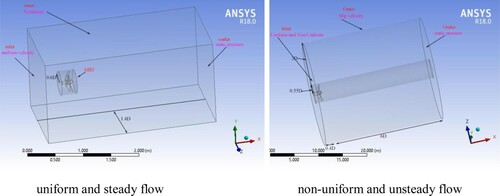
For unsteady state case, the inlet boundary is 0.4D with a uniform and non-uniform flow of velocity components, the outlet boundary in 6D with static pressure from the propeller centre and the outer boundary with 3D distance from the centre line of the shaft with boundary condition of slip velocity (Boumediene et al. Citation2019).
It should be mentioned that in the open-water condition, the standard k–ω model is selected for the steady case with MRF option is used, while in the unsteady and non-uniform wake, the k–ω SST model is selected with sliding mesh technique is employed. The time step corresponds to a rotation angle of 1 degree.
3.3. Mesh dependency
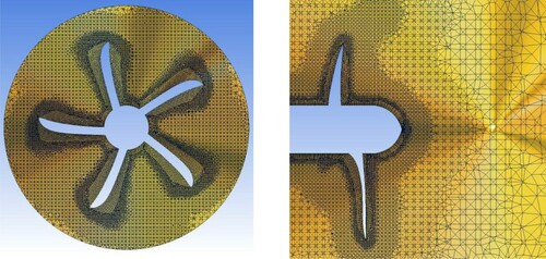
In the present research, the unstructured mesh is used because of its easier production than the structured mesh and the complexity of the geometry. The appropriate mesh at different cross-sections is shown in Figure . As shown in the figure, in areas where high velocity gradients are added to cell density, the mesh near the walls has become finer. The distance to the first computational cell from the walls is chosen such that the first value of the computational cell for the various walls in the computational domain is within the proper range for applying the standard wall function.
Figure 2. Mesh generation of the propeller.
The thrust and torque coefficients (,
) are compared in four mesh numbers (coarse, medium, fine and finer meshes) at the advance coefficient of 0.5. According to the results in Table , the final mesh with 2,834,796 computational cells and 715,488 nodes is considered for numerical simulations. The error with fine mesh is 0.93% for thrust coefficient and 1.76% for torque coefficient which are acceptable.
Table 2. Different meshes and dependency.
3.4. Open-water characteristics
In general, propeller design is influenced by four dimensionless quantities: advance, thrust and torque coefficient and propeller propulsion efficiency. The propeller hydrodynamic performance characteristic for different values of advance coefficient
are obtained using the ANSYS-CFX software based on the finite volume method. Finally, in order to validate the numerical simulation results, the obtained values will be compared with the experimental data.
For steady case simulation, a model of the Seiun–Maru series propeller with a scale of 1/9, a rotation and a diameter of propeller
is considered (Kadda Boumediene Citation2017). The characteristic curves of the propeller hydrodynamic performance are plotted in open water conditions for different advance ratio. The results of different simulations for validation are compared with the existing experimental results. The results of this study showed that the average error in the thrust and torque coefficients and efficiency were 5.7% and 3.9%, respectively. As shown in Figure , these results are in good agreement with the experimental results carried out by Ukon (Subramanian and Mueller Citation1995).
Figure 3. Comparison of open-water characteristics.
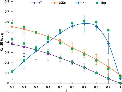
Considering the relative errors for the numerical values can be seen that the thrust coefficient , at least relative error of about 0.2% and the maximum relative error is 10.8%. By considering the relative error values of the torque coefficient (
), we find that the minimum relative error is 1% and the maximum relative error is 7.3%, which indicates a good overlap of the numerical results with the experimental data to predict the torque coefficient
.
3.5. Effect of wake flow
In the Cartesian coordinate system, the ,
,
Cartesian coordinate coefficients are in the
,
,
directions that the axial velocity, the tangential velocity and the radial velocity are the
propeller plane, the
propeller plane (positive in the direction of the propeller rotation) and the
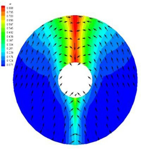
propeller plane (outward positive), respectively. The wake flow distribution for the full-scale propeller is shown in Figure .
Figure 4. Contour of wake flow applied to the propeller.
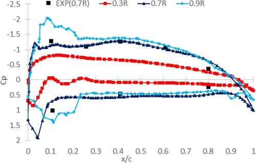
Pressure distribution is an essential to calculate the propeller performance. Because the propeller is a lifting body and pressure force is dominant to the shear stress force. Figure shows the pressure distribution at three radiuses (r/R = 0.3, 0.7 and 0.9) and compared with experimental data. Experimental results of Ukon at radius of 0.7R indicate good agreement with the present numerical results (Ukon et al. Citation1989).
Figure 5. Comparison of pressure distribution at different radiuses (J = 0.85).
For unsteady case simulation, a full-scale HSP propeller, a rotation and a diameter of propeller
is considered. Figure presented the comparison of thrust coefficient
of the one blade and whole blades during one cycle at J = 0.85. Green symbols of triangles show experimental results and solid lines show numerical results. The maximum error percentage for
is 5%. Figure presents the comparison of the torque coefficient
, one blade, and whole blades of the HSP propeller during one cycle at J = 0.85.
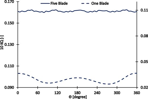
Figure 6. Comparison of thrust coefficient of the one blade and whole blades during one cycle (J = 0.85).
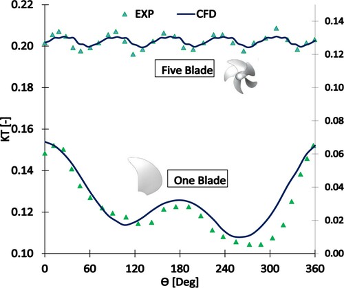
Figure 7. Comparison of torque coefficient of the one blade and whole blades during one cycle (J = 0.85).
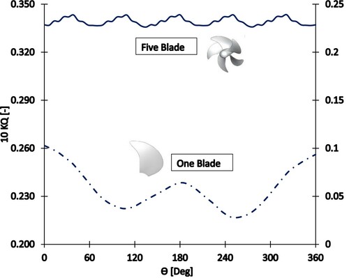
Figure presents the comparison of the thrust coefficient , one blade, and whole blades in the five-blade HSP propeller during one cycle at J = 0.6. Figure presents the comparison of the torque coefficient
, one blade, and whole blades in the five-blade HSP propeller during one cycle at J = 0.6.
Figure 8. Comparison of thrust coefficient of the one blade and whole blades during one cycle (J = 0.6).
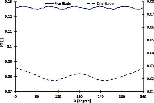
Figure 9. Comparison of torque coefficient of the one blade and whole blades during one cycle (J = 0.6).
3.6. Effect of cross-flow wake
In order to investigate the effect of cross-flow forces on thrust and torque coefficients, we examined the effects of three types of cross-flow wake onto the propeller defined as follows:
Wake 1: It is the same as the original one,
Wake 2: Vx is the same wake 1 but Vy and Vz components are increased by 20%,
Wake 3: Vx is the same wake 1 but Vy and Vz components are increased by 50%.
First, a comparison between the thrust and torque coefficients that include cross-flow wake effects is going to be presented in order to observe the differences between these cases.
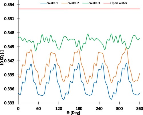
It means that the cross-flow wake is changed, the results of thrust and torque coefficients are calculated. Figures and show the total thrust and torque oscillating loads during one cycle at J = 0.85. Thrust is increased by 2.03% and 4.71% with wake 2 and wake 3, respectively. Torque is also increased by 1.04% with wake 2 and 2.69% with wake 3, respectively. All of them have five fluctuations during one cycle due to five blades.
Figure 10. Effect of the cross-flow wake on the total thrust coefficient during one cycle (J = 0.85).
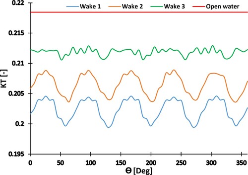
Figure 11. Effect of the cross-flow wake on the total torque coefficient during one cycle (J = 0.85).
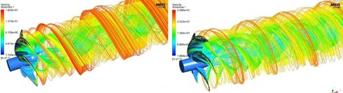
After studying the effect of wake changes on the propeller at two advance coefficients of 0.6 and 0.85, we compared the different positions of the five-blade HSP propeller in these two coefficients. The streamlines at the downstream of the five-blade propellers at j = 0.6 and 0.85 are presented in Figure . As shown in the figure, the velocity of the streamlines for the tip blades at J = 0.85 is greater than J = 0.6, and the number of streamlines for the hub area at J = 0.6 is greater than J = 0.85.
Figure 12. The streamlines at downstream of the three and five-blade HSP propellers.
4. Conclusion
The HSP propeller is analysed in open-water and non-uniform wake flow conditions. The effect of cross-flow wake was investigated. Based on the numerical results, the following conclusions can be drawn:
The comparisons of the present results and experimental data for the open-water characteristics are shown in good agreement.
Thrust coefficient is calculated during one cycle and agreed well with experimental data.
Regarding to increasing cross-flow wake, the oscillating thrust and torque are increased.
Present calculations employed the k–ω model with MRF in open-water condition and k–ω SST model with sliding mesh technique for wake flow.
By increasing the cross-flow wake 20% and 50%, the thrust at J = 0.85 are increased about 2.03% and 4.71%, respectively. Torque is also increased about 1.04% and 2.69%, respectively.
The oscillating thrust and torque of propeller due to the cross-flow wake is important because it is as forcing function force for analysing the propeller vibration. So, our next intent is to evaluate the propeller vibration by these propeller oscillating load.
Disclosure statement
No potential conflict of interest was reported by the author(s).
Additional information
Notes on contributors
Jabbar Firouzi
Jabbar Firouzi is a PhD candidate at department of maritime engineering - AUT in the field of marine hydrodynamics. His major field is marine propulsion and vibration. He has 20 years academic and industrial experiences in this field.
Hassan Ghassemi
Hassan Ghassemi is a professor of marine hydrodynamics at department of maritime engineering - AUT. His website is http://hmaa.itgo.com/ghassemi.html. He published more than 150 papers in the peer review journals and 10 books.
Karim Akbari Vakilabadi
Karim Akbari Vakilabadi is as assistant professor at department of mechanical engineering - Imam Khomeini marine university. His field is marine hydrodynamics and published many papers in this field.
References
- Bachant P, Wosnik M. 2015. Characterising the near-wake of a cross-flow turbine. J Turbul. 16(4):392–410.
- Boudreau M, Dumas G. 2017. Comparison of the wake recovery of the axial-flow and cross-flow turbine concepts. J Wind Eng Ind Aerodyn. 165(March):137–152.
- Boumediene K, Belhenniche SE, Imine O, Bouzit M. 2019. Computational hydrodynamic analysis of a highly skewed marine propeller. JNaval Archit Marine Eng. 16(1):21–32.
- Di Felice F, Felli M, Liefvendahl M, Svennberg U. 2009. Numerical and experimental analysis of the wake behavior of a generic submarine propeller. 1st Symposium on Marine Propulsors; June; Trondheim, Norway.
- Durante D, Dubbioso G, Testa C. 2013. Simplified hydrodynamic models for the analysis of marine propellers in a wake-field. J Hydrodyn. 25(6):954–965.
- Felli M, Camussi R, Di Felice F. 2011. Mechanisms of evolution of the propeller wake in the transition and far fields. J Fluid Mech. 682:5–53.
- Ghassemi H. 2009. The effect of wake flow and skew angle on the ship propeller performance. Sci Iran. 16(2 B):149–158.
- Ghasseni H, Ghadimi P. 2011. Numerical analysis of the high skew propeller of an underwater vehicle. J Mar Sci Appl. 10(3):289–299.
- Kadda Boumediene MB. 2017. Numerical flow simulation around HSP propeller in open water and behind a vessel wake using RANS CFD code. Int J Mech Mechatron Eng. 11(1):208–212.
- Menter FR. 1994. Two-equation eddy-viscosity turbulence models for engineering applications. AIAA J. 32(8):1598–1605.
- Moran-Guerrero A, Gonzalez-Gutierrez LM, Oliva-Remola A, Diaz-Ojeda HR. 2018. On the influence of transition modeling and crossflow effects on open water propeller simulations. Ocean Eng. 156(February):101–119.
- Okulov VL, Naumov IV, Mikkelsen RF, Sorensen JN. 2015. Wake effect on a uniform flow behind wind-turbine model. J Phys Conf Ser. 625(1). Conf. Ser. 625 012011 doi:10.1088/1742-6596/625/1/012011.
- Ortolani F, Dubbioso G, Muscari R, Mauro S, Di Mascio A. 2018. Experimental and numerical investigation of propeller loads in off-design conditions. J Marine Sci Eng. 6(2):45. 1–24.
- Phillips AB, Turnock SR, Furlong M. 2010. Accurate capture of propeller-rudder interaction using a coupled blade element momentum-RANS approach. Ship Technol Res. 57(2):128–139.
- Regener PB, Mirsadraee Y, Andersen P. 2018. Nominal vs. effective wake fields and their influence on propeller cavitation performance. J Marine Sci Eng. 6(2):1–14.
- Rijpkema D, Starke B, Bosschers J. 2013. Numerical simulation of propeller-hull interaction and determination of the effective wake field using a hybrid RANS-BEM approach. Third International Symposium on Marine Propulsors, smp’13; May. p. 421–429.
- Subramanian S, Mueller TJ. 1995. An experimental study of propeller noise due to cyclic flow distortion. J Sound Vib. 183(5):907–923.
- Tian Y, Kinnas SA. 2012. A wake model for the prediction of propeller performance at low advance ratios. Int J Rotating Mach. 2012:1–11.
- Ukon Y, Kurobe Y, Kudo T. 1989. Measurement of pressure distribution on a conventional and a highly skewed propeller model. J Soc Naval Archit Jpn. 165:83–94.
- Wang LZ, Guo CY, Su YM, Wu TC. 2018. A numerical study on the correlation between the evolution of propeller trailing vortex wake and skew of propellers. Int J Naval Archit Ocean Eng. 10(2):212–224.
- Yao H, Zhang H. 2017. Numerical studies of propeller exciting bearing forces under nonuniform ship’s nominal wake and the influence of cross flows. Shock Vib. 2017(2 b):1–15.
- Yari E, Ghassemi H. 2013. Numerical analysis of sheet cavitation on marine propellers, considering the effect of cross flow. Int J Naval Archit Ocean Eng. 5(4):546–558.