
 ?Mathematical formulae have been encoded as MathML and are displayed in this HTML version using MathJax in order to improve their display. Uncheck the box to turn MathJax off. This feature requires Javascript. Click on a formula to zoom.
Abstract
Silver (Ag) nanoparticles deposited sub–micro sized BaTiO3 particles (µBT) were fabricated as hybrid particles (Ag@µBT) to promote the dielectric response in a poly(vinylidene fluoride) (PVDF). The dielectric constant (ε′) of the Ag@µBT/PVDF composites continuously increased as the volume fraction (fAg@µBT) increased, while the loss tangent (tanδ) was effectively suppressed. The ε′∼173.49 was obtained in the composite with fAg@µBT=0.49, while a low tanδ was achieved (0.024), which was close to 0.021 for the PVDF. The Ag@µBT hybrid particles played essential roles in increased ε′ and inhibited conductive pathways, resulting in a low tanδ. The ε′ increased slightly, whereas tanδ changed significantly over the measured temperature range. Furthermore, ε′ was fitted with the effective medium percolation theory model. Therefore, the significantly improved dielectric properties were attributed to the high ε′ value of the µBT phase and interfacial polarization between the conductive Ag and insulating phases (i.e. µBT and PVDF).
Graphical Abstract
1. Introduction
In recent years, polymer dielectric materials have attracted attention for electronic applications [Citation1, Citation2]. Their excellent properties, especially flexibility, are more interesting than those of traditional ceramic dielectric materials [Citation3]. Poly(vinylidene fluoride) (PVDF) is an outstanding polymer because of its high dielectric constant (ε′≈10) [Citation4, Citation5], but it is still lower than that of ceramics [Citation6, Citation7]. Therefore, many researchers have investigated the dielectric properties (DPs) of PVDF.
Previous research has reported the enhancement of dielectric properties (DPs) of PVDF–based composites by introducing ceramics into the PVDF matrix [Citation8–11]. Interestingly, the results demonstrated an increase in these ε′ values. However, the ε′ values of the ceramic/PVDF composites remained low (ε′<100) for the PVDF composites with a high–volume fraction of ceramic filler (ffiller≥0.5). For CaCu3Ti4O12(CCTO)/PVDF and Ba(Fe0.5Nb0.5)O3/PVDF composites with ffiller = 0.5 [Citation12, Citation13], their ε′ values at 1 kHz were nearly the same in value (∼65), while their dielectric loss tangent (tanδ) values were ∼0.09 and ∼0.11, respectively. Therefore, this is a limitation of ceramic/PVDF composites [Citation14].
To overcome the problems of ceramic/PVDF composites, metal particles have been considered as fillers for PVDF–based composites [Citation15–17]. Metal particles with conductive properties can produce high ε′, which is related to the percolation effect. Therefore, a rapid increase in ε′ (>100) can be achieved, even in the case of a low ffiller. Unfortunately, the tanδ and conductivity (σ) of metal/PVDF composites are also high, which makes them unsuitable for capacitor devices [Citation18, Citation19]. For example, the ε′ value at 1 kHz of the Ag/PVDF composite with fAg = 0.22 can be increased to ∼275, while the tanδ value was very large (∼0.25) [Citation18].
Currently, researchers are interested in developing novel PVDF–based composites. The 3–phase PVDF composites incorporated with ceramics and metal particles are an interesting method for improving the DPs. The results showed that the DPs of the ceramic/metal/PVDF composites were better than those of the 2–phase PVDF composites. The ε′ rapidly increased while retaining low values of tanδ [Citation20–22]. For example, the ε′ value of the Na1/3Ca1/3Bi1/3Cu3Ti4O12(NCB)–Ni@NiO/PVDF composite with fNi@NiO = 0.2 (fNCB = 0.2) was significantly increased to ∼300 at 1 kHz, while the tanδ value was 0.17 [Citation23]. Although the Al-CCTO/epoxy composite with fAl = 0.2 (fCCTO = 0.2) can exhibit a high ε′ of ∼450 at 100 kHz, its tanδ value was also increased (∼0.024 at 100 kHz) [Citation24].
Most recently, a well–known method to enhance the DPs of 3–phase PVDF composites is filler surface modification [Citation25]. Hybrid particles are among the most common surface modifications. Metal particles deposited on the surface of ceramics have been synthesized to enhance ε′ and suppress tanδ values [Citation26, Citation27]. For fabricating hybrid particles, Ag nanoparticles were deposited on BaTiO3 with a particle size of ∼100 nm (Ag-nBT) [Citation27]. The ε′ and tanδ values at 1 kHz of the Ag@nBT/PVDF composite with fAg = 8.2 and fnBT = 48.6 was 160 and 0.11, respectively. When the volume fraction ratio of Ag and nBT was increased, both the ε′ and tanδ values significantly increased [Citation28]. The high ε′ originated from the space charge polarization at the interface between the hybrid particles and the PVDF. Another possibility is that hybrid particles can also cause interfacial polarization. Furthermore, because hybrid particles obstruct conductive pathways, a low tanδ value can be obtained. Thus, this increases the attraction of the 3–phase PVDF composites. Unfortunately, we observed that the tanδ values of these composites were still too large (>0.025), which may be unsuitable for capacitor applications. In our previous work [Citation29], although the DPs of the Ag@nBT/PVDF composites with isolated Ag and nBT could be improved, the tanδ value was quite large. The surface free energy of the nBT particles was higher than that of BT microparticles, resulting in a large agglomeration of nBT for reducing their surface free energies. This resulted in an increased tanδ value. On the other hand, BT microparticles are unsuitable for practical application in thin-film capacitor. Therefore, sub–micro sized BT particles (µBT) may be the best solution to overcome these limitations. Furthermore, a tetragonal phase is usually obtained in the µBT particles, while a cubic phase is usually observed in nBT. The ε′ value of a tetragonal µBT phase is higher than that of a cubic nBT phase. Therefore, the enhanced dielectric response in the polymer composites filled with µBT particles are expected. To the best of our knowledge, the DPs of PVDF–based composites filled with hybrid Ag@µBT particles and other metal@µBT hybrid particles have never been reported. Thus, the aim of this work is to fabricate PVDF composites filled with Ag@µBT hybrid particles to prevent the agglomeration of filler particles. High ε′ value and very low tanδ (<0.025) were expected. The Ag@µBT/PVDF composites may have potential for use in embedded capacitor technology and flexible thin-film capacitors.
In this work, we improved the DPs of the 3–phase PVDF composites, including BT and Ag, as hybrid particles. However, µBT particles were chosen because of their high ε′ compared to that of nBT particles. It is well known that the tetragonal structure of µBT is higher ε′ than the cubic structure in BT nanoparticles [Citation9, Citation30]. As a result, the Ag@µBT hybrid particles were expected to increase ε′ and decrease tanδ owing to the discrete growth of Ag nanoparticles on the µBT surface. Furthermore, the effect of the Ag–µBT hybrid particles on the DPs is discussed and explained. Ultimately, the results of this study could be useful in the electronics industry such as embedded and flexible thin-film capacitors.
2. Experimental details
2.1. Materials and preparation of Ag@µBT particles
Ethylene glycol (EG, QReC, 99.5%), µBT (0.5–2 µm, Sigma − Aldrich, 99.9% purity), and AgNO3 (RCI Labscan, 99.8%) were used to prepare the hybrid particles (Ag@µBT). A PVDF polymer (Sigma‒Aldrich, 99.9%) and absolute ethanol (EA, RCH Labscan, 99.5%) were used to fabricate the Ag@µBT/PVDF composites. Details of the preparation of Ag@µBT/PVDF composites have been explained in previous works [Citation19]. The ratio of µBT: AgNO3: EG was 5 g: 5 g: 300 mL.
2.2. Preparation of PVDF − based composites
First, PVDF and Ag@µBT powders with different volume fractions of Ag@µBT (fAg@µBT) were mixed in EA for 1 h using ZrO2 balls with different loadings of Ag@µBT fillers. Second, the ZrO2 balls were separated. Third, EA was evaporated at 100 °C for 24 h. Then, the mixture of the PVDF and Ag@µBT powders was carefully ground using mortar and pestle. Finally, the polymer composites powder was formed by hot–pressing for 0.5 h at 200 °C under ∼10 MPa. Furthermore, 2–phase µBT/PVDF composites with different volume fractions of µBT (fµBT) were also fabricated with the same method.
2.3. Dielectric measurement
First, the top and bottom surfaces of the composite samples were painted using silver paste. Next, the electrodes were dried at 80 °C for 24 h. Third, the room–temperature (RT) DPs were studied in the frequency range of 0.1 kHz to 1 MHz using a KEYSIGHT E4990 using the dielectric material test fixture 16451B. The Vrms was 0.5 V. Finally, the temperature dependence of the DPs was studied (30–150 °C) in the same frequency range.
2.4. Characterization techniques
The morphologies of the Ag@µBT particles were observed by field emission electron microscopy (FESEM, HITACHI SU − 8030) and transmission electron microscopy (TEM, FEI, TECNAI G2 20). FESEM was used to observe the dispersion of filler particles in the polymer matrix. X − ray diffraction (XRD, PANalytical, EMPYREAN) and Fourier transform infrared spectroscopy (FTIR, Bruker, TENSOR27) were used to identify phase compositions.
3. Results and discussion
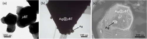
The morphologies of the µBT and Ag@µBT particles are displayed in , and the µBT particles (0.2–0.6 µm) are shown in . In addition, Figure1(b) and (c) illustrate the morphologies of the Ag@µBT particles. As can be seen, there are a few small spherical Ag nanoparticles with sizes of ∼10 − 50 nm. Therefore, Ag@µBT particles can be synthesized, and these particles are expected to enhance the DPs of the Ag@µBT/PVDF composites.
Figure 1. (a, b) TEM images of µBT and Ag@µBT particles, respectively. (c) FESEM image of Ag@µBT particles.
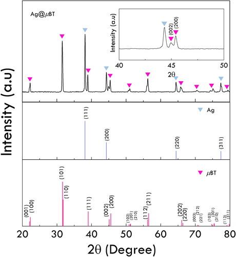
XRD was used to investigate the composition of the Ag@µBT particles, as shown in . The reference data for µBT displays double peaks at 2θ around 45°, which correspond to the (002) and (200) planes of µBT. These peaks indicate the tetragonal phase structure of the µBT. Moreover, the reference data for Ag illustrate four peaks of the (111), (200), (220), and (311) planes, which are located at 2θ = 38.1, 44.3, 64.5, and 77.4°, respectively. As can be seen, characteristic peaks of µBT and Ag appeared in the XRD pattern of Ag@µBT particles. This confirmed the deposition of Ag on the µBT surface. Therefore, the small particles in the TEM image are Ag particles. The inset figure shows peaks at 2θ ∼ 45° of the Ag@µBT particles, and double peaks of µBT can be observed. This indicates that the phase structure of µBT did not change after the hybrid particles were synthesized. Furthermore, the XRD Rietveld refinement showed the content of Ag = 37.90 wt% and µBT = 62.1 wt%.
Figure 2. XRD patterns of Ag@µBT particles compared to reference data of µBT and Ag.
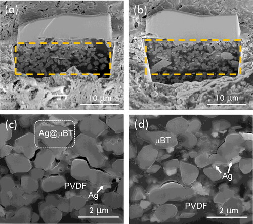
show the outer surface and inner morphologies (dashed rectangular area), which were prepared by removing the outer surface using focus ion beams, of the Ag@µBT/PVDF composites with fAg@µBT = 0.20 and 0.49, respectively. Therefore, the interiors of the polymer composites were examined by focusing the morphologies of the composites in the dashed rectangular area. Cross − section with a high magnification (35000X) of the composites fAg@µBT = 0.20 and 0.49 are displayed in , respectively. As can be seen, a good distribution of Ag@µBT particles was observed, and clusters of Ag@µBT particles were not revealed. The Ag@µBT particles are separated from each other by PVDF matrix. Therefore, a homogeneous distribution of the filler may contribute to better DPs of the polymer composite. Ag particles were observed, and there were clusters of Ag in the polymer composites without the connection of each Ag cluster. It is well known that a conductive pathway can occur owing to the agglomeration of metal particles. Therefore, it may result in a high tanδ and conductivity (σ).
Figure 3. SEM images of outer surface and inner layer (dashed rectangular area) of Ag@µBT/PVDF composites with (a, c) fAg@µBT = 0.20 and (b, d) fAg@µBT = 0.49.
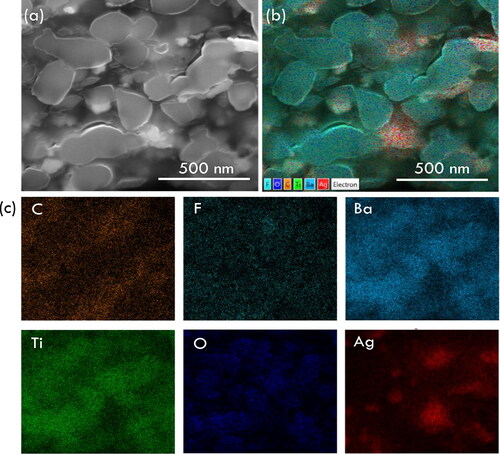
SEM–EDX mapping images of all elements in the composite with fAg@µBT = 0.49 are shown in . The results show the elements of PVDF, which are carbon (C) and fluorine (F). C and F are dispersed throughout the selected area, indicating the continuous phase of PVDF. Additionally, elemental mapping illustrates all the elements of µBT, including O, Ba, and Ti, with a homogeneous dispersion of µBT particles. In addition to the elements PVDF and µBT, Ag can be observed in red, and there are a few clusters of Ag particles. Therefore, the results can be used to confirm that µBT and Ag were introduced into PVDF.
Figure 4. (a) SEM image of selected area for elemental mapping of the Ag@µBT/PVDF composite with fAg@µBT = 0.49. (b) All mapping elements. (c) Mapping image of each element in the composities.
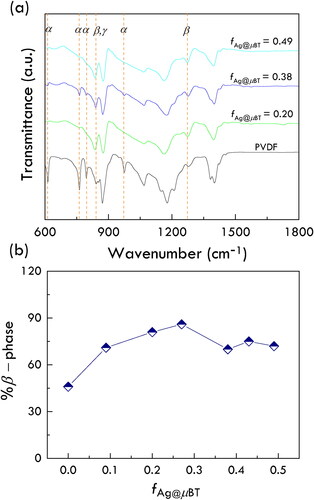
The phase conformations of the PVDF matrix and composites were studied using FTIR spectroscopy, as shown in , which shows the same phase conformation. The α−phase was confirmed to occur by the FTIR peaks at wavenumbers of 614, 766, 795, and 976 cm−1, which is a polar phase [Citation31–33]. Moreover, the wavenumbers at 840 and 1279 cm−1 indicate the characteristics of the polar phase β–phase [Citation31–33]. Another polar phase, the γ−phase, appeared at the same wavenumber as the β–phase (840 cm−1) [Citation31–33]. Therefore, the FTIR results indicated that both nonpolar and polar phases existed. The polar phase, especially the β–phase, may increase ε′ owing to the dipole–dipole polarization. Thus, the content of the β–phase is investigated using the Lambert − Beer equation as follows [Citation31]:
(1)
(1)
where Aα and Aβ are the absorbance of the α–phase at 766 cm−1 and the absorbance of the β–phase at 840 cm−1, respectively. The absorbance coefficients of the α– and β–phases are represented by Kα and Kβ, which are 6.1 × 10⁴ and 7.7 × 104 cm2 mol−1, respectively. EquationEq. (1)
(1)
(1) can be used to calculate assuming only the α– and β–phases in polymer composites. The β−phase composition (F(β)) is shown in . As can be seen, F(β) increased from 46% for PVDF to 86% for fAg@µBT = 0.27. However, F(β) decreased to 72% for fAg@µBT = 0.49. The increase in F(β) is the result of the addition of negatively charged particles to the polymer composites, which induces the formation of the all–trans (TTT) conformation of β–phase [Citation31]. In contrast, a high fraction of negatively charged particles can suppress β–phase formation, leading to a decrease in F(β) [Citation34].
Figure 5. (a) FTIR spectra of PVDF and the Ag@µBT/PVDF composites and (b) β−phase content of the Ag@µBT/PVDF composites with various fAg@µBT.
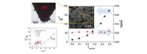
The dependence of the fraction of Ag@µBT particles on the DPs at 1 kHz of the Ag@µBT/PVDF composites compared to that of the µBT/PVDF composites is shown in . The trend of ε′ increased with increasing fAg@µBT and fµBT contents. The ε′ value of the 3–phase composite was larger than that of the 2–phase composite. This results clearly showed the important role of the hybrid particles. The interfacial polarization at the interfaces between insulator and conductor phases (Ag–µBT and Ag–PVDF interfaces) can cause the significantly increased dielectric response in the 3–phase composites [Citation27, Citation29, Citation35], while the primary contribution of the dielectric response in the 2–phase composites was resulted from a large ε′ value of the µBT particles [Citation36], as illustrated by the schematic representation in and (c). The highest ε′ value of the 3–phase composite was 173.49 for the composite with fAg@µBT = 0.49, which was significantly higher than that of the 2–phase composite (ε′∼100). The difference in dielectric responses owing to the effect of Ag particles increased with increasing filler volume fraction. The interparticle distance between adjacent hybrid particles was significantly shortened by increasing fAg@µBT. Thus, the thickness of the PVDF layer between the Ag particles was reduced, resulting in an increase in the capacitance of the microcapacitor [Citation37]. Furthermore, the increased interfacial area led to increased interfacial polarization and hence, ε′ values [Citation38]. As can be seen, ε′ increased by 13 times that of PVDF. Notably, a continuously increasing tanδ value was not observed as fAg@µBT increased.
Figure 6. (a) fAg@µBT and fµBT dependence of ε′and tanδ at 1 kHz and room temperature for the Ag@µBT/PVDF and µBT/PVDF composites. Schematic representation of the (b) Ag@µBT/PVDF and (c) µBT/PVDF composites.
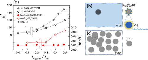
A tanδ value of 0.024 (1 kHz) was achieved in the composite with fAg@µBT = 0.49. The results show that the tanδ value of the composites was slightly changed compared to that of PVDF (tanδ = 0.021). Although the tanδ values of the 2–phase composites were still lower than 0.1, it is clearly seen that the tanδ value of the 3–phase composite was larger than that of the 2–phase composite. This result may be attributed to the improved dispersion of the hybrid particles in the PVDF matrix owing to the lower surface free energy caused by the deposited Ag particles [Citation29, Citation39], as illustrated by the schematic representation in and (c). The tanδ value of the Ag@µBT/PVDF composites remained low even when combined with the conductive–insulator Ag@µBT particles. The observed tanδ value indicates that the conduction pathway of the Ag particles did not form, which was inhibited by the µBT particles. Furthermore, the Ag nanoparticles were tightly attracted to the surface of the µBT particles. Hence, the possibility of large segregation of Ag nanoparticles to create a conduction pathway was effectively decreased. Nevertheless, the enhancement of ε′ may primarily originate from two factors: first, the space charge polarization at the interfaces between the Ag–PVDF and Ag–µBT, and second, the high ε′ of the µBT particles owing to its tetragonal phase structure. The ε′ and tanδ values at 1 kHz and RT are listed in . Notably, the excellent DPs of the 3–phase composite with fAg@µBT = 0.49 were obtained (ε′∼173.49 and tanδ∼0.024). The DPs of the Ag@µBT/PVDF composites in this current study are better than that of the Ag/nBT/PVDF composite with fAg+nBT = 0.521 (tanδ∼0.038) [Citation29]. At a filler volume fraction of ∼0.38, the ε′ value of the Ag@µBT/PVDF composite (∼103) was larger than that of the Ag/nBT/PVDF composite (∼83) [Citation29], while their tanδ values were 0.022 and 0.040, respectively. Furthermore, the DPs of the Ag@µBT/PVDF composites were significantly improved compared to that of the Ag@nBT/PVDF composite with fAg@nBT = 0.568 (ε′∼160 and tanδ∼0.11) [Citation27].
Table 1. Volume fractions of µBT (fµBT) and Ag (fAg) and dielectric parameters (ε′ and tanδ) of Ag@µBT/PVDF composites at RT and 1 kHz.
Furthermore, a two–phase µBT/PVDF composite with fµBT = 0.49 was also fabricated to study the dielectric properties compared to that of the three–phase Ag@µBT/PVDF composite with fAg@µBT = 0.49. The ε′ and tanδ values at 1 kHz of the two–phase µBT/PVDF composite were 118.47 and 0.040, respectively (not shown). Thus, the significantly improved DPs of the three–phase composites could be caused by the addition of Ag nanoparticles. Furthermore, the DPs of the Ag@µBT/PVDF composites were better than those of the same three–phase composite system filled with nBT. The ε′ and tanδ values at 1 kHz for the Ag@nBT/PVDF composite with fAg@nBT = 0.568 are 160 and 0.11, respectively [Citation27]. The ε′ and tanδ value of 0.50(MWCNTs/NBCTO)/PVDF composites were ∼401 and ∼1.71, respectively [Citation40].
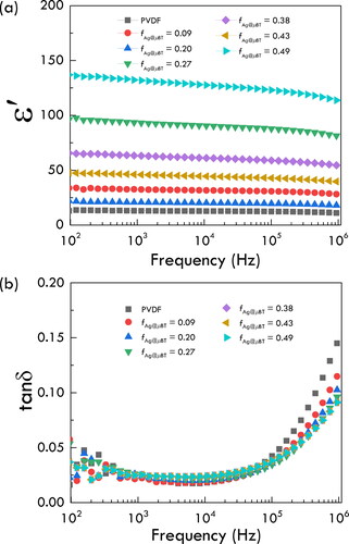
The DPs in the frequency range of 102–106 Hz were studied with various fAg@µBT values, as shown in . The ε′ value in the measured frequency range increases as the filler loading increases. The ε′ value of any composition decreased with increasing frequency, which can be observed at high frequencies. The decrease ε′ at high frequencies was due to the dielectric relaxation of the PVDF polymer. presents the frequency dependence of tanδ at RT. The tanδ value slightly decreased at low frequencies and then increased with increasing frequency. The behavior of tanδ at low and high frequencies can be described by the interfacial polarization effect and dielectric relaxation of the PVDF matrix, respectively.
Figure 7. Frequency dependence of (a) ε′ and (b) tanδ at RT for the Ag@µBT/PVDF composites with various fAg@µBT values.
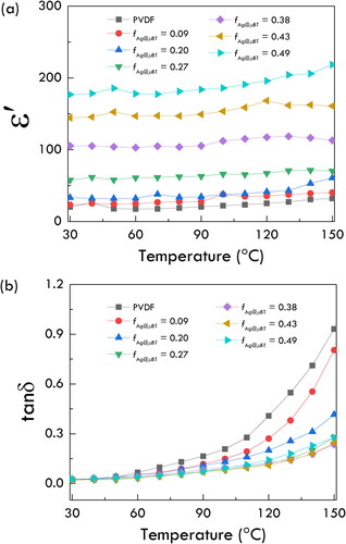
The temperature dependence of DPs has also received attention in the electronics industry. Therefore, the DPs of the Ag@µBT/PVDF composites were studied at temperatures ranging from 30 to 150 °C. As shown in , the ε′ of all samples increased slightly with increasing temperature. The ε′ of the Ag@µBT/PVDF composites at temperatures from 30 to 150 °C was associated with the motion of PVDF and interfacial polarization [Citation27, Citation41,Citation42]. Furthermore, as shown in , the tanδ tendency was enhanced at high temperatures, and the tanδ values of the Ag@µBT/PVDF composites were found to be lower than that of PVDF. The low tanδ value of high fAg@µBT could be explained by the restricted movement of the PVDF chains. However, the motion of PVDF chains with low fAg@µBT may be higher, resulting in a high tanδ [Citation43].
Figure 8. Temperature dependence of (a) ε′ and (b) tanδ at 1 kHz for Ag@µBT/PVDF composites with various fAg@µBT.
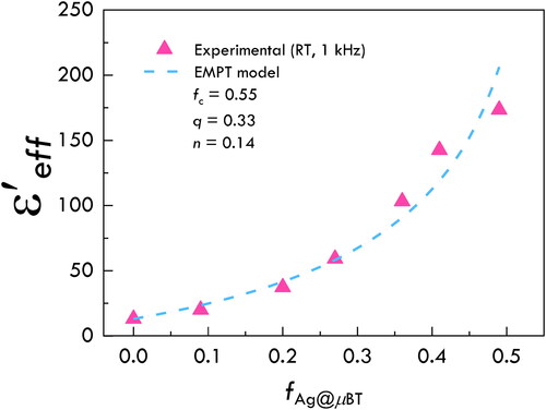
The dielectric behavior of the Ag@µBT/PVDF composites as a function of filler content was further studied using the effective medium percolation theory (EMPT) model. In general, the EMPT model is appropriate for ceramic–metal–polymer composites. Therefore, the Ag@µBT/PVDF composites were investigated using the EMPT model, which can be summarized as follows [Citation35]:
(2)
(2)
where
is the dielectric constant of the Ag@µBT/PVDF composite,
is the dielectric constant of BT (∼ 5000), and
is the dielectric permittivity of PVDF (13.03). fc denotes the percolation threshold. q and n are the critical component and filler morphology fitting factors, respectively. shows the fitted data for the experimental and EMPT models, EquationEq. (2)
(2)
(2) . The fitted data yield fc, q, and n values of 0.55, 0.33, and 0.14, respectively. It is interesting to note that n = 0.14 was close to the value of ceramic nanoparticles (n = 0.1–0.2) [Citation44]. The fitted fc of the Ag@µBT/PVDF composite was 0.55, while the highest fAg@µBT was 0.49. According to the fitted results, the enhanced dielectric properties were clearly confirmed to originate from the high ε′ of tetragonal µBT and the space charge polarization at the internal interface between the Ag–PVDF and Ag–µBT particles.
Figure 9. ε′ values at 1 kHz and RT for the Ag@µBT/PVDF composites fitted using the EMPT model.
4. Conclusions
The incorporation of the Ag@µBT hybrid particles improved the DPs of PVDF– composites. The microstructure of the Ag@µBT/PVDF composites revealed a good dispersion of Ag@µBT particles throughout the PVDF matrix. Elemental mapping confirmed the dispersion of µBT and Ag in the PVDF. Moreover, the content of the polar β–phase conformation increased from that of PVDF. It was also shown that the DPs of the three–phase composites were significantly improved compared with those of the two–phase µBT/PVDF composite. The ε′ increased to 173.49 and tanδ was 0.024 for the Ag@µBT/PVDF composite with fAg@µBT = 0.49. This demonstrates that a high ε′ can be achieved, while tanδ retains a low value. A low tanδ value indicated that there were no conductive pathways in the polymer composites. In addition, the Ag@µBT/PVDF composites with fAg@µBT = 0.49 were slightly affected by the temperature range of 30–150 °C. The fc of the Ag@µBT/PVDF composites was 0.55 when the data were fitted using the EMPT model. According to these studies, PVDF–based composites supplemented with Ag@µBT hybrid particles can be ideal polymer dielectric materials for electronic applications such as embedded and flexible thin-film capacitors.
Disclosure statement
No potential conflict of interest was reported by the authors.
Additional information
Funding
Notes on contributors
Kanyapak Silakaew
Kanyapak Silakaew obtained her Ph.D. from Khon Kaen University, Thailand, in 2020. She is currently a postdoctoral researcher in the Department of Physics at Khon Kaen University. Her research expertise is in polymer matrix nanocomposites.
Prasit Thongbai
Prasit Thongbai obtained his Ph.D. from Khon Kaen University, Thailand, in 2011. He is currently a Lecturer at Department of Physics, Khon Kaen University. His research expertise is in dielectric materials.
References
- Zhou T, Zha JW, Hou Y, et al. Surface-functionalized MWNTs with emeraldine base: preparation and improving dielectric properties of polymer nanocomposites. ACS Appl Mater Interfaces. 2011;3(12):4557–4560.
- Guan S, Li H, Zhao S, et al. Novel three-component nanocomposites with high dielectric permittivity and low dielectric loss co-filled by carboxyl-functionalized multi-walled nanotube and BaTiO3. Compos. Sci. Technol. 2018;158:79–85.
- Zhou W, Gong Y, Tu L, et al. Dielectric properties and thermal conductivity of core-shell structured Ni@NiO/poly(vinylidene fluoride) composites. J. Alloys Compd. 2017;693:1–8.
- Mao YP, Mao SY, Ye ZG, et al. Size-dependences of the dielectric and ferroelectric properties of BaTiO3/polyvinylidene fluoride nanocomposites. J. Appl. Phys. 2010;108(1):014102.
- Yang C, Song H-S, Liu D-B. Effect of coupling agents on the dielectric properties of CaCu3Ti4O12/PVDF composites. Compos. B. Eng. 2013;50:180–186.
- Xie Y, Yin S, Hashimoto T, et al. Sintering and dielectric properties of BaTiO3 prepared by a composite-hydroxide-mediated approach. Mater Res Bull. 2010;45(10):1345–1350.
- Jumpatam J, Putasaeng B, Chanlek N, et al. Significantly improving the giant dielectric properties of CaCu3Ti4O12 ceramics by co-doping with Sr2+ and F- ions. Mater Res Bull. 2021;133:111043.
- Tang H, Sodano HA. Ultra high energy density nanocomposite capacitors with fast discharge using Ba0.2Sr0.8TiO3 nanowires. Nano Lett. 2013;13(4):1373–1379.
- Fan B-H, Zha J-W, Wang D, et al. Size-dependent low-frequency dielectric properties in the BaTiO3/poly(vinylidene fluoride) nanocomposite films. Appl. Phys. Lett. 2012;100(1):012903.
- Wang Z, Wang T, Wang C, et al. Mechanism of enhanced dielectric performance in Ba(Fe 0.5 ta 0.5)O3/poly(vinylidene fluoride) nanocomposites. Ceram. Int. 2017;43:S244–S248.
- Sun C, Deng H, Ji W, et al. The effect of multilayered film structure on the dielectric properties of composites films based on P(VDF-HFP)/Ni(OH)2. Nanocomposites. 2019;5(1):36–48.
- Thomas P, Varughese KT, Dwarakanath K, et al. Dielectric properties of poly(vinylidene fluoride)/CaCu3Ti4O12 composites. Compos Sci Technol. 2010;70(3):539–545.
- Wang Z, Fang M, Li H, et al. Enhanced dielectric properties in poly(vinylidene fluoride) composites by nanosized Ba(Fe 0.5 Nb 0.5)O3 powders. Compos Sci Technol. 2015;117:410–416.
- Kum-Onsa P, Chanlek N, Thongbai P. Largely enhanced dielectric properties of TiO2-nanorods/poly(vinylidene fluoride) nanocomposites driven by enhanced interfacial areas. Nanocomposites. 2021;7(1):123–131.
- Wang L, Dang Z-M. Carbon nanotube composites with high dielectric constant at low percolation threshold. Appl. Phys. Lett. 2005;87(4):042903.
- Zheng W, Lu X, Wang W, et al. Fabrication of novel Ag nanowires/poly(vinylidene fluoride) nanocomposite film with high dielectric constant. Phys. stat. sol. (a). 2010;207(8):1870–1873.
- Zhou W, Chen Q, Sui X, et al. Enhanced thermal conductivity and dielectric properties of Al/β-SiCw/PVDF composites. Compos. Part A App.l Sci. Manuf. 2015;71:184–191.
- Phromviyo N, Chanlek N, Thongbai P, et al. Enhanced dielectric permittivity with retaining low loss in poly(vinylidene fluoride) by incorporating with Ag nanoparticles synthesized via hydrothermal method. Appl. Surf. Sci. 2018;446:59–65.
- Dang Z-M, Lin Y-H, Nan C-W. Novel ferroelectric polymer composites with high dielectric constants. Adv. Mater. 2003;15(19):1625–1629.
- Xie L, Huang X, Li BW, et al. Core-satellite Ag@BaTiO3 nanoassemblies for fabrication of polymer nanocomposites with high discharged energy density, high breakdown strength and low dielectric loss. Phys Chem Chem Phys. 2013;15(40):17560–17569.
- Su Y, Gu Y, Li H, et al. Ag-NBCTO-PVDF composites with enhanced dielectric properties. Mater. Lett. 2016;185:208–210.
- Chen G, Lin X, Li J, et al. Core-satellite ultra-small hybrid Ni@BT nanoparticles: a new route to enhanced energy storage capability of PVDF based nanocomposites. Appl. Surf. Sci. 2020;513:145877.
- Kum-onsa P, Phromviyo N, Thongbai P. Na1/3Ca1/3Bi1/3Cu3Ti4O12–Ni@NiO/poly(vinylidene fluoride): three–phase polymer composites with high dielectric permittivity and low loss tangent. Results Phys. 2020;18:103312.
- Shri Prakash B, Varma KBR. Dielectric behavior of CCTO/epoxy and Al-CCTO/epoxy composites. Compos Sci Technol. 2007;67(11–12):2363–2368.
- Gong L, Chen S-H, Zhan S-P, et al. An enhancement on the dielectric performance of poly(vinylidene fluoride)-based composite with graphene oxide-BaTiO 3 hybrid. Nanocomposites. 2019;5(2):61–66.
- Prateek D, Singh N, Singh AG, et al. Engineered thiol anchored Au-BaTiO3/PVDF polymer nanocomposite as efficient dielectric for electronic applications. Compos. Sci. Technol. 2019;174:158–168.
- Luo S, Yu S, Sun R, et al. Nano Ag-Deposited BaTiO3 hybrid particles as fillers for polymeric dielectric composites: toward high dielectric constant and suppressed loss. ACS Appl. Mater. Interfaces. 2014;6(1):176–182.
- Fang F, Yang W, Yu S, et al. Mechanism of high dielectric performance of polymer composites induced by BaTiO3-supporting Ag hybrid fillers. Appl. Phys. Lett. 2014;104(13):132909.
- Silakaew K, Chanlek N, Manyam J, et al. Highly enhanced frequency- and temperature-stability permittivity of three-phase poly(vinylidene-fluoride) nanocomposites with retaining low loss tangent and high permittivity. Results Phys. 2021;26:104410, 104410.
- Fan B-H, Zha J-W, Wang D-R, et al. Preparation and dielectric behaviors of thermoplastic and thermosetting polymer nanocomposite films containing BaTiO3 nanoparticles with different diameters. Compos Sci Technol. 2013;80:66–72.
- Martins P, Lopes AC, Lanceros-Mendez S. Electroactive phases of poly(vinylidene fluoride): determination, processing and applications. Prog. Polym. Sci. 2014;39(4):683–706.
- Cai X, Lei T, Sun D, et al. A critical analysis of the α, β and γ phases in poly(vinylidene fluoride) using FTIR. RSC Adv. 2017;7(25):15382–15389.
- Xia W, Zhang Z. PVDF‐based dielectric polymers and their applications in electronic materials. IET Nanodielectr. 2018;1(1):17–31.
- Thakur P, Kool A, Hoque NA, et al. Improving the thermal stability, electroactive β phase crystallization and dielectric constant of NiO nanoparticle/C–NiO nanocomposite embedded flexible poly(vinylidene fluoride) thin films. RSC Adv. 2016;6(31):26288–26299.
- Kum-onsa P, Phromviyo N, Thongbai P. Suppressing loss tangent with significantly enhanced dielectric permittivity of poly(vinylidene fluoride) by filling with Au-Na1/2Y1/2Cu3Ti4O12 hybrid particles. RSC Adv. 2020;10(66):40442–40449.
- Dang Z-M, Xu H-P, Wang H-Y. Significantly enhanced low-frequency dielectric permittivity in the BaTiO3/poly(vinylidene fluoride) nanocomposite. Appl. Phys. Lett. 2007;90(1):012901.
- Fu J, Hou Y, Wei Q, et al. Advanced FeTiNbO 6 /poly(vinylidene fluoride) composites with a high dielectric permittivity near the percolation threshold. J. Appl. Phys. 2015;118(23):235502.
- Meeporn K, Thongbai P, Yamwong T, et al. Greatly enhanced dielectric permittivity in La1.7 Sr0.3 NiO4 /poly(vinylidene fluoride) nanocomposites that retained a low loss tangent. RSC Adv. 2017;7(28):17128–17136.
- Silakaew K, Saijingwong W, Meeporn K, et al. Microelectron. Eng. 2015;146(Suppl. C):1–5.
- Su Y, Gu Y, Feng S. Composites of NBCTO/MWCNTs/PVDF with high dielectric permittivity and low dielectric loss. J Mater Sci: Mater Electron. 2018;29(3):2416–2420.
- Pan Z, Yao L, Zhai J, et al. Significantly improved dielectric properties and energy density of polymer nanocomposites via small loaded of BaTiO3 nanotubes. Compos. Sci. Technol. 2017;147:30–38.
- Zhou W, Kou Y, Yuan M, et al. Polymer composites filled with core@double-shell structured fillers: Effects of multiple shells on dielectric and thermal properties. Compos. Sci. Technol. 2019;181:107686.
- Lu X, Zou X, Shen J, et al. Characterizations of P(VDF-HFP)-BaTiO3 nanocomposite films fabricated by a spin-coating process. Ceram. Int. 2019;45(14):17758–17766.
- Yang W, Yu S, Sun R, et al. Electrical modulus analysis on the Ni/CCTO/PVDF system near the percolation threshold. J. Phys. D: Appl. Phys. 2011;44(47):475305.