
 ?Mathematical formulae have been encoded as MathML and are displayed in this HTML version using MathJax in order to improve their display. Uncheck the box to turn MathJax off. This feature requires Javascript. Click on a formula to zoom.
Abstract
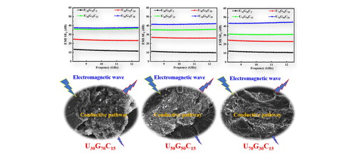
Polymeric composites with the hybrid filler network for high-performance electromagnetic interference (EMI) shielding brought increasing interest. Herein, UHMWPE/ground tire rubber (GTR)/conductive carbon black (CCB) (UGC) composites with a hybrid segregated structural CCB-GTR were constructed by solid-phase shear milling (S3M), mechanical blending, and compacted molding processes. The percolation behavior of electrical conductivity and EMI shielding effectiveness (SE) of composites was described using Sigmoidal/Growth models, and its EMI shielding mechanism was discussed. Results showed that the EMI SE of U30G70C20, U50G50C20, and U70G30C20 composites were found to be 37.5, 41.7, and 43.8 dB, respectively, due to constructing a hybrid network. The attenuation rate of microwave radiation is above 99.99%, and the shielding mechanism is mainly electrical loss. Moreover, the relationship between electrical conductivity and EMI SE is consistent with Sigmoidal/Growth models, indicating that Sigmoidal/Growth models can successfully predict the percolation threshold of the EMI SE of UGC composites.
Graphical Abstract
1. Introduction
Electrically conductive polymer composites (CPCs) containing rubber elastomers have a wide range of applications in flexible electronic devices, sensors, and electromagnetic interference, which has drawn broad attention from researchers [Citation1,Citation2]. However, what to do with these electrically conductive or anti-static rubber elastomer composites after use remains a question. Ground tire rubber (GTR) in particular is a composite made up of various elastomers, carbon black (CB), zinc oxide, stearic acid, processing oil, and other crosslinking agents. GTR materials have a three-dimensional cross-linking network structure, and at high temperature, even resembles a high-viscosity gel state. Therefore, such materials with three-dimensional structure for its recycling, reusing, and the application of compatibilization/toughening modification poses a giant challenge [Citation3–5]. Moreover, the processability and foamability of the obtained composites by waste GTR, the compatibility between thermoplastic polyethylene and GTR, and the functionality of polyethylene composites were very poor, as well as had all been extensively confirmed over the last few decades. Zhu et al. [Citation6] explored the machinability and foaming properties of LDPE/GTR blends by using solid-state shear milling equipment in a milling-disc type mechanochemical reactor and found that LDPE/GTR foam composites consist of GTR and LDPE powders shows better processability and foamability than those obtained by the traditional fusion mixing method. Simon-stronger et al. [Citation7] adopted the compatibilized strategy and blending modification for waste high density polyethylene (w-HDPE) and GTR to regenerate resources. Their studies revealed that waste GTR is frequently an insulator or semiconductor material, and when used as a filler alone to prepare composites, due to a major concern of poor compatibility between thermoplastic polyolefin and GTR is found in the prepared thermoplastic elastomer composites. So GTR is difficult to blend with polyolefin, the overall mechanical properties and conductive functional characteristics of these prepared composites are not ideal. Therefore, it is particularly crucial to use chemical or physical methods to modify the surface of GTR to enhance its compatibility with plastics and rubber, and to improve the mixing ability of GTR with polyolefin, so as to enhance the mechanical properties and conductive functional properties of these hybrid composites [Citation8–11].
In recent years, some studies discovered that GTR powder contained a lot of CB particles dispersed in the rubber matrix. When these GTR powders were added to the composites containing a conductive filler, as expected, they can be used as an additional CB conductive network in the composites to achieve the goal of reducing the dosage of conductive filler via the construction of a unique conductive channel, thus improving the electrically conductive property and electromagnetic shielding performance of composites. Furthermore, by combining GTR with high-conductivity carbon fillers, the filler can be restricted to enter the rubber matrix and distributed at the GTR interface to form the segregated structure [Citation12]. The concept of ‘segregated structure’ has been widely applied in various scientific fields, including crystal growth, gel elasticity, forest fire, morphological phase transition, powder compaction and prediction of electrical conductivity, thermal conductivity (TC), and mechanical enhancement of functional polymer composites [Citation13]. Therefore, this discovery provides good guidance for that industrial waste GTR can be converted into a valuable and high-performance electromagnetic shielding material.
According to the analysis of the classical percolation theory of filler networks, the primary reason for the poor shielding performance is the construction of the incomplete shielding network and the composites’ low electrical conductivity. Therefore, based on the percolation theory explored in our previous study of the content of the filler, the key lies in optimizing the conductive network, and how to theoretically predict the percolation behavior of the electromagnetic shielding efficiency of the composite system to achieve the ideal shielding performance [Citation14]. It is very critical to directly construct the high-effective and hybrid conductive network in composite structure through the combination of GTR and conductive filler to enhance the EMI SE of the composite [Citation15,Citation16]. Sheng et al. [Citation17] prepared an effective low micro-wave reflection EMI shielding material by incorporating nickel-coated ultra-high molecular weight polyethylene (UHMWPE @ Ni) particles into a tire rubber (GTR) matrix. The results show that when the Ni content is only 1.04 vol%, the EMI SE of the GTR/UHMWPE @ Ni composite can reach 47.3 dB at X-band. The reflectance power coefficient R of the composite is as low as 0.58 due to the synergistic effect of the Ni-CB hybrid networks, providing a feasible way to prepare efficient low microwave reflection electromagnetic shielding materials. Significant progress has been made in the functional and alloying of multi-component GTR [Citation12]. However, there is no published literature report on how to predict the threshold of EMI SE or the quantitative relationship between electrical conductivity and EMI SE of these CPCs, and how GTR components improve a better EMI SE and electromagnetic shielding mechanisms in CPCs [Citation18–20].
Based on this research background, the main goal of this paper is to study the percolation behavior of EMI SE of composites with different phase structures, as well as the internal relationship between electrical conductivity and EMI SE. Specifically, using UHMWPE/GTR with different mass ratios as the research object and CCB as the functional fillers, the CCB network with segregated structure was constructed in UHMWPE/GTR/CCB (UGC) composites by using solid phase shear milling technology (S3M), mechanical mixing and hot pressing technology. The influence of CCB content on the microstructure, electrical conductivity, electromagnetic parameters, EMI SE, and mechanical properties of UGC composites was studied systematically using SEM, DSC, TGA, Raman spectroscopy, four-probe resistance tester, vector network analyzer (VNA), and electronic universal testing machine. A Sigmoidal mathematical model was used to analyze the conductive percolation threshold and EMI SE percolation threshold of UGC composites to further reveal the functional relationship between conductivity and EMI SE of composites. Moreover, from this perspective of microscopic phase morphology, electromagnetic parameters, and electrical conductivity of composites, we also analyzed the electromagnetic shielding mechanism of the composites.
2. Materials and methods
2.1. Materials
Ground tire rubber (GTR, Guangzhou, China) was provided by Guangzhou Shilang Presix Ring Technology Co., Ltd. Conductive carbon black (CCB, F900A, Tianjin, China) was obtained from Tianjin Ebory Chemical Co., Ltd. UHMWPE (SLL-2, Shanghai, China) with an average molecular weight of 3.00 × 10⁶ g/mol, was purchased from Shanghai Lianle Chemical Industry Science and Technology Co., Ltd. All raw materials were used as received without further modification.
2.2. Preparation of UGC composites
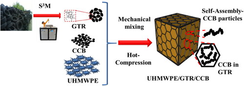
Firstly, the ultrafine grinding function of solid phase shear milling (S3M) technology was used to ground tire rubber three times to obtain GTR with a certain particle size distribution. Then, the prepared GTR was mechanically blended with UHMWPE particles. Three kinds of composites composed of UHMWPE70/GTR30, UHMWPE50/GTR50, and UHMWPE30/GTR70 were obtained by mechanical mixing and compacted molding method. The obtained blend is designated as UxGy, where x is the mass fraction of UHMWPE (70, 50, and 30 wt), and y is the mass fraction of GTR particles (30, 50, and 70 wt). On this basis, be named the abbreviation for UxGy as a matrix, with CCB as a conductive filler, mechanical blending combined with the molding method is used to prepare the conductive UGC composites, which are named UxGyCz, that is, the abbreviation is U70G30Cz, U50G50Cz, U30G70Cz. ‘z’ from 5 to 20 phr represents the content of CCB, which expressed in parts per hundred of the resin (phr). The preparation process of UGC composites is shown in .
Figure 1. Schematic of preparation of UGC segregated composites.
2.3. Characterization
The field-emission scanning electron microscope (FE-SEM, Regulus 8100, Hitachi, Japan) was carried out to analyze the morphologies and microstructures of UGC composites and UG blend. A confocal Raman spectrometer (Raman, DXR2xi, Thermo Scientific, USA) with a laser wavelength of 532 nm was used to collect Raman spectra of the samples. To confirm the composition analysis of GTR, its CB content, and inorganic fillers added amount in GTR, thermogravimetric analysis was performed (TGA, Q50, TA Instruments, USA) in a nitrogen atmosphere. The thermal properties of the before and after S3M GTR materials were performed on a Differential scanning calorimeter (DSC, Q20, TA Instruments, USA). The electrical conductivity value of composites was measured by using a piece of four-probe test equipment (RTS-9, Guangzhou Four Probe Technology Co. Ltd., China). The electromagnetic shielding properties for composites were measured vector network analyzer (VNA, N5244A, Agilent Technologies, USA) using the waveguide method at the X-band frequency range. The sheets of UGC and UG composites were cut into dumbbell-shaped specimens for the evaluation of the mechanical properties using a universal testing machine (CMT4104, Shenzhen Sans Material Inspection Co. Ltd., Shenzhen, China).
3. Results and discussion
3.1. Morphology and composition analysis of GTR before and after S3M grinding
The effect of S3M technology on the micromorphology of GTR particles is evaluated by SEM analysis. TGA and DSC are used to test the composition and structure changes of GTR as shown in . In Figure S1(a), GTR particles have larger particle sizes, and their particle size distribution range is 0.6–1.3 mm. In the high-magnification image, it can be observed that there are obvious microcracks on the surface of the GTR particles, and a large number of carbon black (CB) particles are uniformly dispersed in the GTR matrix. The size of the GTR particles after grinding 3 times gradually decreases due to the strong extrusion and shearing between the S3M grinding surfaces, and almost all of them become micron-sized powders with a particle size range of 100–150 µm, the surface of the milled GTR particles is rough, and the particles are composed of the irregularly shaped clusters as observed at high magnification image. The rougher surface helps the functional filler to adhere better to its surface during mechanical blending (Figure S1(b)). Additionally, to illustrate the content of inorganic components, such as CB in the milled GTR particles, TGA analysis was performed on the sample after three times S3M milling, as shown in Figure S1(c). From the TGA curve of the GTR, it can be seen that there is obvious weight loss at 381 °C, and the residue content at 700 °C is close to about 40%. These results indicated that the GTR contains close to 40% inorganics. Figure S1(d) shows that the glass transition temperature of the un-milled GTR and the samples after grinding three times did not change significantly, indicating a three-dimensional network structure inside the GTR is still maintained, which is the function of the CB-enhanced network structure.
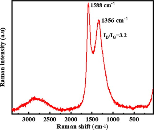
Raman spectroscopy was used to further validate the potential existing carbon black particle network in the milled GTR particles. In , the Raman spectrum has only two distinct characteristic peaks, and the Raman shifts are at 1356 and 1588 cm−1, this is mainly attributed to the Raman characteristic response peaks D and G bands of CB particles in GTR particles. The calculation of the ID/IG ratio of the GTR particles is 3.2, which indicates that the degree of graphitization of CB in the GTR particles is relatively low, and there are more amorphous carbon and microcrystalline defects in the milled GTR particles. It shows that GTR has low electrical properties. In summary, the Raman spectral signals of the CB components in the milled GTR particles respond significantly, which confirms that the GTR particles after three times of milling still have an existing CB-enhanced network with a three-dimensional network structure.
Figure 2. Raman spectrum of GTR after grinding for three cycles.
3.2. Microstructure of UGC and UG composites
The effect of fillers on the coarsening of phase morphology can be determined by fillers concentration at the interface. Therefore, to further explain the stabilization of the conductive phase by adding CCB particles in UG composites, the distribution of CCB particles reduces the interfacial tension that can be explained according to the principle of minimum interfacial energy. Nano-particles act as a barrier at the interface, the viscosity and elasticity of the nanoparticle-containing polymer phase are increased, or the viscoelasticity of the polymer is improved synergistically to inhibit filler agglomeration, resulting in a randomly fragmented dispersed phase. Thereby, filler coarsening, functionalization, and self-assembled networks of particles in polymer matrices are effective factors [Citation21–24]. We studied the microstructure of UG composites with different mass ratios. show the brittle fracture micro-morphologies of U30G70, U50G50, and U70G30 composites. In , there are no obvious interfacial defects in the two phases of the U30G70 composite, and the interface is relatively blurred. UHMWPE particles with small domains are well embedded between GTR particles and are closely surrounded by the GTR particles, thus forming a typical segregated structure. The two-phase domains of the U50G50 composite are significantly refined as the UHWMPE component content increased to 50 wt%, the phase interface was blurred, a typical co-continuous structure was formed, and a significant phase transition occurred as presented in . In , when UHMWPE content is 70 wt%, U70G30 composite has the phenomenon of coarse-grained UHMWPE domains again, and the two-phase interface is more obvious, and the GTR particles are displaced to the interface between the UHMWPE particles, forming a sea-island morphology of the segregated structure is in contrast to the above-mentioned studies of the domain breakup mechanism. Therefore, this phase transition phenomenon provides the possibility to realize the dielectric and conductive properties of UG composites under the low loading of CCB.
Figure 3. SEM micromorphology of UG Compound and UGC composites with 5 phr CCB content: U30G70 (a), U50G50 (b), U70G30 (c), U30G70C5 (a1), U50G50C5 (b1), U70G30C5 (c1). the red circle area is the SEM× 5k magnification images of the corresponding composites.
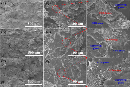
To confirm the compositional advantages of an electromagnetic shielding material with a hybrid phase structure, the microstructure of the brittle section of U30G70C5, U50G50C5, and U70G30C5 composites was analyzed by SEM. show the microstructure of the brittle section of U30G70C5, U50G50C5, and U70G30C5 composites. It was found that the hybrid CCB-GTR network in U30G70 composites, which contains only 5 phr CCB, enables the construction of a continuous conductive network with the CCB distribution layers connected by the phase components between UHMWPE and GTR regions, as shown in . The high magnification could also be observed. In , the CCB layer of the UGC composite containing 5phr CCB is relatively thin, and the CCB particles have obvious selective distribution into the GTR particle matrix. The selective distribution phenomenon also occurs in the U30G70C5 and U70G30C5 composites as shown in enlarged views of (the red line refers to the right parts). Furthermore, in , U70G30C5 composite does not form a continuous conductive pathway due to the existence of many interface defects between UHMWPE and GTR particles, as well as a large number of voids. In comparison to U30G70C5 and U50G50C5 composites, the CCB layer of U30G70C5 composite is thinner between the UHMWPE and GTR regions, indicating that co-continuous structure is advantageous for constructing in the U30G70 matrix with the higher content of soft-phase GTR components and U50G50. In addition, the CCB segregated network is constructed, whereas in U70G30 with the more hard-phase UHMWPE, the CCB particles are difficult to enter the interior of the UHMWPE matrix and can only be segregated and distributed at the interface of the UHMWPE particle microdomain, resulting in the composites with the same content of CCB exhibit thin layer channel, and thereby forms an insufficiently conductive network. This is mainly attributed to the preferential distribution of carbon black particles inside and at the GTR spaces leading to changes in UHMWPE chain dynamics, thereby changing the phase morphology of the blends, independent of the UG mass ratio. Figure S2 depicts the microstructure of U30G70C10 (Figure S2(a)), U50G50C10 (Figure S2(b)), U70G30C10 (Figure S2(c)) composites with 10 phr CCB content. As can be seen from , there is also a component advantage in building functional networks in the U50G50 and U30G70 matrices with high GTR content. The connectivity of the segregated structures in the U30G70C10 and U50G50C10 composites is significantly higher than in the U70G30C10. This above supports the results of SEM observations, in which a continuous conductive network was not well constructed in a composite of 70/30 wt UG compounds. This is primarily due to the non-polarity, high viscosity, and surface chemical properties of UHMWPE materials, which can cause CCB particles to be squeezed only toward the interface between UHMWPE particles.
3.3. Electrical conductivity
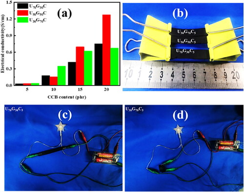
To confirm the stability and high efficiency of the conductive network construction, shows the effect of different CCB additions on the electrical conductivity of U70G30C, U50G50C, and U30G70C composites. From , it was evident that the electrical conductivity of U70G30C, U50G50C, and U30G70C composites was improved with the increase of CCB content. When the CCB content is 10 phr, the changes law of electrical conductivity of U70G30C, U50G50C, and U30G70C composites: U30G70C10 > U50G50C10 > U70G30C10. U30G70C10 composite has an electrical conductivity of 0.35 S/cm, which is 2.06 times that of U70G30C10 (0.17 S/cm) and 2.18 times that of U50G50C10 (0.16 S/cm), which fully meets the conductivity requirements of commonly used electromagnetic shielding materials (0.01 S/cm). Moreover, the electrical conductivity of the three UGC composites increased significantly when the CCB content was increased by 15 phr, with the increased range being U50G50C15 > U30G70C15 > U70G30C15. When the CCB content was further increased to 20 phr, the electrical conductivity of U50G50C20 composite is 1.27 S/cm, which is 1.75 times that of U70G30C20 (0.75 S/cm) and 1.88 times that of U30G70C20 (0.68 S/cm). The sharp increase in the conductivity of the U50G50C20 composite is mainly attributed to the formation of its continuous segregated structure. Furthermore, to verify that the prepared composite material has certain flexibility and conductivity, a rectangular spline of U70G30C5 composite is assembled into a circuit, and the LED light in the circuit was successfully lit. Additionally, the U50G50C5 composite sample was bent into a ring-shaped assembly circuit, and the LED lights in the circuit were also successfully lit, and the luminous brightness was very close to that of the U70G30C5 composite as presented in . These results show that the conductive composite has excellent electrical conductivity and flexibility.
Figure 4. (a) Influence of the different CCB additions on the electrical properties of U70G30C, U50G50C, and U30G70C composites, (b–d) UGC composite sample and assembled LED circuit diagram.
3.4. Electromagnetic parameters
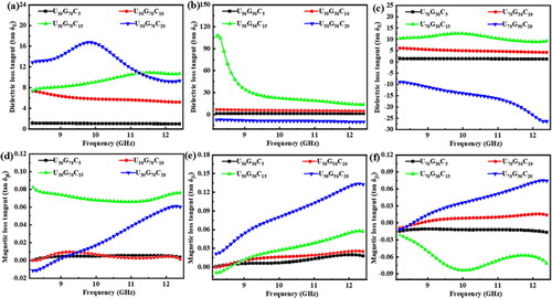
U70G30C20, U50G50C20, and U30G70C20 are three kinds of composites that have excellent electrical conductivity according to the above analysis of electrical conductivity. In addition to electrical conductivity, dielectric loss, and magnetic loss capability are key parameters that determine electromagnetic radiation shielding as an electromagnetic shielding material. Thus, furtherly analyzing the electromagnetic parameters, such as complex permittivity (ε) and complex permeability (μ), we investigate the effect of CCB additions on the dielectric loss factor, magnetic loss factor, and electromagnetic shielding mechanism of UGC composites in the X-band, and obtain the dielectric loss factor tan δε = ε″/ε′ and magnetic loss factor tan δμ = μ″/μ′. demonstrates that UGC composites with varying CCB dosages have similar dielectric loss and magnetic loss factors. The tan δε of the above three composites gradually increased as the CCB content increased. This outcome indicates that as conductive fillers are added, the dielectric loss of UGC composites increases, resulting in an improvement in EMI SE. clearly shows that the dielectric loss of the U70G30C composite is increasing in the X-band. At low frequencies, the dielectric loss peaks around 10 GHz, indicating that the composite has good dielectric loss capability. Therefore, as the CCB content increases, the dielectric loss becomes the primary reason for the improvement of the EMI SE. This is ascribed to the interfacial polarization effect [also known as Maxwell–Wagner–Sillar (MWS) effect], which is a common phenomenon in heterogeneous polymer composites with varying electrical conductivity or actual dielectric constant [Citation25]. This effect frequently happens on the mesoscopic scale at the interfaces of different phases with different electrical conductivity or dielectric constant due to the accumulation of many charge carriers. Therefore, according to the MWS effect, for our prepared composites, interfacial polarization usually occurs on a large scale (mesoscopic scale, see SEM magnification images), and its relaxation time relative to the electric field frequency is large at high frequencies, so it is usually observed at low frequencies. These results can observe in the above-mentioned of SEM morphology of the mesoscopic scale of the insulating layers, such as UHMWPE and GTR, which have been introduced to prevent the direct contact of CCB particles assembled network in composites, consequently reducing the dielectric loss and maintaining a relatively high interfacial polarization ability. Moreover, all polarization mechanisms may contribute to dielectric loss, and the larger the interface polarization scale, the more significant its effect [Citation26]. This mechanism of interfacial relaxation can result in a decreasing trend of dielectric loss as a function of frequency with increasing frequency, and thus its dielectric property could be interpreted by the formation of abundant nanocapacitors within the composites and the interfacial polarization effect resulting from the accumulation of charge carriers at the internal interfaces between CCB and UG, which is consistent with the results reported in the existing literature [Citation27–29]. In , the dielectric loss of the composite decreases gradually with the increase of the CCB content, and even the U70G30C composite shows a sudden change from a positive value to a negative value as increased with frequency, which belongs to the typical anti-resonance behavior. This appearance of anti-resonance behavior is primarily due to the existence of additional interfaces in UGC composites with different microstructures, as well as the varying interfacial electrical property between UHMWPE-GTR, UHMWPE-CCB, GTR-CCB. This generated difference can be used for nanocapacitors that enhance the electrical property of composites [Citation30]. Another reason is that the electric dipoles in UGC composites are too slow to respond to high-frequency radiation, causing them to lag behind the applied microwave field [Citation31]. This is related to the low-frequency relaxation, and the interfacial polarization phenomenon occurs at the interfaces between CCB and matrix. In , the tan δμ of all UGC composites is <0.15, and has little relationship with the CCB content, indicating that the UGC composite is a non-magnetic conductive material with low magnetic loss. But it is worth noting that U50G50C composite has the highest magnetic loss factor and better magnetic loss ability as compared with U30G70C and U70G30C composites. This could be due to the fact that co-continuous U50G50C composite will generate a magnetically induced current in the alternating electromagnetic field, thereby forming a certain eddy current loss and causing a large magnetic loss (see ).
Figure 5. Influence of CCB content on dielectric loss (tan δε VS CCB content) of U30G70C, U50G50C, and U70G30C composites (a–c), and influence of CCB content on magnetic loss (tan δμ VS CCB content) of U30G70C, U50G50C, and U70G30C composites (d–f).
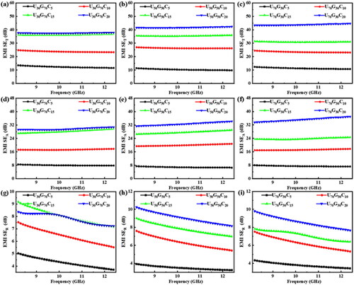
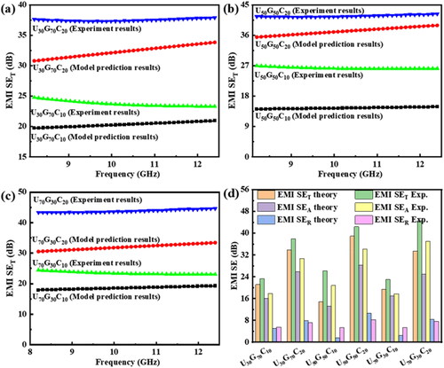
depicts the effect of CCB addition on the total EMI shielding effectiveness (EMI SET), absorption loss (EMI SEA), and reflection loss (EMI SER) of UGC composites in the X-band. When the CCB content was 20 phr (mass fraction 16.67% wt%), the EMI SET and EMI SEA of UGC composites increased with the increase of CCB content. In , the average EMI SET of U30G70C20, U50G50C20, and U70G30C20 composites are 37.5, 41.7, and 43.8 dB, respectively, with a microwave attenuation capability of 99.99%, and the EMI SET of U70G30C20 composites are higher than that of U30G70C20 and U50G50C20 composites. It is demonstrated that the electrical conductivity of the UGC composite is not the only factor that influences the EMI SET. In , the average EMI SEA of U30G70C20, U50G50C20, and U70G30C20 composites are 29.7, 32.6, and 35.2 dB, respectively. Furthermore, the EMI SER of all UGC composites increased slowly with the increase of CCB content, and the EMI SEA is much higher than the EMI SER, indicating that the effect of UGC composites on microwave attenuation was primarily due to EMI SEA contribution. Moreover, we compared some CNTs/polymer composites with the hybrid segregated structure recently reported in the literature, it is found that our prepared UGC composites possess an acceptable EMI ability (see Tables S1 and S2).
Figure 6. Influence of CCB content on EMI SE (EMI SET VS CCB content) (a–c), (EMI SEA VS CCB content) (d–f), and (EMI SER VS CCB content) (g–i) of U30G70C, U50G50C, and U70G30C composites in X-band.
Based on the above changes in the complex permittivity and complex permeability of the UGC composite, the investigation of its electromagnetic shielding mechanism and the theoretical value of the EMI SE of the composite by CCB content are discussed and analyzed. It was observed that the EMI SE of UGC composite was highly correlated with the CCB content. When the CCB content was 5–10 phr, the EMI SE exhibited obvious percolation behavior, and the shielding mechanism was primarily electrical loss as shown in . However, the EMI SET of UGC composites is mainly composed of EMI SEA, EMI SER, and EMI SEM according to Schelkunoff’s electromagnetic shielding theory [Citation32,Citation33]. When EMI SET is >10 dB, EMI SEM can usually be ignored. Given that the current existing characterization tools cannot evaluate the multiple reflection effect alone, the effects of absorption and reflection on EMI SE and the shielding mechanism of UGC composites with different phase morphologies were studied in greater detail using data from a vector network analysis test equipment (VNA). The data for the power coefficients R, A, and T are analyzed, and multiple reflection effects have been excluded from the discussion in this section. T and R are directly measured by the VNA characterization device. Assuming a constant incident power (PIN = 1 mW), A can be calculated, that is, A = 1 − (T + R), and the measured reflected power R is not only the power reflected from the outer surface but also the reflected power from the inner surface. Positive and negative contributions must come from multiple reflections.
Figure 7. Influence of CCB concentration on reflection coefficient (R), absorption coefficient (A), transmission coefficient (T) (a–c), and EMI SE of U30G70C, U50G50C, and U70G30C composites at 12.4 GHz (d–f).
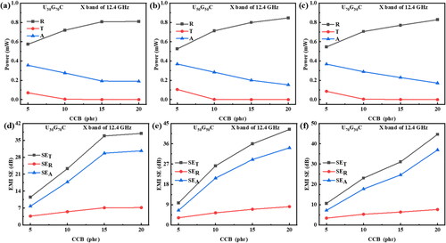
From , it is observed that the value of A of UGC composites decreases significantly with the increase of CCB content. While R shows the opposite trend, which is related to the increase in the electrical conductivity of the UGC composites. Obviously knowing that the R value is higher than the A value, it would be inappropriate to assume that reflection is the main shielding mechanism. The low A value is due to the fact that better reflection results in a small amount of power being transferred into the UGC composite, therefore, measuring the contribution of absorption to the overall shielding should be based on the shielding material’s ability to attenuate un-reflected power, whereas EMI SE is a relative. The amount is independent of the absolute power value. Therefore, considering the relative amount of EMI SE, the most widely accepted method for evaluating absorption contribution is based on the ability of attenuating microwave power to penetrate the material, and using the ratio of the A value to the incident power (PIN) to evaluate the absorption is a more reasonable method [Citation34]. Furthermore, the T value is much lower than the A and R values, indicating that almost no microwave power escapes from the inner layer of the shielding material, and these prepared UGC composites have good shielding properties (see ). The composites’ electrical conductivity, thickness, surface morphology, and uniformity all have an impact on shielding properties. To further illustrate the contribution of the above-mentioned reflection loss EMI SER and absorption loss EMI SEA to the total EMI SE, we analyzed the EMI SER and EMI SEA of U30G70C, U50G50C, and U70G30C composites at 12.4 GHz, as shown in . All UGC composites’ EMI SEA is much higher than EMI SER, thus confirming that the enhancement of EMI SE is mainly caused by EMI SEA. To explore the electromagnetic shielding mechanism, we try to carry out a theoretical analysis to better understand the electromagnetic shielding ability of the double-percolation segregated structure UGC.
However, there is no electromagnetic wave shielding theory for multiphase heterostructure shielding materials at present. We use the electromagnetic shielding theory of traditional uniform conductive material systems to obtain some enlightenment [Citation35]. For uniformly conductive materials, shielding theory is mainly used to further explain and quantify the contribution of EMI SER and EMI SEA to the overall EMI SE as a function of conductivity. The theoretical calculation formula is as follows [Citation36–39]:
(1)
(1)
(2)
(2)
Where f is the frequency of the electromagnetic wave; μ is the permeability of the material, μ = μ0μr, μ0 = 4π × 10−7 H/m, the absolute permeability of the free space, μr is the relative permeability of the material; d is the thickness of the sample; σ is the electrical conductivity of the shielding material. The EMI SE is anticipated to use the aforementioned formula by the theoretical study mentioned above. The electrical conductivity of the UGC composites used in the theoretical prediction analysis of EMI SE is the direct current electrical conductivity of UGC10 and UGC20 composites as measured by the four-probe test. The change law of UGC10 and UGC20 composites between the theoretical prediction of EMI SE and the actual test was presented in and Table S1. Comparative investigation revealed that as CCB content rises, both the theoretical EMI SE value and the experimental EMI SE of UGC increase. The EMI SE obtained from the test is larger than those predicted by theory. The experimentally tested EMI SET and EMI SEA at 12.4 GHz for all UGC composites are higher than the theoretically predicted values. However, comparing the reflection loss EMI SER of UGC composites, the variation law is a bit more complicated in Table S3. Moreover, the theoretical EMI SER values of U30G70C10, U50G50C10, and U70G30C10 are all smaller than the experimental real values. Whereas, in other UGC, all theoretically predicted EMI SER values are larger than the experimental real results. For example, the theoretical SER of the U70G30C20 composite is 8.4 dB, and the corresponding experimental value is 7.6 dB. From the results of the above analysis, there seems to be a conflict between the theory and experiments of UGC composites. As mentioned earlier, the above formula is only used to predict the EMI SE of uniformly EMI shielding materials. In addition, a large number of UHMWPE-CCB, GTR-CCB, and UHMWPE-GTR interfaces are formed in the multiphase heterostructure for the current composites, and thereby its shielding mechanism is relatively complicated.
Figure 8. EMI SET values between theoretical predictions and experimental results of U30G70C, U50G50C, and U70G30C composites with different CCB content in X-band (a–c), comparison of EMI SET values for U30G70C, U50G50C, and U70G30C composites (d).
The percolation threshold in percolation behavior is generally considered to be the critical concentration of the first continuous conductive network of filler particles in the shielding material of CPCs, as well as the first continuous conductive network, for a given nanocomposites. Understanding the specific percolation process and determining the quality of the filler network is therefore crucial. These fillers assembled networks can interact with incoming electromagnetic radiation and potentially absorb it, effectively acting as a shield effect. Furthermore, the polymer-filled composite system transforms from an insulator to a conductor at the percolation threshold. Above the conductive percolation threshold, the addition of fillers results in finer pore sizes, closing the gaps through which electromagnetic radiation can pass, resulting in a denser and stronger conductive network in the composite without leaving discontinuities and any space in interfacial regions, thereby improving the EMI SE of the composite material and has good shielding layer properties. This structural feature is mainly noticeable when the filling rate of functional fillers in the composite material is high as shown in Figure S3. As previously stated, the EMI SE of polymer composites containing conductive carbon materials, like that of CPCs, goes through a transition stage known as the percolation threshold. To fit and analyze the EMI SE percolation threshold and electrical conductivity percolation threshold of U30G70C, U50G50C, and U70G30C composites, various Sigmoidal Models (Sigmoidal Models) such as Sigmoidal-Boltzmann (SB), Sigmoidal-dose response (SD), Sigmoidal-Hill (SH), and Sigmoidal-logistic (SL) were used. SB model is widely used in the phase transition of smart gels, and RF magnetron co-sputtering in thin film deposition. SB can be defined as [Citation18,Citation19,Citation40,Citation41]:
(3)
(3)
Where ‘Y’ is the EMI SE of the filler at the volume fraction of ‘x’. ‘x’ is an independent variable. A1 and A2 are the lowest and highest values of the electrical characteristics, respectively. ‘Δx’ represents the slope, which represents the gradient of the curve. ‘x0’ represents the x-axis relative to values like the y-axis is represented by (A1 + A2)/2.
SD model is used in the study of soil ecotoxicology, biological assays, and radioligand assays to draw physiological curves and studies on the effects of pyrite sludge pollution on soil enzymes. SD can be expressed as:
(4)
(4)
In this mathematical model formula, A1 and A2 represent the initial value (lowest) and final value (highest) of EMI SE, respectively. ‘log x0’ is the middle value of the lowest value and the highest value of EMI SE on the y-axis, and P represents the slope, indicating that at ‘log x0’. The gradient of a curve is also known as the slope factor or slope. In the case of standard dose-response curves, the slope factor values are uniform. When the slope value is above unity, the curve appears steeper, and logx0 is a measure of the percolation threshold.
SH model is widely used in the field of ‘T’ lymphocyte and helper cell dynamics in human immunodeficiency virus infection. SH can be written as:
(5)
(5)
Where ‘Y’ represents the relevant parameters of ‘x’ under all volume fractions, and x is an independent parameter; ‘A1’ and ‘A2’ are the initial and final values of the electrical characteristics, respectively; ‘n’ is the Hill coefficient, also known as the Hill slope/shape factor, which means gradient of the curve; ‘k’ represents the value of filler content on the x-axis relative to the corresponding y-axis value (A1 + A2)/2. The percolation threshold can be expressed as:
(6)
(6)
SL model is applied to the variability of forces during successive isometric contractions, plant growth, phenological models, and high-temperature anaerobic digestion of methane [216]. SL can be defined as:
(7)
(7)
In the SL model’s math formula, ‘Y’ is the relevant parameters of the electrical properties when the filler is added with ‘x’; ‘A1’ and ‘A2’ are the initial and final values of the electrical properties, respectively; ‘x0’ represents the middle value of the lowest and highest response, the unit is the same as ‘x’, ‘P’ represents the gradient of the slope, is also known as slope factor (>1). The percolation threshold can be expressed as:
(8)
(8)
Figure S3 shows model fitting, experimental, theoretical data, and derivative curves based on SB, SD, SH, and SL. According to the fitted graphs of the SB, SD, SH, and SL models, it can be seen that the SB and SD models predict similar electrical conductivity percolation thresholds, which can be attributed to the similar values of the y-axis parameters of the two models at the percolation thresholds, this is, the percolation thresholds are equal to (A1 + A2)/2.
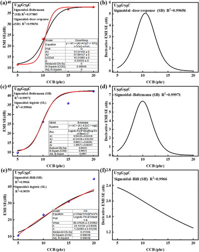
present the theoretical prediction models of EMI SE percolation thresholds of U30G70C, U50G50C, and U70G30C composites are SB, SD model, SB, SL model, and SH, SL model, respectively. It is found that all theoretical percolation predictions of EMI SE for UGC composites basically exhibit an S-shaped curve. Therefore, the optimal conductivity percolation thresholds of U30G70C, U50G50C, and U70G30C composites were determined to be 10, 15, and 15 phr, respectively. In , SB and SL models of U50G50C composites are essentially consistent. While the fitting results of SH and SL models of U70G30C composites are similar in . The EMI SE percolation thresholds for the U30G70C, U50G50C, and U70G30C composites are determined by ∼10.5, 10, and 3.3 phr, respectively. The theoretical predictions of these above Sigmoidal models are of great significance in the field of EMI shielding materials to determine the appropriate volume fraction of conductive fillers added to CPCs, especially when the filler addition is relatively high. Therefore, if the EMI SE percolation threshold of the composites is known, the problem of mechanical property deterioration and cost increase in the polymer matrix due to excessive filler content can be avoided.
Figure 9. Fitting the experimental and theoretical data based on SB, SD, and SH models, the derived curves show the variation of the EMI SE of the U30G70C, U50G50C, and U70G30C composites under different CCB additions. In which, (a,c,e) the relationship diagram between the EMI SE and CCB content of composites (b,d,f) derivative curves of EMI SE of U30G70C, U50G50C, and U70G30C composites with different CCB loadings.
According to the classic EMI SE percolation theory power law [Citation42]: SEtotal = SEtotal0(φ − φc)t, where ‘SEtotal0’ represents the EMI SE of the filler itself, ‘φ’ is the mass fraction of CCB, ‘φc’ is the percolation threshold of EMI SE, and ‘t’ is the dimension index, whose value depends on the dimension of the shielding network, and is used to describe how quickly the EMI SE value and the CCB content change. Plotting the EMI SE value vs. CCB content of the experimental test values yielded the estimated percolation threshold and dimensional index t of the EMI SE of the three composites. The linear fitting graph of the three composites’ EMI SE and CCB content is displayed in Figure S4. It was found that the squares of ‘R’ are 0.91691, 0.95767, and 0.999111, respectively, and the fitting results are ideal. Moreover, the EMI SE of U30G70C20, U50G50C20, and U70G30C20 composites increases with increasing CCB content. This is because the fact that composites with high CCB content increase the number of conductive paths and the density of conductive networks, which increases the resistance to electromagnetic waves, the dielectric and electric loss of the composites increase, thereby improving the EMI SE of the composites. In addition, the EMI SE of U30G70C20, U50G50C20, and U70G30C20 composites showed a linear function of CCB content. From the analysis of the linear fitting results, it can be seen that the t-value dimension coefficients of U30G70C20, U50G50C20, and U70G30C20 composites are 1.85, 2.15, and 2.19, respectively. It is inferred that the total EMI SE and CCB contents of these three composites conform to the power law.
3.5. Mechanical properties
The dispersion and distribution of carbon materials in composites may induce microscopic phase morphological changes that ultimately affect the mechanical and functional properties of polymer composites. Tensile fracture strength and elongation at break of the prepared GTR plates after grinding GTR powder three times with S3M technology are improved as compared with the un-mused GTR, while the tensile fracture strength of GTR increases from 3 to 7 MPa, and the elongation at break increases from 200 to 400% (see Figure S5(a)). show that the tensile fracture strength and elongation at break of UGC composites prepared by grinding GTR powder decrease significantly with increasing CCB content. For example, when the CCB content is 10 phr, the reduce arranges of tensile fracture strength of the three-element UGC composite is U70G30C10> U50G50C10 >30G70C10 compared with the two-element UG composite. However, the simultaneous introduction of UHMWPE and CCB still has a certain positive effect on the tensile strength of GTR for the tensile strength of pure GTR with low added valence. This approach will lay the groundwork for the future applications of physical recovery of GTR for recycling and preconditioning of high-added-value functional composites.
4. Conclusions
In summary, the various mass ratios (70/30, 50/50, 30/70 wt) of UG served as the matrix, conductive carbon black (CCB) acted as the filler, mechanical blending, and hot-press technology were built by a hybrid segregated structural electromagnetic shielding UGC composites. The relationship between electrical conductivity and EMI SE, the shielding mechanism of composites was revealed by employing a Sigmoidal/Growth mathematical model, and the changes between EMI SE and the electrical conductivity of the composites were predicted. The microstructure of the UGC composites showed that interconnect and hybrid conductive channels were successfully constructed, which are composed of CCB particles selected in the interfaces of UHMWPE-GTR compounds, and distributed in the GTR containing CB particles, resulting in the hybrid networks increasing the number of conductive networks and high conductive interfaces. When the CCB content sets to 20 phr, the conductivity of the U50G50C20 composite has a maximum value of 1.27 S/cm, which is 1.75 times that of U70G30C20 (0.75 S/cm), and 1.88 times that of U30G70C20 (0.68 S/cm). The prepared U30G70C20, U50G50C20, and U70G30C20 composites have good EMI SE, which are 37.5, 41.7, and 43.8 dB, respectively, this was mainly due to the continuous conductive channels and high-conductive performance between the micro-zonal interfaces. Therefore, UGC composite materials can block 99.99%of the microwave energy of the microwave energy. The shielding mechanism is mainly electrical loss. Moreover, the multi-interface scattering and polarization effects could induce interaction between electromagnetic waves (EMW), thereby facilitating the EMW absorption by the UGC composites. The relationship between EMI SE and electrical conductivity of UGC composite is consistent with the Sigmoidal model and is related to the CCB content. Different ratios of UGC composites can be obtained by controlling the blend ratios and optimizing the CCB content for electromagnetic shielding performance. This work will provide technical guidance for the future conversion of GTR into an applied flexible electromagnetic shielding composite.
Author contributions
Conceptualization, Q.Q. and C.W.; methodology, H.C.; validation, H.C., G.Z., and X.L.; formal analysis, H.C. and G.Z; investigation, H.C. and G.Z.; data curation, H.C. and G.Z; writing—original draft preparation, H.C.; writing—review and editing, Y.L.; visualization, G.L.; supervision, C.W.; project administration, Q.Q.; funding acquisition Q.Q. and C.W. All authors have read and agreed to the published version of the manuscript designed the project; wrote the manuscript.
Supplemental Material
Download MS Word (3.1 MB)Disclosure statement
No potential conflict of interest was reported by the authors.
Additional information
Funding
Notes on contributors
Huibin Cheng
Huibin Cheng, Fujian Provincial Key Laboratory of Advanced Technology, and Informatization in Civil Engineering, School of Civil Engineering, Fujian University of Technology, Fuzhou 350118, China. Research interests are polymer-based electromagnetic shielding composite material, polymer resource recycling and high-quality, water-based graphene electromagnetic shielding building coating.
Gongxi Zhang
Gongxi Zhang, Bachelor’s degree, College of Environment and Resources, Fujian Normal University, Fuzhou 350117, China. Research interests are resource recycling science and engineering, environmental engineering, eco-environmental economy and education.
Xuhong Liu
Xuhong Liu, Fujian Provincial Key Laboratory of Advanced Technology, and Informatization in Civil Engineering, School of Civil Engineering, Fujian University of Technology, Fuzhou 350118, China. Research interests are nickel-iron slag material, mechanical properties of components.
Yukai Lin
Yukai Lin, Master’s degree, College of Chemistry and Materials Science, Fujian Normal University, Fuzhou 350117, China. Research interests are medical hemostatic polymer material, plastic processing, natural polymer material, innovation and entrepreneurship development education, mindfulness intervention therapy.
Shenglan Ma
Shenglan Ma, Doctor’s degree, Fujian Provincial Key Laboratory of Advanced Technology, and Informatization in Civil Engineering, School of Civil Engineering, Fujian University of Technology, Fuzhou 350118, China. Research interests are material property monitoring and structural safety evaluation.
Guoliang Lin
Guoliang Lin, Doctor’s degree, Fujian Provincial Key Laboratory of Advanced Technology, and Informatization in Civil Engineering, School of Civil Engineering, Fujian University of Technology, Fuzhou 350118, China. Research interests are green building materials, new green materials.
Xiaoyi Zhang
Xiaoyi Zhang, Doctor’s degree, Fujian Provincial Key Laboratory of Advanced Technology, and Informatization in Civil Engineering, School of Civil Engineering, Fujian University of Technology, Fuzhou 350118, China. Research interests are new materials and functional design of civil engineering.
Baoquan Huang
Baoquan Huang, Bachelor’s degree, College of Environment and Resources, Engineering Research Center of Polymer Green Recycling of Ministry of Education, Fujian Normal University, Fuzhou 350117, China. Research interests are green recycling of nano-functional materials and polymer material.
Qingrong Qian
Qingrong Qian, Doctor’s degree, College of Environment and Resources, Engineering Research Center of Polymer Green Recycling of Ministry of Education, Fujian Normal University, Fuzhou 350117, China. Research interests are solid waste resource recycling and high-quality utilization, of polymer composite materials.
Chen Wu
Chen Wu, Doctor’s degree, Fujian Provincial Key Laboratory of Advanced Technology, and Informatization in Civil Engineering, School of Civil Engineering, Fujian University of Technology, Fuzhou 350118, China. Research interests are seismic design of engineering structure and functional structural material design.
References
- Liu C, Yu CY, Sang GL, et al. Ding, improvement in EMI shielding properties of silicone rubber/POE blends containing ILs modified with carbon black and MWCNTs. Appl Sci. 2019;9(9):1774. doi: 10.3390/app9091774.
- Chen W, Liu P, Liu Y, et al. Recent advances in two-dimensional Ti3C2Tx MXene for flame retardant polymer materials. Chem Eng J. 2022;446:137239. doi: 10.1016/j.cej.2022.137239.
- Formela K, Cysewska M, Korol J. Effect of compounding conditions on static and dynamic mechanical properties of high density polyethylene/ground tire rubber blends. Int Polym Process. 2014;29(2):272–279. doi: 10.3139/217.2849.
- Wang YH, Chen YK, Rodrigue D. Production of thermoplastic elastomers based on recycled PE and ground tire rubber: morphology, mechanical properties and effect of compatibilizer addition. Int Polym Process. 2018;33(4):525–534. doi: 10.3139/217.3544.
- Xie Y, Ye L, Chen W, et al. Electrically conductive and all-weather materials from waste cross-linked polyethylene cables for electromagnetic interference shielding. Ind Eng Chem Res. 2022;61(10):3610–3619. doi: 10.1021/acs.iecr.1c04813.
- Zhu J, Zhang X, Liang M, et al. Enhancement of processability and foamability of ground tire rubber powder and LDPE blends through solid state shear milling. J Polym Res. 2011;18(4):533–539. doi: 10.1007/s10965-010-9446-9.
- Simon-Stőger L, Varga C. PE-contaminated industrial waste ground tire rubber: how to transform a handicapped resource to a valuable one. Waste Manag. 2021;119:111–121. doi: 10.1016/j.wasman.2020.09.037.
- Aigbodion VS. Explicit microstructure and electrical conductivity of epoxy/carbon nanotube and green silver nanoparticle enhanced hybrid dielectric composites. Nanocomposites. 2021;7(1):35–43. doi: 10.1080/20550324.2020.1868690.
- Stern N, Dyamant I, Shemer E, et al. Hybrid effects in the fracture toughness of polyvinyl butyral-based nanocomposites. Nanocomposites. 2018;4(1):1–9. doi: 10.1080/20550324.2018.1447827.
- Cao S, Tao Y, Li H, et al. Multiscale hybrid CNT and CF reinforced PEEK composites with enhanced EMI properties. Nanocomposites. 2022;8(1):184–193. doi: 10.1080/20550324.2022.2100683.
- Duan L, Zhou Y, Deng H, et al. The influence of blend composition and filler on the microstructure, crystallization, and mechanical behavior of polymer blends with multilayered structures. Nanocomposites. 2018;4(4):178–189. doi: 10.1080/20550324.2018.1557432.
- JIa LC, Li YK, Yan DX. Flexible and efficient electromagnetic interference shielding materials from ground tire rubber. Carbon. 2017;121:267–273. doi: 10.1016/j.carbon.2017.05.100.
- Hu N, Masuda Z, Yan C, et al. The electrical properties of polymer nanocomposites with carbon nanotube fillers. Nanotechnology. 2008;19(21):215701. doi: 10.1088/0957-4484/19/21/215701.
- Cheng H, Cao C, Zhang Q, et al. Enhancement of electromagnetic interference shielding performance and wear resistance of the UHMWPE/PP blend by constructing a segregated hybrid conductive carbon black–polymer network. ACS Omega. 2021;6(23):15078–15088. doi: 10.1021/acsomega.1c01240.
- Matzui LY, Syvolozhskyi OA, Vovchenko LL, et al. Electrical and electromagnetic interference shielding properties of GNP-NiFe hybrid composite with segregate structure of conductive networks. J Appl Phys. 2022;131(5):055110.
- Deeraj BDS, Jayan JS, Raman A, et al. Polymeric blends and nanocomposites for high performance EMI shielding and microwave absorbing applications. Compos Interfaces. 2022;29(13):1505–1547. doi: 10.1080/09276440.2022.2068245.
- Sheng A, Yang YQ, Ren W, et al. Ground tire rubber composites with hybrid conductive network for efficiency electromagnetic shielding and low reflection. J Mater Sci Mater Electron. 2019;30(15):14669–14678.
- Rahaman M, Aldalbahi A, Govindasami P, et al. A new insight in determining the percolation threshold of electrical conductivity for extrinsically conducting polymer composites through different sigmoidal models. Polymers. 2017;9(10):527. doi: 10.3390/polym9100527.
- Rahaman M, Chaki TK, Khastgir D. Determination of percolation limits of conductivity, dielectric constant, and EMI SE for conducting polymer composites using sigmoidal Boltzmann model. Adv Sci Lett. 2012;10(1):115–117. doi: 10.1166/asl.2012.2138.
- Rahaman M, Al Ghufais IA, Periyasami G, et al. Recycling and reusing polyethylene waste as antistatic and electromagnetic interference shielding materials. Int J Polym Sci. 2020;2020:1–15. doi: 10.1155/2020/6421470.
- You W, Yu W. Onset reduction and stabilization of cocontinuous morphology in immiscible polymer blends by snowmanlike Janus nanoparticles. Langmuir. 2018;34(37):11092–11100. doi: 10.1021/acs.langmuir.8b02503.
- Chen J, Cui X, Sui K, et al. Balance the electrical properties and mechanical properties of carbon black filled immiscible polymer blends with a double percolation structure. Compos Sci Technol. 2017;140:99–105. doi: 10.1016/j.compscitech.2016.12.029.
- Thongruang W, Spontak RJ, Balik CM. Bridged double percolation in conductive polymer composites: an electrical conductivity, morphology and mechanical property study. Polymer. 2002;43(13):3717–3725. doi: 10.1016/S0032-3861(02)00180-5.
- Salzano de Luna M, Filippone G. Effects of nanoparticles on the morphology of immiscible polymer blends – challenges and opportunities. Eur Polym J. 2016;79:198–218. doi: 10.1016/j.eurpolymj.2016.02.023.
- Wu Z, Yang Z, Jin C, et al. Accurately engineering 2D/2D/0D heterojunction in hierarchical Ti3C2Tx MXene nanoarchitectures for electromagnetic wave absorption and shielding. ACS Appl Mater Interfaces. 2021;13(4):5866–5876. doi: 10.1021/acsami.0c21833.
- Zhou W, Chen Q, Sui X, et al. Enhanced thermal conductivity and dielectric properties of Al/β-SiCw/PVDF composites. Compos A Appl Sci Manuf. 2015;71:184–191. doi: 10.1016/j.compositesa.2015.01.024.
- Huang Y, Tan L, Zheng S, et al. Enhanced dielectric properties of polyamide 11/multi-walled carbon nanotubes composites. J Appl Polym Sci. 2015;132(40):42642. doi: 10.1002/app.42642.
- Hamidinejad M, Zhao B, Chu RKM, et al. Ultralight microcellular polymer-graphene nanoplatelet foams with enhanced dielectric performance. ACS Appl Mater Interfaces. 2018;10(23):19987–19998. doi: 10.1021/acsami.8b03777.
- Wang H, Xie H, Wang S, et al. Enhanced dielectric property and energy storage density of PVDF-HFP based dielectric composites by incorporation of silver nanoparticles-decorated exfoliated montmorillonite nanoplatelets. Compos A Appl Sci Manuf. 2018;108:62–68. doi: 10.1016/j.compositesa.2018.02.020.
- Yuan JK, Yao SH, Dang ZM, et al. Giant dielectric permittivity nanocomposites: realizing true potential of pristine carbon nanotubes in polyvinylidene fluoride matrix through an enhanced interfacial interaction. J Phys Chem C. 2011;115(13):5515–5521. doi: 10.1021/jp1117163.
- Saini P, Arora M, Gupta G, et al. High permittivity polyaniline-barium titanate nanocomposites with excellent electromagnetic interference shielding response. Nanoscale. 2013;5(10):4330–4336. doi: 10.1039/c3nr00634d.
- Wang H, Li SN, Liu MY, et al. Review on shielding mechanism and structural design of electromagnetic interference shielding composites. Macromol Mater Eng. 2021;306(6):2100032. doi: 10.1002/mame.202100032.
- Schelkunoff SA. The electromagnetic theory of coaxial transmission lines and cylindrical shields. Bell Syst Tech J. 1934;13(4):532–579. doi: 10.1002/j.1538-7305.1934.tb00679.x.
- Al-Saleh MH, Sundararaj U. Electromagnetic interference shielding mechanisms of CNT/polymer composites. Carbon. 2009;47(7):1738–1746. doi: 10.1016/j.carbon.2009.02.030.
- Zhang Y, Pan T, Yang ZJ. Flexible polyethylene terephthalate/polyaniline composite paper with bending durability and effective electromagnetic shielding performance. Chem Eng J. 2020;389:124433.
- Thomassin JM, Jerome C, Pardoen T, et al. Polymer/carbon based composites as electromagnetic interference (EMI) shielding materials. Mater Sci Eng R Rep. 2013;74(7):211–232. doi: 10.1016/j.mser.2013.06.001.
- Zhang WB, Wei LF, Ma ZL, et al. Advances in waterborne polymer/carbon material composites for electromagnetic interference shielding. Carbon. 2021;177:412–426. doi: 10.1016/j.carbon.2021.02.093.
- Al-Saleh MH. Influence of conductive network structure on the EMI shielding and electrical percolation of carbon nanotube/polymer nanocomposites. Synth Met. 2015;205:78–84. doi: 10.1016/j.synthmet.2015.03.032.
- Al-Saleh MH, Saadeh WH, Sundararaj U. EMI shielding effectiveness of carbon based nanostructured polymeric materials: a comparative study. Carbon. 2013;60:146–156. doi: 10.1016/j.carbon.2013.04.008.
- Rahaman M, Gupta P, Hossain M, et al. Predicting percolation threshold value of EMI SE for conducting polymer composite systems through different sigmoidal models. J Electron Mater. 2022;51(4):1788–1803. doi: 10.1007/s11664-022-09444-7.
- Taherian R. Experimental and analytical model for the electrical conductivity of polymer-based nanocomposites. Compos Sci Technol. 2016;123:17–31. doi: 10.1016/j.compscitech.2015.11.029.
- Shi YD, Li J, Tan YJ, et al. Percolation behavior of electromagnetic interference shielding in polymer/multi-walled carbon nanotube nanocomposites. Compos Sci Technol. 2019;170:70–76. doi: 10.1016/j.compscitech.2018.11.033.