
Abstract
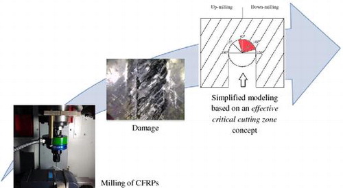
This article presents a simple framework for predicting the occurrence of delamination during milling of unidirectional carbon-fiber-reinforced plastics (CFRPs), based on a concept of effective critical cutting zone. To validate the concept, sets of milling experiments were conducted on unidirectional CFRP samples of varying fiber orientations and the delamination signature was measured through microscopic images. By observing the damage extent for different fiber orientation angles and different fiber cutting angles for up-milled and down-milled edges, and correlating them with different material removal mechanisms, it has been shown that the damage mainly depends on the portion of the fiber cutting angles that lie within the effective critical milling zone. Both the delamination and the normal cutting forces were found to be strongly dependent on the range of angles in this zone. In addition, it is shown that the cutting force may be used as a good approximation to determine the effect of machining/process parameters on the ensuing delamination damage during milling of CFRPs. For the tested samples, the normal cutting force decreased with an increase in the cutting speed and it increased with an increase in the feed rate of the cutting tool.
Introduction
The use of carbon-fiber-reinforced plastics (CFRPs) has grown considerably in recent years due to their superior properties such as light weight and high strength/stiffness. The widespread application of CFRPs in advanced industries such as aerospace and automotive, however, often requires assembling sub-structures with high-quality machined surfaces and adequate dimensional accuracies.Citation1–3 The mechanism of machining composite materials is different from that of conventional single-phased materials. Fiber-reinforced composites contain at least two different phases of materials with different mechanical properties (fiber and matrix), which makes them anisotropic in nature and causes defects during machining such as delamination, fiber pull out, etc. Hence, it is critical to understand and predict the mechanisms of material removal in composites for achieving desired quality of the machined surfaces.Citation4,5
A number of studies have been conducted in the past to understand the fiber failure mechanisms during milling of CFRP composites. Wang et al.Citation6 performed an experimental study on edge trimming of unidirectional composites with polycrystalline diamond tools. They found that the fiber orientation plays a significant role in the material removal process of fiber composites. Some other studies have been done on the machinability of carbon-epoxy composites and its effects on the flexural strengths of the specimens.Citation7–9 An effort was made to correlate the machining damage with the measured cutting forces during helical end milling of fiber-reinforced polymers by Kalla et al.Citation10 Mahdi and ZhangCitation11 used finite element modeling to study the damage mechanisms during machining of composites. In another study, Takeyama and IijimaCitation12 described the chip formation process in the machining of a glass-fiber-reinforced polymeric composite. Koplev et al.Citation13 studied the chip formation mechanism during material removal and correlated it with the material microstructure. The effect of cutting parameters and tool geometry on the sub surface damage in machined samples was investigated by Nayak and Bhatnagar.Citation14 In most of the earlier experimental studies above, flank wear phenomenon was clearly observed during milling composites. Hence, in order to explore the major contributors to the flank wear, Kim et al.Citation15 carried out orthogonal tool wear tests on several CFRP specimens. The tool wear was caused due to the very abrasive nature of the carbon fiber. It was shown that the feed rate most affected the surface roughness of the machined part, more than the effect of cutting speed. It was also reported that the optimum cutting conditions are highly dependent on the type of reinforcement as the mode of failure would differ from one composite to another. In general, continuous fiber reinforcements are stiffer than particulate or whisker reinforcements in fiber (principal) directions.Citation16,17
Among the past experimental and modeling studies on machining of CFRPs, not many have been devoted to find the exact nature of the “orientation-based” cutting mechanisms encountered during machining processes. The objective of the present work is to gain a better understanding and predictability of the orientation-based fiber failure mechanisms on the slot edges during CFRP milling. The ability to predict and monitor the damage in CFRPs during their machining would eventually allow for new design procedures to be adapted, specially to minimize the delamination defect in assembled parts. In the sections to follow, first the concept of the orientation-based cutting mechanisms will be reviewed (Section 2). Section 3 will present a simplified theoretical framework for identifying the effective critical cutting range (eccr) function for damage occurrence during UD composite milling. Section 4 will discuss the performed experiments on CFRP samples along with the data analysis to validate the proposed theoretical framework in Section 3. Finally, Section 4 outlines the main findings of the study.
Orientation-based cutting mechanisms
Due to the anisotropic nature of fiber-reinforced composites, distinctly different cutting mechanisms can be observed depending on the orientation of fibers with respect to the direction of tool motion. The fiber orientation angle ø is defined as the counter clockwise angle between the direction of feed motion and the direction of fiber reinforcement in the composite laminate. Figure exemplifies four different specimens that are aligned at different fiber orientation angles.
Figure 1 Specimens with different fiber orientation angles; a 0°; b 90°; c 45°; d 135°
On the other hand, fiber cutting angle θ is defined as the instantaneous angle between the cutting direction of a tooth on the tool and the direction of fiber alignment at the point of contact.Citation18 During milling of a specimen aligned at a particular fiber orientation, the cutting angle varies at different points of the cutting tool as shown in Figure for a specimen aligned at a fiber orientation angle of ø = 45°. It can be seen that the fiber cutting angle varies from θ = 45° at the up-milled edge, to θ = 135° at the top, and back to θ = 45° at the down-milled edge.
Figure 2 Cutting angles at different points of the cutting tool in a fiber-reinforced composite
Cutting mechanisms for different cutting angles
Different cutting mechanisms during machining of fiber-reinforced materials at two extreme cutting angles θ = 0° and θ = 90° have been summarized in Table .Citation19–21 Figures and also schematically show the fiber failure and material removal mechanisms when machining takes place at the cutting angles θ = 0° and θ = 90°, respectively. It has been reportedCitation22–24 that crushing and peeling are the dominated failure mechanisms for the aforementioned cutting angles. The material removal mechanisms for other cutting angles, for example θ = 45° and θ = 135°, are then a combination of both the crushing and the peeling mechanisms, as shown in Figures and , respectively. The material removal mechanisms for the cutting angles θ = 60° and θ = 150° are similar to those of θ = 45° and θ = 135° (Figure ).
Table 1 Differences between cutting mechanisms at cutting angles θ = 0° and θ = 90°
Figure 3 Material removal mechanism at cutting angle θ = 0° (adapted fromCitation19)
Figure 4 Material removal mechanism at cutting angle θ = 90° (adapted fromCitation19)
Figure 5 Material removal mechanism at cutting angle θ = 45° (adapted fromCitation19)
Figure 6 Material removal mechanism at cutting angle θ = 135° (adapted fromCitation19)
A simple framework for predicting the occurrence of damage
Critical and safe zones
The occurrence of composite damage depends upon fiber cutting angles and the mechanism under which the material is removed. As it was explained in Section 2, the material removal takes place mainly through two different mechanisms; by a peeling and subsequent bending mechanism for the cutting angle θ = 0° with minimum damage, and by a compressive crushing mechanism for the cutting angle θ = 90° with maximum damage. For all other fiber cutting angles that lie between θ = 0°–90° and θ = 90°–180°, the material removal mechanism is a combination of both peeling and crushing mechanisms.
It can be assumed that when fiber cutting angles lie between θ = 0°–45°, the peeling mechanism of material removal would be more prominent with minor crushing, whereas when fiber cutting angles lie between θ = 45°–90°, the crushing mechanism of material removal would become more significant with minor bending; in other words, the material removal mechanism switches from a peeling dominant to a crushing dominant mechanism at a fiber cutting angle θ = 45°. Since crushing-dominant material removal normally causes more damage, a significant fiber failure should be expected for a region where the material removal takes place between cutting angles θ = 45°–90°; while a region where the material removal takes place at cutting angles θ = 0°–45° would have less severe damage. Similarly, for cutting angles between θ = 90°–180°, the crushing-dominant material removal takes place for cutting angles θ = 90°–135° and peeling dominant material removal occurs between θ = 135°–180° and the transition between the two cutting mechanisms would occur at around θ = 135°.
From the orientation-based damage classification above, overall, it can be said that a critical cutting angle zone during milling of composites would lie between θ = 45°–135° angles for which significant damage may be expected since the material removal takes place by a crushing-dominant mechanism; while the safe cutting zone would lie between cutting angles θ = 0°–45° and θ = 135°–180° where the material removal is more peeling-dominant.
Defining an effective critical cutting range
During optimization of milling of UD composites, the main interest for a designer would lie in finding the extent of damage on the two edges of the milled slot. The machining conditions at regions closer to the slot edges would have the strongest influence on the extent of damage caused during machining. However, it is also possible that the delamination propagates in regions beyond the above critical zone (slot edges)Citation19–21 and hence the regions away from the edges would have some influence on the damage caused at the slot edges. For the purpose of quantification, the total machined region around the cutting tool is divided into four equal zones, two for the up- and two for the down-milled slots as shown in Figure .
Figure 7 Division of the total cutting region into four zones
Since zone I is closer to the slot edges, the cutting conditions in this zone would have a more significant influence on any damage occurring at the slot edges, as compared to the cutting conditions of zone II. Since different zones have different influences on the observed damage, a parameter named “effective critical cutting range” is defined here for each slot edge, milled in a specimen with a given fiber orientation:
(1)
And, the total effective critical cutting range for particular fiber orientation is defined as:
(2)
Where I is the portion of cutting angles in zone I that lies within the critical range, and II is the portion of cutting angles in zone II that lies within the critical range, for both up-milled, U, and down-milled, D, edges. Consider for example a case when machining is done on a sample with fiber orientation ø = 45° as shown in Figure a. In this case, both Zones I and II of the up-milled edge are completely occupied by the critical angles, that is I = 45° and II = 45°. On the other hand, for the down-milled edge it is seen that both Zone I and II do not contain any portions of the critical angles and hence I = 0° and II = 0°; therefore substituting these values in Eq. (2), the eccr is found to be 67.5° during slot milling of the specimen aligned at a fiber orientation angle of ø = 45°. Figure b–f also show the cutting angles at different machining locations along with the distribution of critical zone for specimens at other fiber orientations. The eccr can be similarly determined for each specimen orientation as summarized in Table . A high eccr value implies that the specimen is machined mostly at critical angles. Theoretically, the specimens with high eccr values are expected to have more damage, as will be evaluated experimentally in the next section.
Figure 8 Cutting angles and distribution of critical cutting zone (shown in red) for different fiber orientations a 45°; b 135°; c 0°; d 90°; e 60°; f 150°
Table 2 Theoretical determination of total eccr for specimens of different fiber orientations
Experimental validation
Milling tests (Figure ) were carried out on a 5 axis CNC machine EMCO concept MILL 250 to confirm the effect of the critical angles and effective critical cutting range (eccr) on UD CFRP damage by comparing the extent of delamination and observed normal cutting force values for each specimen orientation. Slots were milled on different specimens of varying fiber orientations from ø = 0° to ø = 150° using a 5 mm two flute slot end mill, made of high speed steel shown in Figure c. The length and thickness of CFRP specimens were 100 mm and 4 mm, respectively, and were fabricated using the hand lay-up process on 3 K Carbon Unidirectional Fabric 200 gsm received from “Hindoostan Technical fabrics limited” and impregnated with LY556 epoxy resin mixed with hardener HY951 in the ratio 10:1. For carrying out the machining tests, a spindle speed (vc) of 2000 rpm for cutting and a feed rate (f) of 40 mm/min were selected. In the experimental setup on the CNC machine, a Kistler rotating 4 component dynamometer RCD was attached with the spindle to measure the cutting forces. The dynamometer readings were transferred to a National Instruments data acquisition card and received on a computer using LabVIEW. The signals were received at a frequency of 20 Hz. The force values obtained were calibrated using the provided sensitivity chart. Experiments were repeated three times for each fiber orientation.
Figure 9 a CNC machine used for the CFRP experiments; b experimental arrangement; and c the high speed steel end machining tool employed for slot milling
The machining induced delamination was measured using a Dinolite digital microscope using 40× magnification in the direction perpendicular to the feed direction. The delamination factor was defined as the ratio between the width of maximum damage and the diameter of the tool used for machining:
(3)
Where Wmax is the width of maximum damage and W is the diameter of the tool. A schematic diagram for the measurement of Wmax and W is also shown in Figure .
Figure 10 Schematic of measurement of Wmax and W during slot-milling experiments on CFRP samples
Results and discussion
By making 5 mm slots on unidirectional CFRPs, it was found that the damage occurring on the slot edges clearly vary between specimens of different fiber orientations. This is theoretically due to the different distribution of cutting angles in the critical zones of each specimen at the given orientation. Table summarizes the delamination factors observed on the machined slots of different fiber orientations, with three test repeats (sets) for each.
Table 3 Measured delamination factors for different test specimens (note that eccr values are the same as those in Table )
Figure illustrates the variation in average delamination factor with changes in eccr for specimens with different fiber orientations. It can be seen that delamination increases with increase in eccr. Maximum damage is experienced when eccr = 90°, that is based on Table when machining is conducted on a specimen that is aligned at a fiber orientation of ø = 90° and minimum damage is seen when eccr = 45°, that is machining is done on a specimen aligned at a fiber orientation of ø = 0°.
Figure 11 Association of average delamination with changes in eccr range
Figure shows the variation of normal cutting force (Fx) with time when the slot was machined for specimen with a fiber orientation of ø = 0°. Here only the force values that lie within the box is considered for subsequent evaluations, so as to eliminate the unrelated force measurements during piercing and pull-out of the tool. Table summarizes the root mean square (RMS) normal force values measured during machining of all the specimens of different eccr, under the repeats of the tests. The maximum force is experienced when eccr = 90°, that is when machining is on a specimen aligned at a fiber orientation of ø = 90°. On the contrary, the minimum force is experienced when eccr = 45°, that is machining is on a specimen aligned at a fiber orientation of ø = 0°.
Figure 12 Sample variation of the average normal force with time (sec) as machining progresses; specimen fiber orientation case of 0°
Figure 13 Correlation between variation in average normal force and average delamination factor against eccr over a range of specimens with different fiber orientations
Table 4 Observed RMS normal forces for specimens with different eccr values for the three repetitions
Correlation between cutting force and delamination
By comparing the measured delamination factor values (Figure ) with the observed force values (Table ) for all specimens with different fiber orientations, it was seen that the trend in variation of both of the above process outcomes with change in eccr is similarly linear and increasing with eccr (Figure ).
Figure 14 Microscopic images of machining damage on upper-milled zone of specimens with fiber orientation of a ø = 45° and b ø = 135°
Occurrence of damage based on eccr
By inspecting the damage occurring for tested specimens of different fiber orientation angles on the up-milling and down-milling edges and correlating them with the material removal mechanisms described earlier, it was noticed that the delamination on both milled edges depend on the range of fiber cutting angles that lie within the critical cutting zone. Namely, the machined slot edges for which the fiber cutting angles lied within the critical zone had a high eccr value and significant damage was notable; whereas the slot edges for which the fiber cutting angles lied mainly within the safe zone held a low eccr value and remained mostly damage-free. To demonstrate these results and to correlate the damage with eccr, let us recall the example of the case for milling the specimen with fiber orientation angle of ø = 45° (see also Figure a). As explained earlier in Section 3.2, from the theoretical calculated eccr values for this specimen (Table ), it is expected that the critical angles are distributed completely on the up-milled slot with an eccr of 67.5° while the down-milled slot experiences machining only at safe cutting angles with an eccr of 0° and hence with no notable damage. In actual experiments, this theoretical prediction was clearly evident from the microscopic image of the corresponding specimen (Figure a).
As another check point, by comparing the theoretical material removal conditions between specimens of fiber orientations ø = 45° and ø = 135°, the up-milled and down-milled cutting conditions of these two specimens were expected to be opposite (mirror image) of each other as schematically was shown in Figure a and b. This prediction was substantiated from the microscopic images (compare Figure a and b and the inset images). The damage on the up-milled edge of the specimen with ø = 45° is almost the same as that on the down-milled edge of the specimen with ø = 135°. Similarly, both down-milled edge of the specimen with ø = 45° and up-milled edge of the specimen with ø = 135° had much less damage.
Effect of spindle speed and feed rate on milling force
Additional milling experiments were conducted to evaluate the effect of spindle speed and feed rate on the normal cutting force. It was earlier shown (Figure ) that force and delamination have a similar trend of variation with changes in eccr, thus the cutting force response may be used as a good approximate to determine the effect of machining parameters on damage (delamination) on the CFRP milled slots.
The experimental setup, materials, and machining procedures used for these set of tests were the same as those described in Section 4. Two different sets of new experiments were conducted, first by keeping the feed rate fixed and varying the spindle speed, and then by fixing the spindle speed and varying the feed rate (Table ). Figures and show the results of normal force during milling of these specimens with varying fiber orientations.
Table 5 Experimental matrices used for the two new set of experiments to study the effect of cutting parameters
Figure 15 Variation of normal cutting force with changes in eccr for different spindle speeds (spindle speed values indicated in the legend are those in Table )
Figure 16 Variation of normal cutting force with changes in eccr for different feed rates (feed rate values indicated in the legend are those in Table )
It is observed that both the spindle speed and feed rate influence the normal cutting forces significantly. For any given eccr value, the normal force decreases (Figure ) with an increase in the spindle speed for all fiber orientations. It has also been shown previously that with an increase in the cutting, the shear angle increases, leading to a smaller shear cutting plane.Citation25 The decrease in shear plane area decreases the shear forces required to produce the necessary stress to cause delamination. The friction coefficient also decreases at high spindle speeds, leading to a decrease in the normal cutting force. The RMS normal force values are observed (Figure ) to increase for all fiber orientations (or eccr values) with an increase in the feed rate. It had been previously shown that with an increase in the feed rate, the cross-sectional area of the uncut chip increases, leading to an increase in the normal cutting forces.Citation26 Another point worth noting from Figures and is that the effect of feed rate is more pronounced specially at higher eccr’s, when compared to the effect of spindle speed.
Concluding remarks
A simple and efficient framework was presented and validated for understanding and predicting the occurrence of delamination on slot edges during milling of unidirectional composites. It was seen that the damage occurring during the cutting process strongly depends on the local cutting angles at different locations of the tool. Both delamination and normal cutting forces were shown to be dependent on an effective critical cutting range (eccr), which is a function of multiple critical cutting angles (between θ = 45° and 135°) in both up-milled and down-milled zones of the specimen. The proposed theory could be potentially used in practice for avoiding the machining damage by milling the slots in directions that minimize the corresponding eccr value. It was also found that the cutting force may be used as a good approximation to determine the effect of machining parameters on the expected damage during machining of unidirectional CFRPs. Based on the experimental results obtained over a large range of eccr, for minimizing the cutting force, and hence the delamination factor, it would be desired to choose lower feed rates and higher spindle speeds.
While the presented theory as a first step was for UD composites and showed to be fairly accurate against the test data, in the next step it can be extended and tested for quasi-isotropic laminates. In the latter case, where a series of unidirectional laminas of different orientations are stacked symmetrically on both sides of the mid-plane, the total effective eccr would depend predominantly on the summation of individual eccr values of layers (i.e. where n is the number of layers that are exposed to the machining tool). It may also be worth extending and testing the theory for woven textile composites where at any particular point of machining at a given cutting plane, the tool would interact with fibers at multiple cutting angles, due to the interlaced architecture of weft and warp yarns.
References
- H. Hocheng, H. Y. Puwand Y. Huang: ‘Preliminary study on milling of unidirectional carbon fibre-reinforced plastics’, Compos. Manuf., 1993, 4, (2), 103–108.
- J. P. Davim and P. Reis: ‘Damage and dimensional precision on milling carbon fiber-reinforced plastics using design experiments’, J. Mater. Process. Technol., 2005, 160, 160–167.10.1016/j.jmatprotec.2004.06.003
- M. H. E. Hofy, S. L. Soo, D. Aspinwall, W. M. Sim, D. Pearson and P. Harden: ‘Factors affecting workpiece surface integrity in slotting of CFRP’, Procedia Eng., 2011, 19, 94–99.10.1016/j.proeng.2011.11.085
- H. Hosakawa, N. Hirose, T. Ueda and T. Furumoto: ‘High-quality machining of CFRP with high helix end mill’, CIRP Ann. – Manuf. Technol., 2014, 63, 89–92.10.1016/j.cirp.2014.03.084
- J. P. Davim, P. Reis and C. C. António: ‘A study on milling of glass fiber reinforced plastics manufactured by hand-lay up using statistical analysis (ANOVA)’, Compos. Struct., 2004, 64, 493–500.10.1016/j.compstruct.2003.09.054
- D. H. Wang, M. Ramulu and D. Arola: ‘Orthogonal cutting mechanisms of graphite/epoxy composite. Part 1: unidirectional laminate’, Int. J. Mach. Tools Manuf., 1995, 35, (12), 1623–1638.10.1016/0890-6955(95)00014-O
- K. Kim, D. Lee, Y. Kwak and S. Namgung: ‘Machinability of carbon fiber– epoxy composite materials in turning’, J. Mater. Process. Technol., 1992, 32, 553–570.10.1016/0924-0136(92)90253-O
- D. Arola and M. Ramula: ‘Machining-induced surface texture effects on the flexural properties of a graphite/epoxy laminate’, Composites, 1994, 25, (8), 822–834.10.1016/0010-4361(94)90143-0
- P. Sreejith, R. Krishnamurthy, K. Narayanasamy and S. Malhotra: ‘Studies on the machining of carbon/phenolic ablative composites’, J. Mater. Process. Technol., 1999, 88, 43–50.10.1016/S0924-0136(98)00377-X
- D. Kalla, J. Sheikh-Ahmad and J. Twomey: ‘Prediction of cutting forces in helical end milling fiber reinforced polymers’, Int. J. Mach. Tools Manuf., 2010, 50, 882–891.10.1016/j.ijmachtools.2010.06.005
- M. Mahdi and L. Zhang: ‘A finite element model for the orthogonal cutting of fiber-reinforced composite materials’, J. Mater. Process. Technol., 2001, 113, 373–377.10.1016/S0924-0136(01)00675-6
- H. Takeyama and N. Iijima: ‘Machinability of glassfiber reinforced plastics and application of ultrasonic machining’, Ann. CIRP, 1988, 37, 93–96.10.1016/S0007-8506(07)61593-5
- A. Koplev, A. Lystrup and T. Vorm: ‘The cutting process, chips and cutting forces in machining CFRP’, Composites, 1983, 14, (4), 371–376.10.1016/0010-4361(83)90157-X
- D. Nayak and N. Bhatnagar: ‘Machining studies of uni-directional glass fiber plastic (UD-GFRP) composites part 1: effect of geometrical and process parameters,’ Mach. Sci. Technol., 2005, 9, 481–501.10.1080/10910340500398167
- K. Kim, D. G., Lee, Y. K. Kwak and S. Namgung: ‘Machinability of carbon fiber-epoxy composite materials in turning,’ J. Mater. Process. Technol., 1992, 32, 553–570.10.1016/0924-0136(92)90253-O
- A. R. Hyde: ‘Ceramic matrix composites’, Mater. Des., 1990, 11, (1), 30–36.10.1016/0261-3069(90)90087-Z
- C. R. Dandekar and Y. C. Shin: ‘Modeling of machining of composite materials : A review’, Int. J. Mach. Tools Manuf., 2012, 57, 102–121.
- H. Wolfgang, D. Hartmann and C. Schütte: ‘Occurrence and propagation of delamination during the machining of carbon fibre reinforced plastics (CFRPs) – An experimental study’, Compos. Sci. Technol., 2011, 71, 1719–1726.
- D. H. Wang, M. Ramulu and D. Arola: ‘Orthogonal cutting mechanisms of graphite/epoxy composite. Part II: multi-directional laminate,’ Int. J. Mach. Tools Manuf., 1995, 35, (12), 1639–1648.10.1016/0890-6955(95)00015-P
- H. Y. Puw, H. Hocheng and H. C. Kuo: ‘Anisotropic chip formation models of cutting of FRP’, MED, 1995, 2, (1), 259–282.
- A. Koplev, A. Lystrup and T. Vorm: ‘The cutting process, chips, and cutting forces in machining CFRP’, Composites, 1983, 14, (4), 371–376.10.1016/0010-4361(83)90157-X
- M. Alauddin, M. A. Mazid, M. A. El Baradi and M. S. J. Hashmi: ‘Cutting forces in the end milling of Inconel 718’, J. Mater. Process. Technol., 1998, 77, 153–159.10.1016/S0924-0136(97)00412-3
- K. M. Patel and S. S., Joshi: ‘Mechanics of machining of face-milling operation performed using a self-propelled round insert milling cutter’, J. Mater. Process. Technol., 2006, 171, 68–76.10.1016/j.jmatprotec.2005.06.046