
 ?Mathematical formulae have been encoded as MathML and are displayed in this HTML version using MathJax in order to improve their display. Uncheck the box to turn MathJax off. This feature requires Javascript. Click on a formula to zoom.
Abstract
An extensive review of literature is conducted to present the evolution of the field of repair of thermoplastic composites (TPC’s) from when it was first mentioned in 1980. The TPC materials used today in aerospace structures are introduced along with the existing challenges to repair TPC structures. The three most promising fusion bonding techniques to address these challenges (i.e. induction, resistance, and ultrasonic welding) are explained. The certification authorities have extensive knowledge and data for repair of thermoset polymer matrix composite structures. However, such level of knowledge is highly limited for TPC structures. A lack of robust processes and the overall lack of data on TPC’s when compared to their thermoset counterparts are challenges that need to be addressed to implement TPC materials in aircraft structures.
GRAPHICAL ABSTRACT
1. Introduction
It is now well known that advanced composite materials are the material of choice in the aerospace industry due to their advantageous properties for both primary and secondary structures. In 2003, Boeing announced their plans to develop and build the first civil aviation aircraft, the Boeing 787 Dreamliner, featuring structures such as the fuselage, wings and tail, out of carbon fibre epoxy composites [Citation1]. The Dreamliner entered service in 2011, which was followed by the Airbus A350 in 2015, and the C-Series (now the Airbus A220) in 2016 with major usage of composites mostly in their primary structures [Citation1]. These aircraft are comprised of 50%, 53% and 20% composite material content by weight, respectively [Citation2, Citation3]. Other aircraft make increasing use of advanced composite materials in their structures, in particular thermoplastic composites (TPC’s). One example of these structures is the rudder and elevator of the Gulfstream G650 empennage which was possible due to substantial process advancement, and an extensive certification program with full-scale component tests [Citation4]. Other structures that utilize thermoplastic reinforced composites are the rudders of G500 and G600, the tail of the Augusta Westland AW169, and the wings’ leading edges on the Airbus A380 and Airbus A340–600 [Citation5, Citation6]. The latter was possible due to the advancement of fusion bonding techniques leading to TPC welding to create a unified structure. Studies have shown that the use of TPC’s represented 10% weight savings when compared to thermoset materials [Citation7–9]. [Citation6, Citation10–15] summarizes examples of aircraft structures manufactured with TPC’s.
Table 1. Aerospace structures which use TPC’s [Citation6, Citation10–15].
While thermoset polymer matrix carbon fibre composites are widespread in the industry, TPC’s are rapidly becoming increasingly popular due to their increased usage as observed in recent trends [Citation16]. Thermoplastic polymers can be melted, remelted, and reformed. In addition, TPC’s have short processing times, and they have the potential to be recycled and repaired, making them excellent sustainable materials [Citation17]. In addition, TPC’s have higher fracture toughness, better strength-to-weight ratios, and superior impact resistance and fatigue performance when compared to their metallic and thermoset composite counterparts [Citation17–19]. Therefore, designs can be optimized and the total number of plies can be reduced in TPC’s structures, further reducing the weight. Overall, these materials have superior environment resistance to moisture and solvents. TPC’s have also seen increased use in other sectors such as in the automotive industry [Citation20, Citation21] and in urban aerial mobility applications [Citation22, Citation23], where advanced processes to manufacture complex parts with high production rates are required. However, the main drawbacks when compared to thermoset polymer matrix materials are their high melt viscosities, high temperatures and pressures needed for consolidation, and higher cost [Citation24].
To fully take advantage of TPC’s on aircraft structures and to be able to certify them, it is key to develop a systematic methodology for repair. TPC’s which are assembled using fusion bonding techniques, are being used in very few structures (as presented in ). When these structures are damaged, they are often removed and replaced. However, supply of spare parts is often limited to very few suppliers around the world, which can lead to very long lead times and high replacement costs. While there are repair methodologies for thermoset matrix composite materials, the path for TPC’s is not yet clear. Viable repair techniques could potentially make the entire product life cycle more sustainable and less expensive as opposed to replacing these TPC parts. In thermoset polymer matrix composite structures, the cost of repair ranges from $15 000 USD to up to $150 000 USD per part. However, this only constitutes 8%–25% of the costs that it would represent replacing the part (without including shipping costs) [Citation25]. Furthermore, it would be possible to implement temporary solutions until a major repair is conducted in primary structures, thus returning the aircraft back to service in a short amount of time.
Fusion bonding involves joining two thermoplastic materials by heating the interface above the glass transition temperature (Tg) for amorphous or above melt temperature (Tm) for semi-crystalline polymers. Fusion bonding has been identified in different reviews and research articles as an alternative to mechanical fastening and adhesive bonding, and as a promising technique to join and repair TPC’s [Citation17, Citation26–32]. Different reviews [Citation32–34] have summarized different fusion bonding techniques and how these can be applied to repair thermoplastics. Xiao et al. [Citation33] identified the different damage types and proposed a fusion bonding technique for each damage. Vodicka [Citation34] summarized the same methods and provided limited mechanical performance data for each technique. Lastly, in 2020, Reis et al. [Citation32] focused on the three most promising fusion bonding techniques for repair (i.e. induction, resistance, and ultrasonic welding) along with the existing testing methods and Non-Destructive Inspection (NDI) to evaluate the quality of the welded joints, and numerical simulation. However, these reviews do not summarize the evolution of the field of TPC repair for aerospace from its roots and do not elaborate into how structures are currently repaired, the regulatory requirements, and the gaps that need to be fulfilled in order to certify the use of TPC structures.
The goal of this review is to discuss the origins and the evolution of TPC repair along with the current challenges and gaps impeding the implementation of TPC’s. A background is provided, including the use of thermoset and thermoplastic polymer matrix composite materials in aerospace structures. This background also includes classification, causes and detection of damage followed by how thermoset polymer matrix composite structures are repaired. Fusion bonding is then introduced, followed by a description of the three most promising techniques for repair: induction, resistance, and ultrasonic welding. Fusion bonding of dissimilar materials is also explained. Finally, the history and evolution of the field of TPC repair is presented, along with a summary and the perspectives moving forward, which show the existing challenges and the lack of a systematic methodology to perform repair on aerospace TPC’s structures.
2. Background
2.1. Materials in aerospace structures
Since the early 1920s, metals (in particular aluminum) were the material of choice for aerospace structures. Composite materials were used in military aircraft in the 60 s and 70 s in very modest percentages (i.e. 2% of the airframe of F15 and up to 27% on the AC-8B Harrier) [Citation35]. The use of thermoset polymer matrix composite materials have been increasing ever since (e.g. the Boeing 737, Airbus A350, and the C-series, now the Airbus A220), however aluminum is still being utilized.
Weight saving has been one of the main drivers to use advanced composite materials. Thermoset composites are comprised of fibres (i.e. carbon, glass, aramid, and boron) with a thermoset polymer matrix. Some of the most common thermoset polymer matrix materials used in aerospace are summarized in [Citation36].
Table 2. Common thermoset polymer matrix composites used in aerospace structures along with their thermal properties and processing temperatures.
Regulatory bodies such as the Federal Aviation Administration (FAA) and the European Union Aviation Safety Agency (EASA), original equipment manufacturers (OEM’s) such as Airbus and Boeing, and the engineers and technicians at the airlines have developed extensive procedures to repair metallic and thermoset polymer matrix composite structures. If the damage is on a load-bearing or critical structure, the repairs will be limited to bolted patches which may or may not include adhesive. A load bearing structure is defined for an element whose integrity is essential in maintaining the overall flight safety of the aircraft [Citation42]. Adhesively bonded repairs are limited in sizes so that if the patch fails, the repaired structure can still sustain the loads experienced in service (i.e. these patches are intended for cosmetic repairs only) [Citation42–44]. Repairs will be classified into Category A, B, or C, dependent upon the classification of the repair.
In the past decade, the use of TPC’s has been increasing due to their properties and environmental performance. Small parts such as brackets and clips were successfully processed using TPC in the past, and the trends indicate that these materials are of interest to be used in primary structures [Citation5–7]. TPC’s are comprised of fibres with a thermoplastic polymer matrix. Unlike thermoset resins, these do not have a rigid three-dimensional network structure. Instead, thermoplastic matrices have individual molecules that are held in place by Van der Waals, hydrogen, and weak secondary bonds [Citation24]. When heating these materials, the bonds holding these chains together break allowing the molecules in the polymer to move or flow with the application of pressure. Upon cooling, these molecules keep their new configuration and secondary bonds are restored. This unique characteristic allows thermoplastic matrices to be reheated, remelted and reshaped. Some of the most common TPC’s used in aerospace are outlined in , along with their molecular arrangement (i.e. amorphous or semi-crystalline), Tg, Tm, and processing temperatures. The polymer chains in amorphous materials arrange themselves in a random manner whereas in crystalline materials, the molecules are oriented in regular and repeating patterns [Citation45].
Table 3. Common TPC’s used in aerospace structures along with their thermal properties and processing temperatures.
3. Damage in composite aircraft structures
3.1. Damage causes and location
Damages can occur during manufacturing of composite parts which may include microcracks and delaminations, surface gouges and scratches, damaged holes and impact damage (e.g. caused by accidental dropped tools on the parts) [Citation51, Citation52]. These damages cannot always be prevented, so acceptable thresholds are incorporated in the design by demonstrating that ultimate strength can be attained with the damage present in the component. Some of these damages may go undetected or go beyond the specification limits thus they must be assumed to exist within a component with a damage tolerant design [Citation52].
During service, aircraft are periodically inspected as part of a maintenance schedule to look for possible damage. For instance, damage can be caused by impact (e.g. foreign object damage (FOD) such as runway debris, ground handling, dropped parts, aircraft-handling accidents, collisions with airport structures) and/or environmental factors (e.g. damage from snow and sand storms, lightning strike, bird strike, hail, ultraviolet (UV) radiation, rain erosion, moisture ingression) [Citation43, Citation53–55]. More than 80% of damages to composite structures have been attributed to impact, with the remainder being attributed to environmental factors [Citation53]. shows an example of a damaged aircraft structure due to environmental factors, in this case, lighting strike [Citation56].
Figure 1. Damaged aircraft composite structure due to lighting strike (reproduced with permission from J. Kim [Citation56]).
![Figure 1. Damaged aircraft composite structure due to lighting strike (reproduced with permission from J. Kim [Citation56]).](/cms/asset/4fa7cb47-9042-4d35-9091-ac69debb0227/yadm_a_2057137_f0001_c.jpg)
To identify the source and nature of damages, Dubinskiy et al. [Citation53] showed a review of approximately thirty thousand documents (i.e. operator’s reports, maintenance checks, and manufacturer databases) corresponding to 35 commercial aircraft with thermoset polymer matrix composite structures. In this report, dent damage was found to have the highest incidence rate of 56% with depths ranging from 0.1 mm to 50 mm, followed by skin deformation, scratches, holes, delamination, and cracks. The incidence of fibre pullouts, severe damage and others were found to be less than 1.5%.
These damages are often found in different sections of the aircraft structure. For instance, Airbus documented the location of damages encountered in service as summarized in [Citation57], revealing that 68% of the damages occur at the aircraft doors, while the remaining 32% were distributed amongst the standard fuselage sections, wings, nose, and the cone rear fuselage.
Figure 2. Distribution of damage in the aircraft structure (adapted from [Citation57]).
![Figure 2. Distribution of damage in the aircraft structure (adapted from [Citation57]).](/cms/asset/eeb6c5ea-302a-4d8d-93dc-e061d4e44f79/yadm_a_2057137_f0002_c.jpg)
Existing reports from the certifications authorities such as the FAA contain information limited to specific events, which are not classified by zone, type of damage, or material [Citation58].
3.2. Damage types
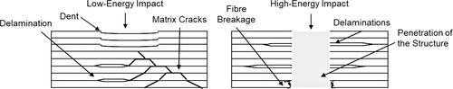
Ilcewicz et al. [Citation55] presented a classification of damage on thermoset polymer matrix carbon fibre composites that included delaminations and matrix cracks, caused by different impact energies. The morphology of these damages are influenced by impact energy and speed. For instance, high-energy impact at low speed can cause delaminations in larger areas without visible exterior damage. On the other hand, low-energy impact at high speed can penetrate the part without delaminations. Additional damages found in composite structures are caused due to environmental factors.
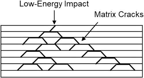
Matrix cracking () which can occur due to low and medium-energy impact, is typically located parallel to the fibres. These cracks do not tend to affect the residual strength and stiffness of the structure significantly. However, they can expose the material to the ingress of moisture and aviation fluids, causing degradation of the matrix-dominated properties such as interlaminar shear and compression strength [Citation52].
Figure 3. Matrix cracking due to low-energy impact.
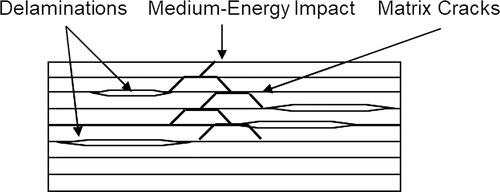
Delaminations () which occur along the interface of composite layers or along the bondline between two adhesively joined elements, reduce the stiffness and the structural integrity of bonded assemblies. Delaminations are often accompanied by matrix cracking which are caused by the mismatch of the properties of individual layers, ply drops, regions that experience out-of-plane bending, poor composite processing conditions, and low-speed and high-energy impacts [Citation59].
Figure 4. Diagram of delaminations occurring in a composite laminate after medium-energy impact.
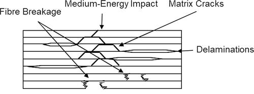
Fibre breakage () occurs due to medium-energy impact. High-energy impact over a large area may cause damage to internal structural elements beneath the surface, even when there is no visible damage. These may be accompanied by cracks which involve both fibre and matrix damage, and delaminations. These damages are typically caused by impact events, however, these may also occur due to the application of excessive local loads [Citation55]. Scratches tend to be of cosmetic nature, affecting only the outer layer of the resin without causing any further repercussions on the structural integrity of the part.
Figure 5. Fibre breakage due to medium and high-energy impact.
Dents (, left), which tend to occur due to impact, may be an indication of underlying damage (e.g. delaminations, matrix cracks, and fibre breakage). Punctures are caused by high-energy impact or due to the size of the impactor (i.e. when the impactor has a small diameter, it goes through the structure). High-speed, low-energy impacts can penetrate the area, causing further damage in the structures (, right).
Figure 6. Dents due to low energy impact (left), and penetration of the structure due to high-energy impact (right).
Other types of damage may occur due to erosion which may expose the surface fibres and lead to moisture ingress; heat damage may occur to the structures near the engines and other systems; and lighting strike which can degrade the protection system and cause damage to the skins. Exposure of the surface fibres, heat damage, degradation of the protection system of the aircraft, and skin damage may also be caused by FOD [Citation55].
3.3. Damage detection
Multiple methods of detection are used in order to find and assess damage on aircraft structures. These methods can be classified as NDI and destructive. NDI techniques are the most common, however, destructive inspection is used selectively when limitations are encountered with the former method in detecting damage [Citation52, Citation60]. The most common NDI technique is visual inspection. This technique is typically used to quantify dent depth, scratch length, the extent of the surface damage, resin starved and rich areas, wrinkles, ply bridging, and discoloration due to overheating. Internal flaws such as delaminations and disbonds cannot be detected with visual inspection. Once the damage has been found, the area of interest is selected for further evaluation. Tap testing using a coin or automated methods is a very common technique to detect delamination and disbonds. By tapping the inspection area and listening to the response, it is possible to determine if there is damage present in the component. For instance, a sharp sound indicates a well bonded structure, while a dull sound indicates an area with potential defects.
Ultrasonic inspection is used to determine internal delaminations, or voids that cannot be identified through visual inspection or tap testing. Radiography involves scanning a part or a component using x-rays while recording the absorption onto an x-ray sensitive film. The main challenge of this technique are the similar absorption characteristics of the fibres and the resin. This technique is useful to determine delaminations in corners, moisture ingression in honeycomb structures, voids in adhesive joints, and crushed and blown cores. Shearography induces stresses in a partial vacuum which causes defects such as delaminations and disbonds to expand, leading to surface deformation. These deformations are then detected before and during the test. Thermography involves methods where heat-sensing devices are used to measure variation in temperature in the inspected part. This method is useful in detecting moisture in honeycomb sandwich structures, thin laminates, and for surface defects.
On the other hand, destructive inspection involves resin characterization tests to evaluate the degree-of-cure of the resin, mechanical tests, acid digestion to evaluate fibre and void contents, microscopy which involves cross-sectioning the edge of the part and polishing. These methods provide relevant data, particularly during the development stages.
Lastly, inspection intervals are required and they differ depending on the aircraft and their operating environment. Some aircraft are inspected every 100 h of flight time, while others are inspected only once per year. Progressive inspections are conducted in order to minimize aircraft downtime. These are conducted following the Federal Aviation Regulations (FAR’s) [Citation61, Citation62].
3.4. Damage assessment
Size, type, location and detectability of the damage are combined to determine the risk and the threat that it represents to the structure. To date, there are few standards that outline the critical threats that must be identified in order to conduct a complete damage tolerance evaluation in composite structures [Citation42]. These standards indicate that when evaluating damage, it is required to gather the necessary data to develop the damage tolerance capability and ability to inspect for known threats. This data may include the function and location of the part in the aircraft, past service data, impact damage resistance, adjacent system interfaces and maintenance handling events. A known threat of particular concern is FOD and special attention should be given when gathering damage data from the field. After assessing the threat, the damage types are classified into five categories related to their increasing severity, which are labelled Category 1 to 5, as shown in [Citation42]. A description of each category is provided in the following paragraphs, as described in CMH-17, Volume 3, Chapter 3 [Citation52].
Figure 7. Diagram showing the different categories of damage with respect to the design load level and the increasing damage severity (adapted from [Citation42]).
![Figure 7. Diagram showing the different categories of damage with respect to the design load level and the increasing damage severity (adapted from [Citation42]).](/cms/asset/3c2f2400-7537-4d94-8fdd-7ec5ad736eb0/yadm_a_2057137_f0007_b.jpg)
Category 1 involves damages that may not be detected during a scheduled or directed field inspection, and includes barely-visible impact damage (BVID), minor environmental degradation, scratches, disbonds and porosity. This category is considered to be allowed manufacturing damage. The structures with Category 1 damage must be able to withstand ultimate design loads throughout the life of the aircraft.
Category 2 involves damages that can be detected reliably by the existing inspection methods at the prescribed maintenance intervals. Visible impact damage (VID) can include deep scratches, detectable delaminations or disbonds, and major local heat or environmental degradation. The structure with Category 2 damage must be able to withstand limit load capability until the damage can be found and repaired.
Category 3 involves obvious damages that require immediate repair and which can be detected reliably by operations or ramp maintenance staff who have not been trained in composite inspection within few flights of the damage occurrence. Large VID and damages which cause systems malfunctions, cabin noise, fuel leaks, or other obvious problems are included in this category. The structure with Category 3 damage must retain a specified load capability until damage is found and repaired. This load is often less or equal to limit load.
Category 4 involves damages which are obvious to the flight crew and that require repair after flight. Large bird strikes, lighting strike, landing gear tire burst or hail during flight are some examples. The structures with Category 4 damage must withstand a continued safe flight until landing.
Category 5 involves severe damages that cause grounding of flight events which were not anticipated and therefore, not considered in the design of the aircraft. For example, severe vehicle collisions, abnormally hard landings, and loss of aircraft parts in flight. The structures with Category 5 damage must not fly until the damage has been fully assessed and repaired.
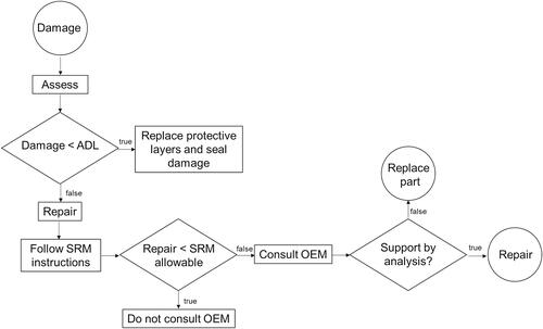
Once the damage has been fully identified, engineers determine whether it is within the allowable damage limit (ADL). In this case, maintenance will be performed to replace the protective layers. On the other hand, if the damage falls outside of the ADL, a repair must be conducted in accordance to the structural repair manuals (SRM) provided by OEM’s. The SRM includes procedures for damage clean-up, moisture removal, surface preparation, repair processing, and post-repair inspection. For the repairs that fall within the OEM’s SRM allowables, there is no requirement to consult the OEM further. However, in the case a major repair is required and it falls outside of the SRM, then the OEM must provide their input. Analysis and tests must be conducted to demonstrate that the proposed repair can restore the structure to an airworthy condition [Citation42, Citation63]. The process must produce repairs which result in a damage tolerant structure (i.e. the structure must be able to withstand its design loads for a period of time, without the damage reaching a critical size that could lead to the loss of the part) [Citation64]. The repair must be supported by analysis showing the residual strength requirements of the part can be attained, otherwise, the part is scraped and must be replaced [Citation65]. A flowchart of this process is shown in .
Figure 8. Flowchart of damage assessment and repair process.
4. Composite repair
4.1. Thermoset composite repair
Damaged structural aircraft components are generally repaired by using either an external doubler or an internal scarf patch. These repaired elements are affixed using mechanical fasteners, adhesives (i.e. bolted and bonded repairs, respectively), or a combination of the two. The selection of the repair method must satisfy a number of technical requirements such as structural integrity, lightning strike protection, radar signature, and aerodynamic performance [Citation66].
Bolted and bonded repairs start with the fabrication of patches prior to any repair operations. The repairs require damage tolerance capability evaluation and are classified into Category A, B, or C, as per the SRM’s. Category A involves a permanent repair where normal planned inspections are sufficient. Category B involves a permanent repair where supplemental inspections are required at specified thresholds and repeat intervals. Finally, a Category C involves a time-limited repair with planned supplemental inspections followed by replacement or reworking of the part within a specified time limit.
The repairs are often conducted at a repair facility or repair station except for those performed directly on the fuselage and the wing. The damaged part is most often removed from the aircraft and replaced with a temporary spare part to avoid grounding the aircraft. These repair facilities tend to have specialized equipment and trained personnel with knowledge and expertise on repair of composite structures. There is an interconnected network around the world which can allow servicing of aircraft from multiple airlines [Citation67].
4.1.1. Thermoset composite bolted repairs
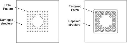
Bolted repairs on composites are performed in a similar manner as in metallic structures. Prior to conducting a bolted repair, the damage is removed by drilling a hole. The pattern is then laid out and pilot holes are drilled on the skin of the parent structure. The fastener holes are then drilled on both the patch and the skin, the patch is installed, and finally the repair is sealed using a sealing compound [Citation68]. Repairs conducted to primary structures must comply with the same damage tolerance requirements as for the original part. While this technique is reliable, adding numerous fasteners adds weight to the structure, creates stress concentrations around the fastener holes, and can create paths for galvanic corrosion. illustrates the hole pattern drilled on the damaged composite skin followed by a repair with a bolted patch. To date, bolted repairs are the only approved method for structural repair of load-bearing structures [Citation42–44].
Figure 9. Schematic of a bolted repair over a damaged composite structure showing the hole pattern (left) and the repaired structure with the fastened patch (right).
4.1.2. Thermoset composite bonded repair
Bonded repair, on the other hand, involves joining a composite patch to the parent composite structure using an adhesive. One of the main advantages of this process is the uniform load transfer without the added weight or the creation of stress concentrations [Citation52]. Bonded repair supposedly restores the composite structure’s original strength, maintaining the smooth aerodynamic contours if required. In addition, these types of repairs can also be applied on honeycomb structures. However, the limitations of this technique include the lack of redundancy in the load path (i.e. there are not multiple load paths in case of failure), the load limit is dependent upon the bonding process and the properties of the adhesive, and the lack of reliable NDI techniques to detect reliably the structural integrity of the bonded joint [Citation69, Citation70]. These repairs also require surface preparation which is a critical step in the process [Citation52, Citation55, Citation69–71]. Bonded repairs are currently limited in size and location for structures which can still operate at their limit load if the patch has fully failed and is no longer capable of carrying any load [Citation55].
4.1.2.1 Repair materials
Baker [Citation72] explained that composite repair materials can be either pre-cured (i.e. hard patch) or co-bonded with the adhesive (i.e. soft patch). The pre-cured composite can improve patch geometry to match the parent structure, and be used for high temperature advanced composites. The pre-cured patch repairs require expensive tooling, may have issues with dimensional stability and local warping, and typically involve long repair processing times. The co-bonded patch repairs are simpler to prepare, conform easily to the shape of the parent structure, and there is no need for specific tooling. However, the properties of the structure with the patch repair often do not match the properties of the parent structure, and they are prone to wrinkles, voids, and ply distortions. Overall, the co-bonded patch is often preferred due to the simplicity of the process and its applicability for in-situ repairs.
Co-bonded repairs can be classified into prepreg and wet lay-up repair. The former may utilize the same material as the parent structure or an equivalent which has been previously approved by the OEM. These patches are typically cured using an external heat source such as silicon heating blankets with a vacuum bag to apply pressure. Wet lay-up repairs utilize dry fabric with a two-part epoxy resin. Overall, wet lay-ups are the preferred repair approach of the airlines since the fabric can be formed to the shape of the parent structure, no external source of heat is needed to cure the material, vacuum pressure is sufficient to attain a high-quality bond and it does not require complex tooling [Citation73]. Other considerations that must be taken into account are that the repair material must also provide similar Tg and mechanical performance, and the material processing temperature must be below the Tg of the parent structure [Citation74].
4.1.2.2 Surface preparation and scarfing
Prior to any bonding operation, the first step is to remove any fluid residue from the surface of the damaged structure. Any paints, conductive and other coatings are also removed by sanding, grinding, or blasting an area larger than the intended repair (i.e. scarfing).
There are three main configurations of bonded repairs (i.e. scarfed, stepped, single and double lap joint). Scarfed and stepped repairs have reported high levels of strength recovery between 70-100% with minimum surface changes in the outer-mould lines [Citation66]. The scarfed repairs do not require grinding equipment to generate the stepped interface, and have less bondline stress concentrations than with the stepped pattern. Therefore, the scarfed repairs are preferred to restore load-carrying components. These are illustrated in .
Figure 10. Bonded repair configurations.
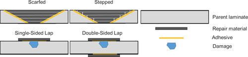
Scarf angles range from 3° to 7°, however, several studies have suggested that the optimum scarf angle is 3° (taper angle of 20:1) [Citation75–78]. In practice, structural load-bearing repairs often are up to 500 mm in diameter. For non-load bearing components, there is no size limit if using a co-bonded patch with wet lay-up and a room temperature cure in accordance with the SRM. The use of room temperature curing materials have some restrictions due to the required service temperatures of aircraft components (i.e. due to their Tg at a saturated condition), and their mechanical performance [Citation74, Citation79].
The last step is to grit blast or prepare the surface prior to conducting the repair. The purpose of this step is to remove the thin layer of low molecular weight species, and to roughen the repair surface, thus increasing the surface area and mechanical interlocking to improve adhesion [Citation80]. Certain materials may have low surface energies, which can be altered using chemical treatments, corona discharge, plasma and flame treatments, or ultraviolet radiation [Citation81–83].
When dealing with thick composite parts (i.e. thicker than 3 mm), Armstrong et al. [Citation79] stated that permanent bolted repairs are performed as this method prevents removing a large area to achieve the desired tapered scarf [Citation84].
4.2. Thermoplastic composite repair
As previously mentioned in the introduction, one of the advantages of TPC’s is their ability to be remelted and reformed, which gives the potential to repair these materials. Mechanical fastening, adhesive bonding and the three most promising fusion bonding techniques (i.e. induction, resistance and ultrasonic welding) have been proposed in the literature for this purpose [Citation17, Citation27, Citation32, Citation33, Citation85, Citation86]. Hot melt thermoplastic adhesives [Citation87, Citation88] or the insertion of an amorphous polymer have also been proposed [Citation26, Citation86, Citation89].
4.2.1. Mechanical fastening and adhesive bonded repairs
Mechanical fastening and adhesive bonding were first considered as obvious methods of repair for TPC’s [Citation33, Citation90]. Despite the reliability of mechanical fastening, this method adds weight to the TPC structure and can create stress concentrations, damaging the reinforcing fibres and promoting galvanic corrosion. On the other hand, adhesive bonding is a durable method, however, this joining method has been proven to be challenging with TPC’s due to the low surface free energy of thermoplastic polymers and their required surface treatments [Citation81–83, Citation91]. Existing surface treatments (i.e. plasma etching) which can increase the surface-free energy of TPC’s, require specialized equipment that would not be practical for repair. Seneviratne et al. [Citation71] recently published an evaluation of the effects of different surface preparation methods on TPC substrates, reiterating that the performance of adhesively bonded joints is extremely sensitive to the surface preparation technique. In addition, the same challenges encountered with bonded repair in thermoset polymer matrix composites remain in terms of certification of load-bearing structures, as explained previously in Section 4.1.2.
Stokes et al. [Citation19] reported an alternative method for repair by using a hand solvent method in which the interface of the TPC substrates to be joined are softened by the use of a solvent. These parts are then kept under pressure while the polymer chains diffuse across the interface. Once the solvent has evaporated, a joint is achieved. In certain instances, a thermoplastic containing the solvent can be used, allowing to fill regions of mismatched surfaces. While this technique can be utilized in some applications, it is a slow process, it is not suitable for large-scale repair operations, and it may not reproduce consistent results.
4.3. Fusion bonding techniques
Fusion bonding was primarily introduced as a method to join TPC structures by heating the interface above Tg for amorphous or above Tm for semi-crystalline polymers. By increasing the temperature, it is possible to reduce the viscosity to allow the movement of the polymeric chains to move across the welding interface. By applying pressure, close contact between adjacent substrates is created (process also referred to as intimate contact). After intimate contact has been created, inter-diffusion of the polymer chains follows, attaining a full weld [Citation92–98]. The interlaminar bond strength, is a function of the processing temperature, the consolidation pressure and the processing time. This process is illustrated in [Citation94, Citation99].
Figure 11. Stages of the fusion bonding process (adapted from [Citation94]).
![Figure 11. Stages of the fusion bonding process (adapted from [Citation94]).](/cms/asset/4b0f7fef-408b-44a0-963e-69619ade8166/yadm_a_2057137_f0011_c.jpg)
Wedgewood et al. [Citation100] demonstrated that the quality of these welds was similar to that of autoclave or compression moulded parts. One of the main advantages of fusion bonding is that the substrates to be joined do not require any surface preparation [Citation71]. Despite their advantages, joining and assembly of TPC’s is less mature when compared to their thermoset counterparts due to the overall lack of historical data available. This limitation currently inhibits its wide adoption, including repair.
Yousefpour et al. [Citation17], reported a variety of thermoplastic joining techniques, which are classified on how heat is generated, specifically into thermal, friction and electromagnetic welding. Induction and resistance are categorized as electromagnetic welding techniques, whereas ultrasonic is categorized as a friction welding method. Electromagnetic welding relies on a heating element (e.g. carbon fibre, stainless mesh, or magnetic particles) located at the interface between the adherends where heat is generated by either Joule heating, induced eddy currents, or hysteresis losses. The polymer chains then begin to diffuse under the application of pressure. On the other hand, in friction welding, heat is generated at the interface by friction under the simultaneous application of pressure. The material is subsequently cooled and consolidated. The fundamental of fusion bonding is highly favourable to be used for repair processes of TPC’s since repair involves joining of a patch to a prepared surface.
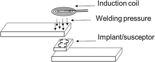
4.3.1. Induction welding
Induction welding consists of passing an alternating voltage through a conductive coil to induce a variable magnetic field with frequencies in the range of 200–500 kHz [Citation17, Citation19, Citation101]. Electrically conductive susceptors or implants (i.e. a material which heats faster than the laminate) are placed at the interface of the substrates to be welded. The susceptors or implants consist of carbon fibre layers, a metallic mesh, or magnetic particles [Citation102–105]. When the induction coil is placed in the vicinity of these implants, eddy currents are induced, matching the frequency of the magnetic field [Citation34, Citation106, Citation107]. These eddy currents generate heat when energy is lost due to the resistance of the material via the Joule effect, as per EquationEquation 1(1)
(1) , where
is the frequency;
is the relative magnetic permeability of the material;
is the applied magnetic field amplitude as a function of the current
is the surface area of the susceptor; and
is its electrical resistance [Citation102].
(1)
(1)
A second heating mechanism consists of heat dissipation through hysteresis losses within magnetic materials. When subjected to an alternating magnetic field, the magnetic domains of the material experience alternating magnetization where a fraction of the electromagnetic energy is absorbed and released as heat into the surrounding thermoplastic. The heating rate decreases as the Curie temperature of the magnetic material is approached (i.e. the temperature at which the material becomes non-ferromagnetic). EquationEquation 2(2)
(2) describes this heating mechanism through hysteresis losses, where
is the dissipated power per unit volume,
is the frequency,
is the magnetic permeability of vacuum,
is the applied magnetic field, and
is the magnetization of the material [Citation108, Citation109].
(2)
(2)
Pressure is applied during or after heating until the polymer solidifies, thus welding the adherends [Citation17, Citation101, Citation110–112]. shows a schematic of an induction welding setup with a lap shear joint configuration.
Figure 12. Schematic of induction welding setup with a lap shear joint configuration.
Villegas et al. [Citation110] reported the optimum range of pressure to be between 0.2 MPa and 1.2 MPa with times ranging from ten seconds to up to six minutes. Appropriate consolidation pressure is needed to ensure the required intimate contact between the two substrates. Ahmed et al. [Citation101] mentioned that inadequate pressure can generate defects such as voids, cracks, and folds. The use of vacuum bag pressure has been reported in literature in a very limited manner in the induction welding process [Citation101, Citation111]. For instance, Rahim et al. [Citation111] used an induction welding setup to monitor the temperature within the welding zone in real-time using high definition fibre optic sensing. The processing time was reduced by approximately 50%, however no quantitative data was found showing high mechanical performance of thermoplastic substrates using induction heating at low consolidation pressures (i.e. vacuum bag only).
One of the main advantages of induction welding is the ability to join two conductive materials such as carbon fibre without any additional susceptors or implants [Citation103–105]. However, if the adherends are not electrically-conductive or susceptible to a magnetic field, it is possible to use a susceptor layer which can consist of a metallic mesh or magnetic particles in the form of a powder. In addition, continuous induction welding with complex and large geometries is possible by moving the induction coil along the structure [Citation113]. A damaged structure or weld can be reopened by induction reheating when using electrically conductive susceptors. This possibility would represent an advantage for repair applications. Although there has been mention in the literature about portable induction welding units [Citation34], a challenge remains in the size of the power supply units. The disadvantages of this process are the non-uniform heat distribution and targeting the heat at the desired interface, the difficulty of welding large and thick parts, and the need to have fibres laid up at two different angle orientations (i.e. susceptors or implants would be required when joining unidirectional laminates) [Citation17].
In terms of modelling, numerical simulation of induction welding was at first focused on understanding the predominant heat generation mechanism in the material, where both Joule heating within the fibres and heating at the fibre junctions were studied [Citation103, Citation105, Citation114–117]. Different models have since been developed with the ability to predict the temperature on both fabric [Citation103, Citation118, Citation119] and unidirectional laminates [Citation120]. Yarlagadda et al. [Citation104] developed a unified model to determine the dominating heat generation mechanisms regardless of the composite system being welded (i.e. to take into account for different fabric, resin and laminate configurations). The results of this simulation showed that junction heating dominates carbon fibre composite systems however the fibre architecture (i.e. fabric vs. unidirectional material) has a significant influence in determining the dominant mechanism [Citation104]. Gouin O’Shaughnessey et al. [Citation121] developed a three-dimensional (3 D) finite element (FE) model to predict the heating of two unidirectional carbon fibre TPC adherends which included the experimental setup, taking into consideration the electrical conductivity and heat capacity of the material. In this work, the authors compared induction with resistance and ultrasonic welding, highlighting the different heat patterns at the welding interface and concluding that the mechanical performance was not affected. With the increased use of continuous welding processes, numerical simulation has the potential to be used for optimization of the welding processes. Lionetto et al. [Citation113] developed a two-dimensional (2 D) FE model which was able to predict the temperature distribution at the welding zone as a function of the coil speed and current, the melting behaviour, and the crystallinity which was developed at the interface during continuous induction welding.
In terms of application, induction welding has already been used to assemble TPC aerospace structures. These structures include the rudder from the Gulfstream G650 and the elevator of the Dassault Falcon 5X, both made out of carbon fibre fabric and PPS, and the carbon fibre PEKK unidirectional tape stringers to skin for the STELIA demonstration fuselage [Citation8, Citation122]. Recent research on repair has been published with induction heating, where promising results were obtained when evaluating the structural integrity of the repairs [Citation123, Citation124].
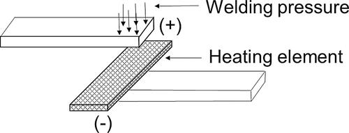
4.3.2. Resistance welding
In resistance welding, electric current is passed through a resistive or heating element. Heat is generated as per the Joule effect, as shown in EquationEquation 3(3)
(3) , where
is the resistance of the heating element and
is the applied current [Citation28].
(3)
(3)
This heat softens the matrix or melts the interface in the case of amorphous or semi-crystalline materials, respectively. The heating element can be a layer of carbon fibre (which can be made out of carbon fibre prepreg, fabric or unidirectional material) or metallic such as stainless steel. Pressure is applied until the polymer solidifies. shows a schematic of a resistance welding setup.
Figure 13. Schematic of resistance welding setup.
Ageorges et al. [Citation125] reported consolidation pressures between 0.1 and 1.2 MPa with carbon fibre PEI laminates, where at 0.1 MPa, a positive change in thickness was observed at the interface region of the welded substrates. This thickness change indicated de-consolidation during the welding process. Doubling the pressure reduced this phenomenon. In the same work, consolidation pressures of 0.4–0.8 MPa yielded optimum single lap shear values above 24 MPa with welding times of 90 s. Establishing processing windows would allow to potentially reopen a defective weld or joint to be then reprocessed. Brassard et al. [Citation126] explored other avenues such as adding multi-walled carbon nanotubes (MWCNT) in the heating element by using amorphous PEI, which would allow to heat the interface above the Tg of the material but well below Tm of crystalline materials such as PEEK.
The advantages of this technique are that the heat is generated only at the weld interface, the ability to weld thick laminates and the possibility to adapt this technology to large and long welds through a continuous resistance welding (CRW) process to assemble or repair structures directly on the aircraft [Citation127, Citation128]. In addition, very little or no surface treatment is required to conduct the weld while attaining high bond strengths [Citation71, Citation110, Citation129, Citation130]. Ageorges et al. [Citation131] and Stavrov et al. [Citation132] highlighted a main advantage of carbon fibre elements which is the high compatibility with the adherends, leading to high mechanical performance. Yousefpour et al. [Citation129] demonstrated that the stainless steel mesh produced higher single-lap shear strengths when compared to carbon fibre elements, with values of up to 50.1 MPa using PEEK and PEI adherends with both carbon fibre and fibre glass. However, the main drawback of metal mesh is that this dissimilar material remains at the interface, and the added weight to the structure [Citation17, Citation132].
On the other hand, one main challenge of resistance welding is current leakage that can lead to long welding times, non-uniform heating and inconsistent welds. This issue has been resolved by using glass fibre electrical insulation between the heating element and the laminates [Citation17, Citation19, Citation131] or coating the heating element with TiO2 [Citation133]. Another challenge in resistance welding is the need for a direct electrical connection between the power supply and the heating element. These connectors are typically made out of copper which are pressed against the heating element at a defined clamping pressure. If the heating element is made out of carbon fibre, the matrix needs to be burned away from the ends to connect to the copper blocks, which may damage the material. Clamping pressure also can affect the resistance. Clamping pressures between 4 and 20 MPa have been reported to achieve a repeatable process [Citation17, Citation95, Citation134]. Finally, the challenge of being able to attain high enough pressures to ensure consolidation of the joint in a repair scenario remains.
In terms of simulation, numerical modelling for resistance welding was first developed in the 1990s, where the energy equation was applied to predict the temperature distribution of the welded substrates [Citation95, Citation135–137]. Models for both autohesion (i.e. diffusion of polymer chains across surfaces) and intimate contact were incorporated using FE modelling. The effect of insulation and temperature profiles were simulated using ANSYS [Citation95, Citation136]. Talbot et al. [Citation138] developed 2 D and 3 D models using FE which were used to investigate the effects of clamping distance on local edge overheating and the influence of heat conduction along the laminates, respectively. The clamping distance (i.e. the distance between the edge of the weld and the copper electrical connector) was found to have an influence on overheating. In addition, the 3 D model showed large temperature gradients along the length of the laminates (i.e. the z-direction) due to the thermal conductivity along the length of the laminates. These gradients resulted in degradation, and a combination of weld and no weld zones at the interface. Other researchers are now focusing on modelling of the continuous thermoplastic resistance welding process incorporating the heat transfer physics and the electrostatic effects of the setup using COMSOL Multiphysics® [Citation128, Citation139, Citation140].
In terms of application, an Airbus A320 bulkhead demonstrator which consists of eight press-formed carbon fibre fabric layers with PPS segments was assembled using resistance welding. The J-nose leading edge of the Airbus A340–500/600 and Airbus A380 aircraft which are made out of glass fibre and PPS were also assembled using this technique [Citation134].
A practical demonstration of repair was performed by the Northrop Corporation using resistance heating with amorphous polymer bonding, more specifically with the Thermabond™ process [Citation141]. This process consisted on co-consolidating an amorphous resin layer of PEI onto a patch made out of APC-2 PEEK in an autoclave with 0.2 MPa of pressure at 385 °C for 30 min. The surface of the PEEK parent structure, however, needed to be etched and primed as it was not possible to co-consolidate a layer of PEI onto it. The repair patch was then joined to the structure at 150–165 °C for 60 min (for moisture bake-out) and then between 285 and 330 °C for 30 min. By using an amorphous polymer layer, it was possible to perform the repair above the glass Tg of PEI but below the melting temperature Tm of the parent PEEK structure. The repair was inspected using NDT and subjected to 115% of the design ultimate load where the repair patch was not affected.
4.3.3. Ultrasonic welding
In ultrasonic welding, two substrates are kept in contact under pressure which are then subjected to a high-frequency vertical oscillation generated by a piezoelectric converter, ranging from 20 to 40 kHz [Citation17, Citation28] at low amplitudes ranging from 10 to 250 µm [Citation142]. Heat is then generated by a combination of viscoelastic heating and surface friction. The viscoelastic heating rate, which is the predominant heating mechanism at temperatures higher than the Tg of the material, can be defined as per EquationEquation 4(4)
(4) [Citation143], where
is the frequency of the vibration,
is the elastic modulus of the adherend, and
is the cyclic strain imposed on the material which is linked to the amplitude of the vibration.
(4)
(4)
A schematic of an ultrasonic welding setup is shown in .
Figure 14. Schematic of an ultrasonic welding setup.
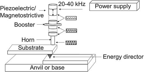
Heat is prone to concentrate around asperities as these tend to dissipate heat. Asperities or energy directors are resin-rich features used to concentrate the generation of heat at the welding interface. These asperities which are typically shaped as triangular protrusions can be designed and pre-moulded onto the part to target heat at the joint interface [Citation144–146]. It is also possible to use flat neat polymer films at the interface instead of energy directors [Citation145–148]. As the melting temperature is reached, the energy directors begin to flow under the application of pressure allowing the diffusion of the polymer chains across the interface.
The most important process parameters are the welding force, the vibration amplitude and the time. The welding force and the vibration amplitude determine the heating rate which is generated during the process while the vibration time determines the amount of energy used during the process to create a welded joint, which is ultimately related to bond quality. Viscoelastic heating is defined by EquationEquation 4(4)
(4) , whereas surface friction is defined as per EquationEquation 5
(5)
(5) [Citation142]. This equation relates the stresses normal to the welding interface,
(which is composed of a static and dynamic component,
and
) to the static welding force,
the area to be welded,
and the dynamic normal stress generated by the vibration,
(5)
(5)
Semi-crystalline TPC’s such as PEEK, PEKK, and PPS are more challenging to weld ultrasonically than amorphous materials as these tend to absorb energy. More heat is required to melt the crystalline phase, leading to higher frictional amplitudes [Citation149]. Ultrasonic welding has been investigated by varying the distance from the horn to the joint in the near field (i.e. less than 6 mm), and far field (i.e. more than 6 mm). Benatar et al. [Citation150, Citation151] showed that it was possible to weld both amorphous and semi-crystalline thermoplastic polymers in the near field. However, the semi-crystalline materials yielded poor welding performance in the far field. In terms of consolidation pressures, Villegas et al. [Citation110] reported up to 3 MPa required for this process.
One of the main advantages of this method is its speed when compared to other fusion bonding techniques as it takes just few seconds to complete the process. With the energy directors, there is no need to add any heating elements or susceptors as it is the case with resistance and in some cases, with induction welding, respectively. Welding without any energy directors is also possible, however, controlling the location of the interface and the risk of overheating becomes a challenge. Li et al. [Citation152] demonstrated a solution to this challenge by designing the ratio between the contact surfaces of the anvil and the adherend, and the sonotrode and the adherend, respectively. Tutunjian et al. [Citation153], used a hollow clamp around the sonotrode, overcoming the overheating issue. Another significant advantage of this welding process is non-invasive in-situ process monitoring. Benatar et al. [Citation143] first established the relationship between the quality of the welded joint and the welding process parameters such as the impedance of the interface, the dissipated power and the acceleration of the fixture. These parameters were measured by using a wattmeter and by mounting an accelerometer to the fixture, leading the path to in-situ monitoring of the process. Villegas et al. [Citation154, Citation155] used a welder controlled with a microprocessor where the dissipated power and the displacement of the sonotrode were recorded. A relationship between these two parameters provided an indication of the quality of the welded joint. Furthermore, no additional surface preparation is required. One of the main drawbacks of this technology is the limitation of the vibration to penetrate thicker parts, especially in semi-crystalline materials due to the absorption of these high frequency vibrations. In addition, due to the transmission of mechanical vibration required to heat the interface, there may be excessive noise generation and the welded substrates may be more susceptible to fatigue [Citation156].
In terms of simulation, in the late 80 s, Benatar et al. [Citation150, Citation151] developed a simplified model on high frequency ultrasonic wave propagation and attenuation in viscoelastic materials. Moduli values were used in a lumped parameter model, predicting the heating rates and energy dissipation. In this work, the relationship between impedance of the interface, dissipated power and acceleration was established. Suresh et al. [Citation157] developed a model to evaluate temperature distribution for different joint designs using ANSYS and to understand the distribution of the heat affected zone (HAZ) in the weld. Viscoelastic heating was found to depend on the frequency, square of amplitude and loss modulus. Using COMSOL Multiphysics®, Levy et al. [Citation145] found that interfacial friction is the predominant heating mechanism in ultrasonic welding while viscoelastic dissipation was predominant only at higher temperatures. Palardy et al. [Citation158] modelled the periodic loss of contact between the sonotrode and the adherends (i.e. hammering effect), showing that this effect decreases as the weld temperature increases. In 2020, an article on continuous ultrasonic welding was published by Jongbloed et al. [Citation159], however there were no numerical simulations performed.
In terms of application, ultrasonic welding was used in the Clean Sky EcoDesign demonstrator to assemble carbon fibre PEEK hinges and carbon fibre PEKK clips to carbon fibre PEEK C-frames. Frederick et al. [Citation160] studied the potential of using ultrasonic welding along with resistance heating and MWCNT’s to reopen a weld for repair. The HAZ travelled to the adherends in the through-thickness direction, concluding that the use of these particles in combination with ultrasonic welding was not apt for repair. Villegas [Citation142] stated that this technology is still not considered to be mature enough, which hinders its application for welding of long parts. Ultrasonic welding has been considered to be a promising technique for repair [Citation34, Citation161]. However, more research is needed on the subject to fully expand the application of this method.
4.4. Fusion bonding of dissimilar materials
In general, to bond or join metal and thermoset polymer matrix composites, the surface of the adherends needs to be prepared. However, joining TPC’s with thermoset matrix adhesives is challenging due to the low surface free energy of the thermoplastic resins and due to its chemical incompatibilities [Citation81–83, Citation91], making fusion bonding an alternative to adhesive bonding for these materials. Thermoplastic composite materials do not need the extensive surface preparation as in metals and thermoset polymer matrix composites.
Fusion bonding can be used to join metals, thermoset and thermoplastic polymer matrix composites by using either a thermoplastic hybrid interlayer or by co-curing a thermoplastic film to the adherend. Don et al. [Citation162] and Jacaruso et al. [Citation163] proposed a thermoplastic polymer layer which was processed with a woven roving fibre cloth during a prepregging operation. One side of the cloth was kept dry. The hybrid layer was then incorporated during wet lay-up of a thermoset matrix laminate. This method did not require the polymers to be compatible. McIntire et al. [Citation164] used a similar hybrid thermoplastic and fibre cloth layer to join a metal fitting to a thermoset polymer matrix composite shaft using resistance heating while Ageorges et al. [Citation165] used this method to join carbon fibre substrates with an epoxy matrix and PEI. In the second method (i.e. co-curing a thermoplastic film to the adherend), a chemically compatible thermoplastic layer is co-cured with a thermoset polymer matrix composite [Citation162]. The strength of the bond is dependent upon the inter-diffusion of the polymeric chains of both materials. To perform the joining operation, a third polymer is used which is compatible with both the thermoset and thermoplastic matrices, creating an interpenetrating network (IPN) with the thermoset adherends [Citation166–169]. Only a limited number of thermoplastics are compatible with thermoset polymer matrix polymers such as amorphous PEI, polysulfone (PSU) and polyethersulfone (PES). These materials tend to be miscible with the uncured thermoset resins and interact with the epoxy matrices providing strong interfacial bonding. Semi-crystalline polyamide (PA) is reported to be a thermoplastic candidate to be used as an intermediate layer between the substrates if they can form an IPN with the epoxy [Citation170, Citation171]. Overall, the main challenge with this technique is the thermal degradation of the thermoset polymer due to the high processing temperatures of the thermoplastic material.
Fusion bonding combined with hot melt thermoplastic adhesives or an amorphous layer such as PEI can be used to join amorphous and semi-crystalline thermoplastic materials. The advantages of this method include the infinite shelf life of TPC’s, it is a rapid bonding process, and it is a technique that could be used for repair. In addition, the materials can be prepared well in advance and stored for long periods of time prior to the bonding operations [Citation172]. The disadvantages are the required long processing times to allow for the polymer chains to diffuse at the interface, high temperature cures and the high pressure requirements [Citation27].
4.5. Evolution of thermoplastic composite repair
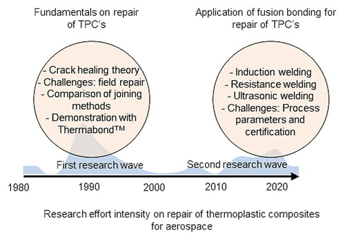
To understand the current state-of-the art within the context of this paper, an extensive review was conducted. Over 200 documents, including a combination of journal articles, conference papers, technical reports and thesis were reviewed. These documents included keywords such as thermoplastics, repair, the different fusion bonding techniques (i.e. induction, resistance, ultrasonic) and how these are used in the aerospace industry. From this search, only 36 articles were found to be relevant to construct a timeline of the evolution of thermoplastic repair along with its current state of the art.
Jaquish et al. [Citation173] mentioned for the first time the need to repair TPC’s in 1980. In this work, the suitability of using thermoplastic resins as adhesives with resistance heating and glue guns was investigated. Adherends joined with thermoplastic adhesives attained strengths of 6.8 MPa while those bonded with a glue gun were unsuccessful as the resin was not fully melted. Shortly after in 1981, Wool et al. [Citation92, Citation93] published a theory on the mechanisms of crack healing of a thermoplastic-thermoplastic interface. In this theory, temperature and pressure are identified as the mechanisms which govern bond formation and intimate contact. Relationships for strength, elongation to break, impact energy and fracture parameters were supported with the experimental data for single crack healing. Follow up work was reported by Unger et al. [Citation174], who first studied healing of impact or fatigue damaged carbon fibre PEEK substrates. These carbon fibre PEEK substrates were repaired using a localized melt zone following rapid cool-down under pressure. Preliminary results showed 95% recovery in buckling load up to 1.6 kN, and a five-fold increase in fatigue life of the specimens, surpassing 106 cycles. These results supported the hypothesis that reinforced thermoplastics could be healed by using local heat and pressure. shows a schematic of a healed substrate after heat and pressure have been applied to flatten the damaged area, bringing broken fibre ends together to repair.
Figure 15. Healing of a damaged substrate by using heat and pressure, with a close-up of the repaired area (adapted from [Citation174]).
![Figure 15. Healing of a damaged substrate by using heat and pressure, with a close-up of the repaired area (adapted from [Citation174]).](/cms/asset/dc5a586e-dc84-4265-a227-2491aa80c563/yadm_a_2057137_f0015_b.jpg)
Davies et al. [Citation175] used carbon fibre PEEK to assess healing after damage by evaluating the recovered delamination resistance in Mode I. Double cantilever beam, 24-ply unidirectional laminates were partially opened, obtaining a baseline value of 2110 Jm−2. The specimens were healed at 1.4 MPa at 325 °C for 45 min, and at 345, 360, 370, and 380 °C for 5 min, and retested. The fracture surfaces at the highest temperatures (i.e. 370 and 380 °C) were similar to those of the baseline specimens. In a second article, Davies [Citation86] compared adhesive bonding, fusion bonding techniques (induction, resistance, and ultrasonic welding), compression moulding and amorphous bonding, and evaluated them for repair. Carbon fibre PEEK was repaired via adhesive bonding, using induction, resistance, and ultrasonic welding. The specimens were drilled with a hole at the centre to simulate perforation damage, as shown in a). The damaged panels were then repaired by applying a patch, as shown in b). The repairs conducted with adhesive bonding were performed with and without a 30 s chromic acid etch while the repairs with fusion bonding utilized additional PEI and PEEK resin films without any surface preparation. Both patched and unpatched specimens were tested in tension and compared to undamaged specimens. The specimens repaired using compression moulding with PEI and adhesive bonding with an acid etch recovered most of the undamaged strength of 745 MPa. The compression moulded specimens, however, displayed smaller standard deviations of 25 MPa. The specimens repaired using resistance welding attained values of almost 650 MPa using a PEI film.
Figure 16. Configuration of tested specimens a) with a hole to simulate damage and b) repaired specimen configuration for tensile test (adapted from [Citation86]).
![Figure 16. Configuration of tested specimens a) with a hole to simulate damage and b) repaired specimen configuration for tensile test (adapted from [Citation86]).](/cms/asset/c8e2df42-59d6-4e19-95db-b6ddb795b8a4/yadm_a_2057137_f0016_b.jpg)
Several more articles related to repair were published from the mid-80s up to 1996. Stein et al. [Citation87] and Clark et al. [Citation88] were the first authors to outline the challenges of aircraft field repair, summarized in . Rapid adhesive bonding was explored by Stein et al. [Citation87] to address these challenges using induction heating with both thermoset and thermoplastic as the adherends. Sivy [Citation176] applied fast-curing patches to metals and thermoplastic structures, demonstrating that this technique tackled most of the challenges of field repair. The patch was able to sustain 70% of the design load of 28 MPa, even in hot and humid environments (40 °C and 100%RH). Westerman et al. [Citation169] presented a prototype of a mechanical scarfing apparatus to improve the preparation of damaged areas for repair and to reduce the variability of the manual-scarfing process on graphite/PEEK structural panels. The prototype reduced the scarfing time from 16 h down to four for carbon fibre PEEK specimens.
Table 4. Challenges of aircraft field repair [Citation87, Citation88].
In 1989, Silverman et al. [Citation26] presented six different joining techniques including fusion bonding methods for assembly of TPC’s, which have been identified as methods with the potential for repair. The samples joined using FM300 attained the highest lap shear strength of 41.6 MPa, followed by the substrates joined with an amorphous layer of Ultem PEI as the adhesive, attaining single lap shear values of 35.6 MPa. At the same time, other researchers worked on joining and repair of TPC’s using dual polymer bonding (i.e. bonding with an amorphous layer) [Citation89, Citation141, Citation177, Citation178]. Smiley et al. [Citation177] and Cogswell et al. [Citation89] presented it as the Thermabond™ technique with the PEI polymer interlayer fused to the surface of each of the substrates. Single lap shear strengths of 41.3 MPa were obtained without any surface preparation (specimens were only cleaned with isopropanol alcohol). While this process has clear advantages from a repair point of view, the main disadvantage is the poor chemical performance of PEI. To address this challenge, Meakin et al. [Citation178] proposed Thermabond™ II, which used a semi-crystalline layer of aromatic polyetherketone (PK99) as the interlayer instead of amorphous PEI. Tensile strengths of 25 MPa and 30 MPa were obtained when bonding at 290 °C and 310 °C, which corresponded to the temperatures below and above the crystalline melting point of the material, respectively. Simultaneously, Niu et al. [Citation179] mentioned the importance of developing repair methods for thermoplastic materials and the possibility of using induction or resistance heating with the dual polymer bonding process. In this work, a mechanical tool (shown in ) was presented where heat and pressure were applied locally for different patch designs.
Figure 17. Schematic of the tool being used for field repair on a curved panel (adapted from [Citation179]).
![Figure 17. Schematic of the tool being used for field repair on a curved panel (adapted from [Citation179]).](/cms/asset/b86f6438-e169-4616-a587-740bf5143da7/yadm_a_2057137_f0017_c.jpg)
A few years later in 1994, Heimerdinger et al. [Citation141] from the Northrop Grumman Corporation demonstrated the Thermabond™ process for a repair of an aircraft structure. At first, a preliminary screening study was performed evaluating induction, resistance and ultrasonic welding to generate heat at the bondline of welded single-lap shear specimens with a 25.4 by 25.4 mm overlap using PEEK resin film at the interface. The PEEK substrates joined with induction and ultrasonic welding showed single lap shear tensile strengths and high standard deviations of 29.9 ± 5.4 and 19.4 ± 5.8 MPa, respectively. On the other hand, specimens joined with resistance welding displayed the highest apparent single lap shear strength of 31.5 MPa with the lowest standard deviations of 3.3 MPa. These results are shown in .
Figure 18. Apparent single lap shear test results comparing fusion bonding techniques with PEEK substrates. The error bars represent the standard deviation (data taken from [Citation141]).
![Figure 18. Apparent single lap shear test results comparing fusion bonding techniques with PEEK substrates. The error bars represent the standard deviation (data taken from [Citation141]).](/cms/asset/9c9063fe-0ae9-4259-9c73-9884cb12ec2e/yadm_a_2057137_f0018_c.jpg)
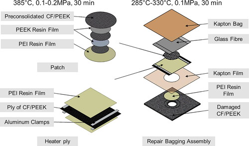
Thus, resistance welding was selected as the method for the repair using a carbon fibre heating element. Performing the repair on large components at temperatures above 385 °C resulted in delaminations whereas temperatures below 385 °C were considered inadequate for repair. Thus, a layer of PEI resin film (instead of the PEEK resin film layer) was used to conduct the repair at temperatures below Tm of the carbon fibre PEEK structure. This has been thus far the only demonstration reported to date of a thermoplastic repair onto an aircraft structure using resistance welding. This process was long and the preparation of the patch had multiple steps which were cumbersome (i.e. the need to generate multiple tools). illustrates the three main elements of the Thermabond™ which include the patch, the heater ply (i.e. carbon fibre layer as the heating element, surrounded by PEI resin film), and the bagging assembly used to conduct the repair. Research on repair of thermoplastics continued to focus on fusion bonding techniques such as induction heating in combination of vacuum pressure [Citation85, Citation106, Citation115], and thermoforming [Citation18, Citation180] for repair of PEEK components.
Figure 19. Patch, heater ply and bagging assembly used in the Thermabond™ process.
In 1994, Xiao et al. [Citation33] published the first review on thermoplastic composite repair where a classification of damage modes (i.e. matrix and fibre damage) and their corresponding repair methods were provided. This classification is represented graphically in .
Figure 20. Damage modes and their classification (adapted from [Citation33]).
![Figure 20. Damage modes and their classification (adapted from [Citation33]).](/cms/asset/783a3c29-6dd6-4d90-8e1b-dc33a7e2e003/yadm_a_2057137_f0020_c.jpg)
Fusion bonding techniques were deemed to be the preferred method for repair due to the minimum surface preparation required and the speed at which a joint is bonded together. A second comprehensive review on thermoplastics for airframe applications along with their repair methods was published shortly after by Vodicka [Citation34]. Induction and resistance heating with an amorphous thermoplastic film, and the Thermabond™ process were deemed to be the most promising methods for field composite repair. The challenge remained, however, in finding a film that is able to withstand a wide range of solvents and environmental degradation. After this review was published, the amount of research on the subject was significantly reduced for a decade. This gap coincided with the development of toughened epoxies and their use in aircraft structures [Citation181].
In the mid-2000s, TPC’s and fusion bonding started to gain momentum again. In 2006, Lawrence et al. [Citation182] used a high power diode laser to melt a thermoplastic adhesive placed between the surface of a patch made out of APC-2 to be bonded to an Alclad substrate. The bond strength with the laser radiation method was 47.8 MPa, compared to 34.4 and 41.7 MPa for induction and resistance welded samples, respectively. In the 2010s, Kaden et al. [Citation183, Citation184] implemented a laser support to prepare the stepped-lap repair joints on PEEK substrates. Two mechanisms of heat generation at the interface were also explored: resistance heating using a stainless steel mesh with a pressure application tool, and induction heating using heated metallic sheets under vacuum pressure. The authors concluded that despite the challenges of induction welding, the technique was suitable for patch repair without the need to add a mesh at the interface. Sunar et al. [Citation185] followed up this research by performing an economic comparison between thermoset and TPC repair using the methods established by Kaden [Citation183, Citation184], finding that a third of the time can be saved (from 17 h to only six hours to conduct a repair) and 64% of the labour cost (from $2660 USD down to approximately $900 USD) by using induction and resistance heating. Nijhuis et al. [Citation186] in collaboration with Fokker aerospace explored methods to repair thin walled structures (i.e. 2 mm thick) made out of carbon fibre PEKK using standard tools such as a heating blanket, infrared heater and a heating gun. The author stated that a delamination can be repaired by melting the material and by adding a patch over the damaged area. A schematic of their setup is shown in . The challenges of using a heating blanket was the thermal expansion of the caul plate and the material, causing the repair patch to be curved. The repairs conducted using the infrared heater also resulted in curved patches with wrinkling of the bottom surface. Finally, repairs conducted using a heat gun needed a metal disk and dead weight to apply 0.5 MPa of pressure, which would represent a challenge when repairing curved structures as an exact metal disk replicating the shape of the parent structure would be needed.
Figure 21. Setup of the repair with a heat blanket (diagram adapted from [Citation186]).
![Figure 21. Setup of the repair with a heat blanket (diagram adapted from [Citation186]).](/cms/asset/08626b81-f456-4b57-a5d4-04646700c48b/yadm_a_2057137_f0021_c.jpg)
Vaur [Citation123] investigated the use of induction welding to perform a patch repair with carbon fibre PPS, as shown in . In this work, 93% of the original tensile strength of 608 MPa was recovered by applying a lap joint on the damaged area.
Figure 22. Patch repair using CF/PPS and induction welding (adapted from [Citation123]).
![Figure 22. Patch repair using CF/PPS and induction welding (adapted from [Citation123]).](/cms/asset/1be1020f-86b5-47c4-8de5-7bd6acb8f9d1/yadm_a_2057137_f0022_c.jpg)
Follow up work was conducted by Côté [Citation124, Citation187] using continuous induction welding to repair impacted carbon fibre PEEK substrates. The undamaged, damaged, and repaired substrates were tested in three-point bending where the repaired specimens attained 138% of the original strength. Miyake et al. [Citation188] used induction heating to increase the temperature of carbon fibre specimens, observing a flexural modulus increase of up to approximately 6.5 GPa due to interfacial re-consolidation. Toyoda et al. [Citation189] explored the possibility of using ultrasonic welding to repair notched specimens from one side only using multiple patches with a thermoplastic layer. The flexural properties of the specimens were recovered on ultra-thin carbon fibre tape thermoplastics to the undamaged values of up to 800 N when using four patches or more on the damaged area.
Another challenge for repair is attaining the high consolidation pressures needed in fusion bonding. Schwanemann et al. [Citation190] proposed a thermoplastic patch placement (TPP) process using pre-consolidated thermoplastic sheets with generative manufacturing. The authors demonstrated that the TPP process has the potential for repairing thermoplastic structures with curved surfaces, with changes in thickness and varying fibre orientations. Gallo et al. [Citation191] recently obtained a patent for an innovative technique called the high pressure repair dome (HPRD) to bond or co-cure a composite prepreg patch under a pressurized dome which can be used on curved surfaces. The setup, shown in , allowed the use of a heating blanket to conduct the repair. This configuration has not yet been explored with TPC’s.
Figure 23. Setup of the high pressure repair dome used to co-cure a composite prepreg patch on a curved surface (adapted from [Citation191]).
![Figure 23. Setup of the high pressure repair dome used to co-cure a composite prepreg patch on a curved surface (adapted from [Citation191]).](/cms/asset/3386b2a2-1752-428b-a368-0259d8807ee9/yadm_a_2057137_f0023_c.jpg)
Lastly, at the end of 2020, Reis et al. [Citation32] published a review on the three most promising fusion bonding techniques for repair (i.e. induction, resistance, and ultrasonic welding). In this review, the TPC materials used with each of these techniques and adhesive bonding were identified. Other aspects such as strength testing, NDI, and numerical modelling were also presented.
shows a graphical summary of the articles published on repair of TPC’s in chronological order. The details of each article include select highlights which are provided in .
Figure 24. Timeline of thermoplastic composite repair. The blue envelope represents the density of work conducted on the subject over time.
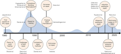
Table 5. Detailed summary of the articles presented in on repair of TPC’s.
5. Summary and present challenges
An extensive literature review was conducted finding that the field of repair of TPC’s started in 1980. A first wave of published research on the subject was observed up to the mid-90s. During this time, the theory of crack healing was developed. The utilization of fusion bonding techniques, mainly induction, resistance and ultrasonic welding along with bonding using an amorphous layer on PEEK substrates was explored [Citation26, Citation32–34, Citation86]. The Thermabond™ process was developed and applied to conduct a demonstration of a patch repair using resistance welding on an aircraft structure in 1994, marking the apex of this first repair era. As these materials are being adopted for the aircraft of the next generation, a second wave of research has been observed in the last decade, focusing again on fusion bonding and repair of TPC’s. By exploring a wide range of techniques, it would be possible to develop a versatile, and adaptable repair methodology.
In terms of other innovative solutions, additive manufacturing (AM) has been recently explored in the context of repair [Citation193]. Carbon fibre and fibre glass patches were manufactured and bonded using a thermoset film and paste adhesive. This approach has not been yet explored in TPC’s and the technology is not considered to be mature for repair. However, the aerospace industry is increasingly using AM [Citation194] and certification organizations such as FAA and EASA have been working on moving away from a prescriptive to a performance-based certification approach [Citation195]. This change would allow to certify structures which demonstrate they underwent a robust manufacturing process and are able to withstand ultimate load. The application of new technologies would be done on a case-by-case basis with close guidance from the certification authorities.
It is evident that challenges and gaps on the subject still remain. The challenges are summarized below:
In terms of certification, fusion bonding is not considered to be a technology mature enough to be used for repair at the present time
Lack of robust processes to produce consistent and repeatable results when using fusion bonding
High consolidation pressures needed in the fusion bonding process, and eventually in repair of TPC’s
Inability to accurately monitor and control the temperature at the interface for the most promising fusion bonding techniques
Lack of suitable simulation tools for TPC repair
The summary of the gaps that were identified in the literature is as follows:
Lack of data on TPC materials other than PEEK (techniques developed in the 90s have not been explored with other semi-crystalline materials, including newer material systems)
An understanding of the predominant mechanisms in the dual polymer bonding process using an amorphous and semi-crystalline layer which can lead to a robust repair methodology
Use of existing technologies such as AM for repair of TPC’s has not been reported
Data is missing on susceptibility to surface contamination with multiple material systems
Earlier research has focused on exploring one fusion bonding technique at a time for repair. However a combination of these methods has not yet been explored
Solutions to attain high pressures such as the HPRD been shown with thermoset polymer matrix composites, however, such setups have not been developed to be used with TPC’s
Lack of simulation tools which can be used to develop processes and a robust methodology for repair of TPC’s
6. Conclusions
TPC’s are increasingly being used in aerospace structures for both load and non-load bearing applications. TPC materials have remarkable properties allowing to further reduce the number of plies in structures when compared to thermoset polymer matrix composites while showing high impact, fatigue and solvent resistance performance. To fully take advantage of these materials, robust repair methodologies need to be developed which can be accepted by the certification authorities.
Fusion bonding has been presented as a solution to join and repair TPC’s, which does not require any surface preparation. The three most promising techniques which have been identified are induction, resistance, and ultrasonic welding along with the use of an amorphous layer as an adhesive. AM could have the potential to create patches which conform better to the parent structure minimizing the need of additional tooling.
Challenges still remain before a methodology is developed, including an accurate control of the temperature at the interface and attaining the high consolidation pressures needed to create intimate contact between the adherends. A robust and systematic methodology along with consistency in the mechanical performance of the welded joints are needed in order for a repair technology to be certified. These challenges must be addressed before TPC’s materials can be fully implemented on aircraft structures.
Acknowledgments
The authors of this paper would like to acknowledge the valuable technical feedback and support received by Dr. Adam W. Smith from École de Technologie Supérieure.
Disclosure statement
No potential conflict of interest was reported by the authors.
Data availability statement
Data sharing is not applicable to this article as no new data were created or analyzed in this study.
Additional information
Funding
References
- Sloan J. The first composite fuselage section for the first composite commercial jet. 2018. [cited 2021 Feb 22]; Available from: https://www.compositesworld.com/articles/the-first-composite-fuselage-section-for-the-first-composite-commercial-jet.
- Marsh G. Airbus A350 XWB update. Composite applications 2010. [cited 2021 Feb 22]; Available from: https://www.materialstoday.com/composite-applications/features/airbus-a350-xwb-update/#.:∼:text = In%20fact%2C%20the%20billed%2053,steel%20and%208%25%20other%20materials.
- Macdonald JP. Bombardier Aerospace granted authority to offer CSeries aircraft to customers. 2005. [cited 2021 Feb 22]; Available from: https://bombardier.com/en/media/news/bombardier-aerospace-granted-authority-offer-cseries-aircraft-customers-0?page=0&category=All&year=2005&month=3.
- Ingen JW, et al. Development of the gulfstream G650 induction welded thermoplastic elevators and rudder. SAMPE. Seattle, WA; 2010.
- Partnering the aircraft of the future. 2019. [cited 2021 Feb 22]; Available from: https://www.gknaerospace.com/en/newsroom/downloadable-materials/.
- Gardiner G. Thermoplastic composite demonstrators - EU roadmap for future airframes. Processes 2018. Available from: https://www.compositesworld.com/articles/thermoplastic-composite-demonstrators-eu-roadmap-for-future-airframes-.
- Sloan J. TAPAS 2: next steps in thermoplastic structures. High performance composites. Cincinnati, Ohio; 2014.
- Sloan J. Fokker aerostructures: Hoogeveen, The Netherlands. 2015. [cited 2021 Feb 23]; Available from: https://www.compositesworld.com/articles/fokker-aerostructures-hoogeveen-the-netherlands.
- TAPAS. 2021. About us. [cited 2021 Aug 2]; Available from: http://www.tapasproject.nl/en/about-us.
- Black S. Thermoplastic composites "clip" time, labor on small but crucial parts. 2015. [cited 2021 Sept 9]; Available from: https://www.compositesworld.com/articles/thermoplastic-composites-clip-time-labor-on-small-but-crucial-parts.
- Black S. Composite brackets for life-of-aircraft service. 2015. [cited 2021 Sept 9]; Available from: https://www.compositesworld.com/articles/composite-brackets-for-life-of-aircraft-service.
- Gregory H, and Taylor E. Bombardier announces £70 million in supplier contracts to support wing production in Northern Ireland. Aviation 2011. [cited 2021 Sept 9]; Available from: https://bombardier.com/en/media/news/bombardier-announces-ps70-million-supplier-contracts-support-wing-production-northern.
- PEEK aerospace bracket for Bombardier aircraft drive down manufacturing costs 2015. [cited 2021 Sept 9]; Available from: https://www.plasticstoday.com/peek-aerospace-brackets-bombardier-aircraft-drive-down-manufacturing-costs.
- Gardiner G. Thermoplastic composites: Inside story. 2009. [cited 2022 Jan 10]; Available from: https://www.compositesworld.com/articles/thermoplastic-composites-inside-story.
- Gardiner G. Aerospace-grade compression molding. Thermoplastics 2010. [cited 2022]; Available from: https://www.compositesworld.com/articles/aerospace-grade-compression-molding.
- Hautier M, Lévêque D, and Huchette C, et al. Investigation of composite repair method by liquid resin infiltration. Plast Rubber Compos. 2010; 39(3–5) :200–207.
- Yousefpour A, Hojjati M, and Immarigeon J-P. Fusion bonding/welding of thermoplastic composites. J Thermoplast Compos Mater. 2004;17(4):303–341.
- Ong C-L, Sheu M-F, and Liou Y-Y. The repair of thermoplastic composites after impact. 34th international SAMPE symposium. Reno, Nevada; 1989.
- Stokes VK. Joining methods fors plastics and plastic composites. Polym Eng Sci. 1989; 29(19) :1310–1324.
- Mathijsen D. Thermoplastic composites keep gaining momentum in the automotive industry. Reinf Plast. 2016; 60(6) :408–412.
- Ishikawa T, Amaoka K, Masubuchi Y, et al. Overview of automotive structural composites technology developments in Japan. Compos Sci Technol. 2018; 155 :221–246.
- Gardiner G. Carbon fiber will enable air taxi eVTOLs. Urban Air Mobility 2019. [cited 2021 Sept 21]; Available from: https://www.compositesworld.com/articles/carbon-fiber-will-enable-air-taxi-evtols.
- Red C. Thermoplastics in aerospace composites outlook. Thermoplastics 2014. [cited 2021 Sept 21]; Available from: https://www.compositesworld.com/articles/the-outlook-for-thermoplastics-in-aerospace-composites-2014-2023.
- Mallick PK. Fiber-reinforced composites: materials. In: Manufacturing, and design. 3rd ed. Dearborn, MI: C. Press; 2007.
- Anonymous. Email exchange - cost of repair vs. replacement of aircraft structures. In: Barroeta Robles J, editor. Montreal, QC; 2021.
- Silverman EM, and Griese RA. Joining methods for graphite/peek thermoplastic composites. Sampe J. 1989; 25(5) :34–38.
- Ageorges C, Ye L, and Hou M. Advances in fusion bonding techniques for joining thermoplastic matrix composites: a review. Compos Part A. 2000; 32 :239–857.
- Ageorges, C. and L. Ye, Fusion bonding of polymer composites: from basic mechanisms to process optimisation engineering materials and processes. London: Springer; 2002.
- Todd SM, and Michelove Leon D, et al. Joining thermoplastic composites. 22nd International SAMPE Technical Conference. Boston, MA, USA; 1990. p. 383–392.
- Grefe H, et al. Fusion bonding of fiber reinforced thermoplastics and thermosets. ECCM17 - 17th european conference on composite materials. Munich, Germany; 2016. p. 1–9.
- Benatar A, and Gutowski TG. Methods for fusion bonding of thermoplastic composites. SAMPE J. 1987; 23(1) :33–39.
- Reis JP, Moura MD, and Samborski S. Thermoplastic composites and their promising applications in joining and repair composites structures: a review. Materials. 2020; 13(24) :5832–5833.
- Xiao X, Hoa SV, and Street KN. Repair of thermoplastic resin composite by fusion bonding. Philadelphia, PA: American Society for Testing and Materials; 1994.
- Vodicka R. Thermoplastic for airframe applications: a review of the properties and repair methods for thermoplastic composites. United States: Aeronautical and Maritime Research Laboratory; 1996.
- Campbell FC. Chapter 1 - introduction, in manufacturing technology for aerospace structural materials. In: Campbell FC, editor. Oxford: Elsevier Science; 2006. p. 1–13.
- Baker A, Dutton S, and Kelly D. 1.5 Matrices. In: Composite materials for aircraft structures. 2nd ed. Reston, VA: American Institute of Aeronautics and Astronautics (AIAA); 2004.
- Park S-J, and Seo M-K. Chapter 6 - Element and processing. In: S.-J. Park and M.-K. Seo, editors. Interface science and technology. Oxford, UK: Elsevier; 2011. p. 431–499.
- Bibin J, and Nair CPR. 13 - Syntactic foams. In: Dodiuk H and Goodman SH, editors. Handbook of thermoset plastics. 3rd ed. Boston: William Andrew Publishing; 2014. p. 511–554.
- Campbell FC. Chapter 3 - thermoset resins: the glue that holds the strings together. In: Manufacturing processes for advanced composites. In: Campbell FC, editor. Elsevier Science: Amsterdam; 2004. p. 63–101.
- Shimp DA. Speciality matrix resins. In: Peters ST, editor. Handbook of composites. Boston, MA: Springer US; 1998. p. 99–114.
- Guenthner A, Yandek G, and Mabry J. Insights into moisture uptake and processability from new cyanate ester monomer and blend studies. CA, USA: Air Force Research Laboratory; 2010
- AMC 20-29 effective: annex II to ED decision - composite aircraft structure. 2010.
- Preau M. Defect management in vacuum bag only semipreg processing of co-bonded composite repairs. In: Mechanical engineering. Montreal, Quebec: McGill University; 2016.
- Seipel JD. Policy statement: Bonded repair size limits. 2014. Federal Aviation Administration: USA.
- Larson ER. 3 - Understanding thermoplastics. In: Larson ER, editor. Thermoplastic material selection. Oxford, UK: William Andrew Publishing; 2015 p. 57–95.
- Wypych G. PEEK polyetheretherketone. In: Wypych G, editor. Handbook of polymers. 2012. Elsevier: Oxford. p. 353–358.
- Wypych G. PEKK polyetherketoneketone. In: Wypych G, editor. Handbook of polymers. 2012. Elsevier: Oxford. p. 367–369.
- Wypych G. 2015. Handbook of polymers. In: Wypych G, editor. Elsevier: Oxford; 2012. p. 511–515.
- Wypych G. PEI poly(ether imide). In: Wypych G, editor. Handbook of polymers. Elsevier: Oxford; 2012. p. 359–363.
- Black S. Thermoplastic composites technology: a view from Europe. CompositesWorld. Cincinnati, OH: Gardner Business Media Inc.; 2015. [cited 2021 Sept 29]; Available from: https://www.compositesworld.com/articles/thermoplastic-composites-technology-a-view-from-europe.
- Huo W, Zhang W. Advanced composite materials defects/damages and health monitoring, in Prognostics and System Health Management Conference. Beijing; 2012.
- CMH17: PMC's materials usage design and analysis. In: rev G, Wichita, KS: SAE International. CMH-17. 2014.
- Dubinskiy S. A study of accidental impact scenarios for composite wing damage tolerance evaluations. Aeronaut J. 2019;123(1268):1724–1739.
- Sauer C. Lufthansa perspective on applications and field experiences for composite airframe structures. In: Comercial aircraft composite repair committee. (CACRC) Meeting; 2007; Wichita, KS.
- Ilcewicz L, Cheng L, Hafenricher J. Guidelines for the development of a critical composite maintenance and repair issues awareness course. In: Administration FA, editor. Washington, DC: 2009.
- Kim J. Damaged composite aircraft structure due to lighting strike. 2022.
- Collombet F, et al. 10 - Repairing composites. In: Boisse P, editor. Advances in composites manufacturing and process design. Cambridge, UK: Woodhead Publishing; 2015. p. 197–227.
- Service Difficulty Reports. Data Downloads 2021. [cited 2021 May 21]; Available from: https://av-info.faa.gov/dd_sublevel.asp?Folder=%5CSDRS.
- Raju IS, O'Brien TK. Fracture mechanics concepts, stress fields, strain energy release rates, delamination initiation, and growth criteria. In: U. NASA-Langley Research Centre, editor. Delamination behaviour of composites. 2008. Cambridge, UK: Woodhead Publishing Series in Composites Science and Engineering.
- Wronkowicz-Katunin A. A brief review on NDT&E methods for structural aircraft components. Fatigue Aircr Struct. 2018;2018(10):73–81.
- Aircraft inspection for the general aviation aircraft owner. 1978. U.S Department of Transportation.
- Guide to aircraft inspections. 2021. [cited 2021 Sept 10]; Available from: https://www.aopa.org/go-fly/aircraft-and-ownership/maintenance-and-inspections/aircraft-inspections.
- EASA. EASA Proposed CM-S-005 Issue 01 - Bonded repair size limits in accordance with CS-23, CS-28, CS-27, CS-29 and AMC 20-29 - Comment response document; 2015.
- Davis MJ. A rigorous approach to certification of adhesive bonded repairs. In: FAA workshop on certification of adhesive bonded structures and repairs. MIL HDBK 17 Meeting; 2004; Seattle WA.
- AIR-100. Bonded repair size limits. In: Policy statement. Washington, DC: Federal Aviation Administration; 2014.
- Wang CH, Duong CN. Chapter 4 - Design of scarf and doubler-scarf joints. In: Bonded joints and repairs to composite aiframe structures. London, UK: Academic Press; 2016.
- Anonymous. Personal communications on the repair of thermoset and thermoplastic composites. Robles JB, editor. Montréal, QC; 2021.
- Archer E, McIlhagger A. 14 - Repair of damaged aerospace composite structures, in polymer composites in the aerospace industry. Irving PE and Soutis C, editors. Kidlington, UK: Woodhead Publishing; 2015. p. 393–412.
- Tomblin JS, et al. Effects of repair procedures on bonded repairs of airframe structures. 2017. Wichita, KS: The U.S. Department of Transporation/Federal Aviation Administrator.
- Davis M, Tomblin J. Best practice in adhesive-bonded structures and repairs. Wichita, KS: Federal aviation administration. National Technical Information Services; 2007.
- Seneviratne WP, Tomblin JS, Saathoff BL. Influence of various surface preparation techniques on resistance welded and adhesively bonded unidirectional thermoplastic composite joints. SAMPE Conference Proceedings; 2021 May 24–27; Long Beach, CA; SAMPE.
- Baker A. Development of a hard-patch approach for scarf repair of composite structure. In: Defence science and technology organisation document control data. Australia: Air Vehicles Division, DSTO Defence Science and Technology Organisation; 2006.
- Armstrong KB, Bevan LG, Cole WF. 9.3.6 Room-temperature wet lay-up. In: Care and repair of advanced composites. 2nd ed. Warrendale, PA: SAE International; 2005.
- Armstrong KB, Bevan LG, Cole WF. 9.3.8 Pre-preg repairs. In: Care and repair of advanced composites. 2nd ed. Warrendale, PA: SAE International; 2005.
- Jones JS, Graves SR. Repair techniques for celion/LARC-160 graphite/polyimide composite structures. Report NC, editor. Contractor Report, Downey, CA: Rockwell International; 1984.
- Wang CH, Gunnion AJ. Optimum shapes for minimising bond stress in scarf repairs. Aust J Mech Eng. 2008;6(2):153–158.
- Darwish FH, Shivakumar KN. Experimental and analytical modeling of scarf repaired composite panels. Mech Adv Mater Struct. 2014;21(3):207–212.
- Olajide SO, Kandare E, Khatibi AA. Fatigue life uncertainty of adhesively bonded composite scarf joints - an airworthiness perspective. J Adhes. 2017; 93(7) :515–530.
- Armstrong KB, Bevan LG, Cole WF. 9.1 Component identification. In: Care and repair of advanced composites. 2nd ed. Warrendale, PA: SAE International; 2005.
- Bishopp J. Chapter 4 surface pretreatment for structural bonding. In: Cognard P, editor. Handbook of adhesives and sealants. Oxford, UK: Elsevier Science Ltd; 2005. p. 163–214.
- Kutz M. Chapter 26 - Plastics joining. In: Applied plastics engineering handbook: Processing, materials, and applications. 2nd ed. Oxford, UK: Elsevier; 2017.
- Davies P, Courty C, Xanthopoulos N, et al. Surface treatment for adhesive bonding of carbon fibre-Poly(etherether ketone) composites. J Mater Sci Lett. 1991;10(6):335–338.
- Krieg KL, et al. Structural adhesive bonding of thermoplastics. SAMPE Conference Proceedings; 2014 June 2–5; Seattle, WA. SAMPE.
- Russell AJ, Ferguson JS. Composite repair issues on the CF-18 aircraft. 79th meeting of the AGARD structures and materials panel. 1994. Seville, Spain.
- Rodgers B, Mallon PJ. Part II: Repair of thermoplastic composites using induction heating. In: S Trans Tech Publications Ltd, editor. Key Engineering Materials: Materials for Advanced Technology Applications. Composites Manufacturing Research Unit, University of Limerick: Switzerland; 1992.
- Davies P, Cantwell WJ, Jar P-Y, et al. Joining and repair of a carbon fibre-reinforced thermoplastic. Composites. 1991;22(6):425–431.
- Stein BA. Rapid adhesive bonding and field repair of aerospace materials. USA: NASA-Langley Research Centre; 1986.
- Clark EC, Cressy KD. Field repair compounds for thermoset and thermoplastic composites. In: ICBT '86: Proceedings of the international workshop on ionized cluster beam technique. Covina, CA, USA: SAMPE; 1987.
- Cogswell FN, et al. Thermoplastic interlayer bonding for aromatic polymer composites. 34th International SAMPE Symposium 1989.
- Cochran R, Gunther G. Recorder's report. Composite repair of military aircraft structures. AGARD Conference Proceedings, Seville, Spain; 1995. p. 550.
- Kinloch AJ, Kodokian GKA, Watts JF. Relationships between the surface free energies and surface chemical compositions of thermoplastic fibre composites and adhesive joint strengths. J Mater Sci Lett. 1991;10(14):815–818.
- Kim YH, Wool RP. A theory of healing at a polymer-polymer interface. Macromolecules. 1983;16(7):1115–1120.
- Wool RP, O’Connor KM. A theory crack healing in polymers. J Appl Phys. 1981;52(10):5953–5963.
- Yang F, Pitchumani R. Healing of thermoplastic polymers at an interface under nonisothermal conditions. Macromolecules. 2002;35(8):3213–3224.
- Ageorges C. Characteristics of resistance welding of lap shear coupons. Part I: heat transfer. Composites Part A. 1998;29A:899–909.
- Gennes PGd. Reptation of a polymer chain in the presence of fixed obstacles. The Journal of Chemical Physics. 1971;55(572):572–579.
- Loos AC, Dara PH. Processing of thermoplastic matrix composites. Boston, MA: Springer US; 1987.
- Jud K, Kausch HH, Williams JG. Fracture mechanics studies of crack healing and welding of polymers. J Mater Sci. 1981;16(1):204–210.
- Prager S, Tirrell M. The healing process at polymer-polymer interfaces. J Chem Phys. 1981;75(10):5194–5198.
- Wedgewood R. and Hardy PE. Induction welding of thermoset composite adherends using thermoplastic interlayers and dusceptors. 28th International SAMPE Technical Conference; 1996 Nov. 4–7. p. 850–861.
- Ahmed TJ, Stavrov D, Bersee HEN, et al. Induction welding of thermoplastic composites - an overview. Compos Part A Appl Sci Manuf. 2006;37(10):1638–1651.,
- Rudolf R, Mitschang P, Neitzel M. Induction heating of continuous carbon-fibre-reinforced thermoplastics. Compos Part A Appl Sci Manuf. 2000;31(11):1191–1202.
- Mitschang P, Rudolf R, Neitzel M. Continuous induction welding process, modelling and realisation. J Thermoplast Compos Mater. 2002;15(2):127–153.
- Yarlagadda S, Kim HJ, Gillespie JW, et al. A study on the induction heating of conductive fibre reinforced composites. J Compos Mater. 2002;36(4):401–421.
- Lin W, Miller AK, Baneman O. Predictive capabilities of an induction heating model for complex-shape graphite fiber/polymer matrix composites. 24th International SAMPE Technical Conference; 1992 Oct 20–22; Toronto, Canada. SAMPE.
- Lawless GW, Reinhart TJ. A study of the induction heating of organic composites. Interim Report. Ohio: University of Dayton and Wright Laboratories, Material Directorate; 1992.
- Seneviratne W, et al. Induction heating analysis validation of CF/PEKK laminates with magnetic flux controller. SAMPE Conference Proceedings; 2021 May 24–27; Long Beach, CA. SAMPE. p. 1–13.
- Coey JMD. Applications of soft magnets. In: Magnetism and magnetic materials. Cambridge: Cambridge University Press; 2010. p. 439–463.
- Martin RG, Johansson C, Tavares JR, et al. Material selection methodology for an induction welding magnetic susceptor based on hysteresis losses. Adv Eng Mater. 2022;24(3):2100877.
- Villegas IF, Moser L, Yousefpour A, et al. Process and performance evaluation of ultrasonic, induction and resistance welding of advanced thermoplastic composites. J Thermoplast Compos Mater. 2013;26(8):1007–1024.
- Rahim NAA, et al. In-situ monitoring and control of induction welding in thermoplastic composites using high definition fiber optic sensors. The Composites and Advanced Materials Expo, CAMX. Anaheim, CA; 2019.
- Mahdi S, Kim H-J, Gama BA, et al. A comparison of oven-cured and induction-cured adhesively bonded composite joints. J Compos Mater. 2003;37(6):519–542.
- Lionetto F, Pappadà S, Buccoliero G, et al. Finite element modeling of continuous induction welding of thermoplastic matrix composites. Mater Des. 2017; 120 :212–221.
- Miller A, et al. The nature of induction heating in graphite-fiber, polymer-matrix composite materials. Sampe J. 1990; 26 :37–54.
- Fink BK, McCullough RL, Gillespie JW. A local theory of heating in cross‐ply carbon fiber thermoplastic composites by magnetic induction. Polym Eng Sci. 2004;32(5):357–369.
- Fink BK, McCullough RL, W.G J. Jr, Induction heating of carbon-fiber composites: Electrical potential distribution model. Aberdeen Proving Ground, MD: Army Research Laboratory; 1999.
- Becker S, Michel M, Mitschang P, et al. Influence of polymer matrix on the induction heating behavior of CFRPC laminates. Compos Part B. 2022;231:109561–109515.
- Moser L. Experimental analysis and modeling of susceptorless induction welding of high performance thermoplastic polymer composites. Institut für Verbundwerkstoffe GmbH: Germany; 2012.
- Duhovic M, et al. Further advances in simulating the processing of composite materials by electromagnetic induction in 13th International LS-DYNA Users Conference. 2014.
- Bensaid S, Trichet D, Fouladgar J. 3-D simulation of induction heating of anisotropic composite materials. IEEE Trans Magn. 2005;41(5):1568–1571.
- O'Shaughnessey PG, Dubé M, Villegas IF. Modeling and experimental investigation of induction welding of thermoplastic composites and comparison with other welding processes. J Compos Mater. 2016;50(21):2895–2910.
- Gardiner G. Welding thermoplastic composites. 2018. [cited 2022 March 11]; Available from: https://www.compositesworld.com/articles/welding-thermoplastic-composites
- Vaur R. Développement de méthodes de réparation des composites à matrice thermoplastique utilisant le soudage par induction, in génie méchanique. Montreal, QC: École de Technologie Supérieure; 2015.
- Côté N. Réparation de composites à matrice thermoplastique en utilisant la soudure par induction. Génie mécanique. Montreal, QC: École de Technologie Supérieure; 2018.
- Ageorges C, Ye L, Hou M. Experimental investigation of the resistance welding of thermoplastic-matrix composites. Part II: optimum processing window and mechanical performance. Compos Sci Technol. 2000;60(8):1191–1202.
- Brassard D, Dubé M, Tavares JR. Resistance welding of thermoplastic composites with a nanocomposite heating elements. Compos Part B. 2019; 165 :779–784.
- Yousefpour A, Octeau M-A. Resistance welding of thermoplastic composites. Canada: National Research Council Canada; 2005.
- Endrass M, et al. Towards continuous resistance welding for full-scale aerospace components in SAMPE Europe. Amsterdam: SAMPE Europe; 2020.
- Yousefpour A, Simard M, Octeau MA. Effects of mesh size on resistance welding of thermoplastic composites using metal mesh heating elements. Paris: SAMPE Europe; 2004.
- Yousefpour A. Process optimization of resistance-welded thermoplastic composites using metal mesh heating elements. SAMPE, Long Beach, California, USA; 2005.
- Ageorges C, Ye L, Hou M. Experimental investigation of the resistance welding for thermoplastic matrix composites part I: heating element and heat transfer. Compos Sci Technol. 2000;60(7):1027–1039.
- Stavrov D, Bersee H. Resistance welding of thermoplastic composites - an overview. Compos Part A Appl Sci Manuf. 2005;36(1):39–54.
- Dubé M, Hubert P, Yousefpour A, et al. Current leakage prevention in resistance welding of carbon fibre reinforced thermoplastics. Compos Sci Technol. 2008;68(6):1579–1587.
- Dube M. Static and fatigue behaviour of thermoplastic composite laminates joined by resistance welding. Department of mechanical engineering, McGill University, Montreal, QC. 2007.
- Jakobsen TB, Don RC, W.G J. Jr, Two-Dimensional thermal analysis of resistance welded thermoplastic composites. Polym Eng Sci. 1989;29(23):1722–1729.
- Xiao XR, Hoa SV, Street KN. Processing and modelling of resistance welding of APC-2 composite. J Compos Mater. 1992;26(7):1031–1049.
- Ageorges C, Ye L, Hou M. Characteristics of resistance welding of lap shear coupons. Part II: consolidation. Compos Part A. 1998;98:1359–1835.
- Talbot É, Hubert P, Dubé M, et al. Optimization of thermoplastic composites resistance welding parameters based on transient heat transfer finite element modeling. J Thermoplast Compos Mater. 2013;26(5):699–717.
- Zammar I, Huq MS, Mantegh I, et al. A three-dimensional transient model for heat transfer in thermoplastic composites during continuous resistance welding. Adv Manuf Polym Compos Sci. 2017;3(1):32–41.
- Shi H, Villegas IF, Octeau M-A, et al. Continuous resistance welding of thermoplastic composites: modelling of heat generation and heat transfer. Compos Part A Appl Sci Manuf. 2015;70:16–26.
- Heimerdinger MW. Repair technology for thermoplastic aircraft structures. 79th meeting of the AGARD structures and Materials Panel on "Composite Repair of Military Aircraft Structures". Seville, Spain: Northrop Grumman Corporation; 1994.
- Villegas IF. Ultrasonic welding of thermoplastic composites. Front Mater. 2019;6:291.
- Benatar A, Gutowski TG. Ultrasonic welding of PEEK graphite APC-2 composites. Polym Eng Sci. 1989;29(23):1705–1721.
- Jongbloed B, Teuwen J, Benedictus R, et al. On differences and similarities between static and continuous ultrasonic welding of thermoplastic composites. Compos Part B. 2020;203:108466–108414.
- Levy A, Corre ASL, Villegas IF. Modeling of the heating phenomena in ultrasonic welding of thermoplastic composites with flat energy directors. J Mater Process Technol. 2014;214(7):1361–1371.
- Tateishi N, North TH, Woodhams RT. Ultrasonic welding using tie-layer materials. Part I: analysis of process operation. Polym Eng Sci. 1992;32(9):600–611.
- Ramarathnam G, North TH, Woodhams RT. Ultrasonic welding using tie-layer materials. Part II: factors affecting the lap-shear strength of ultrasonic welds. Polym Eng Sci. 1992;32(9):612–619.
- Fernandez Villegas I, Valle Grande B, Bersee HEN, et al. A comparative evaluation between flat and traditional energy directors for ultrasonic welding of CF/PPS thermoplastic composites. Compos Interfaces. 2015;22(8):717–729.
- Hornstein J. Ultrasonic assembly of plastic parts. Proceedings of the Regional Technical Conference on Decorating; 1996.
- Benatar A, Eswaran RV, Nayar SK. Ultrasonic welding of thermoplastics in the near-field. Polym Eng Sci. 1989;29(23):1689–1698.
- Benatar A, Cheng Z. Ultrasonic welding of thermoplastics in the far-field. Polym Eng Sci. 1989;29(23):1699–1704.
- Li Y, Arinez J, Liu Z, et al. Ultrasonic welding of carbon fiber reinforced composite with variable blank holding force. J Manuf Sci Eng. 2018;140(9):1–11.
- Tutunjian S, Dannemann M, Fischer F, et al. A control method for the ultrasonic spot welding of fiber-reinforced thermoplastic laminates through the weld-power time derivative. J Manuf Mater Process. 2018;3(1):1–17.
- Villegas IF. In situ monitoring of ultrasonic welding of thermoplastic composites through power and displacement data. J Thermoplast Compos Mater. 2015;28(1):66–85.
- Villegas IF. Strength development versus process data in ultrasonic welding of thermoplastic composites with flat energy directors and its application to the definition of optimum processing parameters. Compos Part A Appl Sci Manuf. 2014;65:27–37.
- Bhudolia SK, Gohel G, Leong KF, et al. Advances in ultrasonic welding of thermoplastic composites: a review. MDPI Mater. 2020;13(6):1284–1226. (
- Suresh KS, Rani MR, Prakasan K, et al. Modeling of temperature distribution in ultrasonic welding of thermoplastics for various joint designs. J Mater Process Technol. 2007;186(1–3):138–146.
- Palardy G, Shi H, Levy A, et al. A study on amplitude transmission in ultrasonic welding of thermoplastic composites. Compos Part A Appl Sci Manuf. 2018;113:339–349.
- Jongbloed B, Teuwen J, Palardy G, et al. Continuous ultrasonic welding of thermoplastic composites: enhancing the weld uniformity by changing the energy director. J Compos Mater. 2020;54(15):2023–2035.
- Frederick H, Li W, Palardy G. Disassembly study of ultrasonically welded thermoplastic composite joints via resistance heating. Materials. 2021;14(10):2521–2520.
- Taylor NS, Jones SB, Weld M. The feasibility of welding thermoplastic composite materials. Constr Build Mater. 1989;3(4):213–219.
- Don RC, et al. Application of thermoplastic resistance welding techniques to thermoset composites. Proceedings of the Society of Plastic Engineers. ANTEC 1994; 1994. p. 1295–1299.
- Jacaruso GJ, Davis GC, McIntire AJ. Method of making thermoplastic adhesive strip for bonding thermoset composite structures. Hartford, CT: Google Patents; 1993.
- McIntire AJ, Davis GC. Bonding of thermoset composite structures to metal structures. Hartford, CT: Google Patents; 1994.
- Ageorges C, Ye L. Resistance welding of thermosetting composite/thermoplastic composite joints. Compos Part A Appl Sci Manuf. 2001;32(11):1603–1612.
- Beehag A, Falzon P, Paton R. A mouldable thermoplastic interface for advanced composite components to reduce costs in aircraft assembly. Grapevine, TX: SAE International; 2005.
- Paton R, et al. A breakthrough in the assembly of aircraft composite structures in 25th international congress of the aeronautical sciences. ICAS: Hamburg, Germany; 2006.
- Schieler O, Beier U. Induction welding of hybrid thermoplastic-thermoset composite parts. Int J Appl Sci Technol. 2015;9:27–36.
- Westerman EA, Roll PE. Apparatus to prepare composites for repair. 34th international SAMPE symposium and Exhibition - Tomorrow's materials: Today. SAMPE: Reno, Nevada; 1989.
- Gorton BS. Interaction of nylon polymers with epoxy resins in adhesive blends. J Appl Polym Sci. 1964;8(3):1287–1295.
- Wang Y-Y, Chen S-A. Polymer compatibility: Nylon-epoxy resin blends. Polym Eng Sci. 1980;20(12):823–829.
- Wise RJ, Bates ADH. Ultrasonic welding of PES to aluminum alloy. 54th Annual Technical Conference, ANTEC 1996; 1996.
- Jaquish J, et al. Graphite reinforced thermoplastic composites. Seattle, Washington: Boeing Aerospace Company; 1980.
- Unger W, et al. Healing of fibre-reinforced thermoplastic structures. Can Aero Space J. 1988;34(4):233–238.
- Davies P, Cantwell W, Kausch HH. Healing of cracks in carbon fibre-PEEK composites. J Mater Sci Lett. 1989;8(11):1247–1248.
- Sivy GT. Rapid low-temperature cure patching system for field repair. 34th International SAMPE Symposium; 1989. p. 448–457.
- Smiley AJ, Halbritter A, Cogswell FN, et al. Dual polymer bonding of thermoplastic composite structures. Polym Eng Sci. 1991;31(7):526–532.
- Meakin PJ, Cogswell FN, Halbritter AJ, et al. Thermoplastic interlayer bonding of aromatic polymer composites—methods for using semi-crystallized polymers. Compos Manuf. 1991;2(2):86–91.
- Niu MCY. Innovative design concepts for thermoplastic composite materials, in 35th International SAMPE Symposium. 1990.
- Wilson TA, Graves MJ. Repair of graphite/PEEK APC-2 using thermoforming. SAMPE Q. 1991;23:51–57.
- Almen GR, et al. 977 - a family of new toughened epoxy matrices. 34th International SAMPE Symposium. Reno, Nevada: SAMPE; 1989.
- Lawrence J. A high power diode laser-based technique for the bonding of composite patches to aluminium alloys on various military aircraft. Laser Appl. 2006; 18(2) :151–155.
- Kaden M, Keck R, Voggenreiter H. Developing a repair concept, using the advantages of carbon fibre reinforced thermoplastic. 16th International Conference on Composite Structures. 2011. Porto.
- Kaden M, Keck R. Repair concept supported by laser removal and inductive heating. International congress of the aeronautical sciences. Brisbane, Australia: ICAS; 2012.
- Sunar CK, Kaden M. Economical validation of a new repair concept for CF-Thermoplastics by its comparison with an ongoing repair process (e.g. CF-Thermosets). ECCM15 - 15th european conference on composite materials. Venice, Italy; 2012.
- Nijhuis P. Repair of thin walled thermoplastic structures by melting, an experimental research. The Netherlands: National Aerospace Laboratory NLR; 2013.
- Côté N, et al. Repair of thermoplastic composite structures using induction welding. CASI-ASTRO Conference. Québec, QC, Canada; 2018.
- Miyake T, Takenaka K. Monitoring and repair technique for interfacial de-bonding in carbon fiber reinforced thermoplastics by means of induction heating. In: ICCM: 20th international conference on composite materials. Copenhagen: ICCM; 2015.
- Toyoda H, Sato W, Takahashi J. Effect of thermal welding repair for damaged ultra-thin chopped carbon fiber tape reinforced thermoplastics. ECCM18 - 8th european conference on composite materials. Athens, Greece; 2018.
- Schwanemann P, et al. Process development for generative manufacturing of fiber thermoplastic composites structures - Thermoplastic patch placement (TPP). ECCM7 - 17th European Conference on Composite Materials. Munich, Germany: ECCM; 2016. p. 1–4.
- Gallo N, Pappadá S, Raganato U, et al. Development of the “high pressure repair dome” system for in-situ high performance repair of aeronautic structures. MATEC Web Conf. 2018;188:04004.
- Ong CL, Sheu MF, Liou YY. The repair of thermoplastic composites after impact. 34th International SAMPE Symposium. Reno, Nevada; 1989. p. 458–463.
- Justo J, et al. Experimental study of composite structures repair using additive manufacturing technologies. ECCM18 - 18th European conference on composite materials. Athens, Greece; 2018.
- Hasan Z, Skaff B, Dequine D. Manufacturing and analysis considerations of ultem 9085 resin in aircraft structures. CAMX Virtual Conference Proceedings; 2020.
- Waite S. FAA - EASA AM workshop. EASA - structures and materials safety. Virtual Meeting - European Union Aviation Safety Agency; 2020.