
 ?Mathematical formulae have been encoded as MathML and are displayed in this HTML version using MathJax in order to improve their display. Uncheck the box to turn MathJax off. This feature requires Javascript. Click on a formula to zoom.
Abstract
Aerospace vehicles that undergo atmospheric re-entry require thermal protection systems (TPS) to protect them from the extreme environment. Currently, TPS production relies on hand layup techniques which are time-, cost-, and energy-intensive. A method to produce composite TPS via additive manufacturing (AM) is demonstrated, which uses a custom-designed formulation. Thermal characterization of the composite system showed that char yield values were comparable to ablative systems presently used in TPS. Printability was demonstrated by in situ deposition onto a rotating/tilting aluminum substrate. A five-axis printer system was developed/adapted to accommodate the contours of TPS substrates and to enable the extrudate to completely cover leading edges of vehicle control surfaces.
Graphical Abstract
1. Introduction
Thermal protection systems (TPS) provide critical protection for aerospace vehicles during re-entry into the Earth’s atmosphere, when they experience extreme temperatures and heat fluxes. Herein we report a method to produce ablative TPS by additive manufacturing (AM), establishing a pathway to reduce production costs. A material formulation is described that features char yields comparable to legacy ablative TPS, as well as compatibility with 3-D printing. The work relies on a low-cost extrusion printer adapted for 5-axis printing and demonstrates a viable pathway to commercialization and insertion into practice.
Ablative TPS are single-use, sacrificial materials that undergo degradation during service, forming a protective char layer and absorbing heat. Ablatives generally are used in applications with the highest heat fluxes and longest exposure times [Citation1]. Examples include NASA’s Apollo, Orion, and Genesis missions [Citation2]. Ablative TPS are generally produced by hand layup, a process that entails touch labor and high costs [Citation3]. Hand layup is accomplished by applying composite materials layer-by-layer. The layers can comprise plies of prepregs or can be constructed by wet layup. Both approaches require skilled technicians, custom molds, and lengthy layup times, and can result in defects and variations that adversely affect TPS performance. In contrast, recent studies on automated processes in both AM and composite layups have demonstrated increased precision and consistency, largely by eliminating human variability [Citation4].
Producing a TPS by AM requires deposition of the composite material on the vehicle back shell. AM obviates the need for individual tiles of TPS and eliminates most manual labor (including bonding tiles to the back shell), reducing production times. Intrinsically, tiles introduce seams that can cause defects that become problematic, particularly in extreme service environments. Conformal AM yields ablative TPS with smooth and continuous features, eliminating bonded joints and reducing staircase effects [Citation5].
Previous advances in ablative TPS technology stemmed from work at the National Aeronautics and Space Administration (NASA). Examples include an epoxy phenolic honeycomb material (Avcoat), a phenolic-impregnated carbon composite (PICA), and dual-layered heatshield for extreme entry environment technology (HEEET). Utilized in the Apollo mission, Avcoat contains a fiberglass honeycomb structure impregnated with an epoxy phenolic resin [Citation6]. PICA became the state of the art after development at NASA Ames Research Center and featured a density of ∼270kg/m3 and resistance to high heat fluxes [Citation7]. PICA was utilized in the Stardust, Orion, OSIRIS-REx, Mars Sample Return (MSR) missions, as well as SpaceX’s Dragon 1 spacecraft [Citation8, Citation9]. HEEET is comprised of dual layers woven together. The outer layer consists of a high-density carbon structure designed to withstand higher temperatures than PICA. The inner layer contains phenolic and carbon inter-woven yarns, yielding a lower density than other TPS systems (up to 40% less) [Citation10]. HEEET allows for probe-and-return missions to Venus, Saturn, and Uranus, locations that were considered unreachable with previous TPS technology. These advances have increased heat shield performance while simultaneously reducing density. However, the advances have done little to address the ease and cost of production. Work has been completed to use AM to fabricate TPS, but they are limited to high-performance thermoplastics such as polyether ether ketone (PEEK), polyetherimide (PEI), and poly(ether ketone ketone) (PEKK) [Citation11, Citation12]. Thermosets are typically chosen over thermoplastics for TPS due to their inability to melt, which makes AM of thermosets for TPS advantageous.
In its 2022 report on Boost-Phase Missile Defense, the Center for Strategic and International Studies reported that decreasing the cost of launching space vehicles will create more opportunities for missions previously deemed prohibitively expensive [Citation13]. The end of the NASA space shuttle program in 2011 forced the commercialization of space exploration led by private companies, which requires reduced production costs to support a shift away from government funded missions [Citation14]. Current limitations of hand lay-up techniques in TPS limit the economic feasibility of privatized vehicle launches. Addressing these limitations will enable space launch organizations to reduce costs.
Advancements in TPS must also match or exceed performance levels of legacy systems, particularly with respect to char yield and arc jet testing. Legacy ablative systems feature phenolic-based formulations with high char yields [Citation15], and these have been used for NASA vehicle return missions [Citation16]. Phenolics form a carbonaceous char through an endothermic reaction which absorbs heat from atmospheric re-entry, providing protection to the underlying structure [Citation17]. Chopped carbon fibers are blended to boost thermal conductivity and mechanical integrity. Carbon fibers promote high thermal stability and have low thermal expansion [Citation18]. Phenolic microballoons can also aid in reducing weight and furnish the ability to tune/increase viscosity. Minimizing TPS mass is critical to reduce launch weight and associated costs.
This work outlines a method to produce TPS via AM which has potential to reduce production costs, time, and part variability. A material formulation is described that features char yields comparable to legacy ablative TPS, as well as compatibility with 3-D printing, followed by modular in situ curing. The printing system features a gantry-mounted nozzle and a rotating/tilting base to accommodate a wide range of part geometries and to impart process flexibility. The system relies on a low-cost extrusion printer adapted for 5-axis printing, and the work demonstrates a viable pathway to commercialization and insertion into practice.
2. Experimental
A phenolic resin was selected for the base of the TPS formulation (BK 7648, Bakelite Synthetics). Additives were procured, including nanoclay filler (GARAMITE-7305, BYK), milled carbon fiber (Carbiso MF80, Composite Envisions), and phenolic microballoons (Brown, AeroMarine Products). Sample formulations consisted of 10 weight % carbon fiber, 10 weight % phenolic microballoons, nanoclay concentrations of 3, 5, and 7 weight %, and the balance was phenolic resin. For material preparation, all components were blended using a vacuum mixer. The mixer consisted of a 4-L plastic container connected to a vacuum with a drywall mixer attachment controlled externally. A rotary paddle mixer was used to blend the components for approximately five minutes. The vacuum apparatus evacuated the air such that bubbles are not translated to the printer, and thus, the resulting part. Following mixing, samples were printed with a robotically guided extrusion printer (3D PotterBot 10 Micro). Samples were oven-cured at 70 °C for 72 h, 120 °C for 24 h, and 150 °C for 24 h.
Microstructures of printed samples were analyzed using a digital stereo microscope (Keyence) and a scanning electron microscope (SEM, ThermoFisher Nova NanoSEM 450). Thermogravimetric analysis was performed to determine limits of thermal stability and char yield (TA Instruments (Q5000)), and tests were conducted from room temperature to 800 °C with a ramp of 10 °C per minute. Tests were performed in an inert nitrogen atmosphere to prevent oxidation. Char yield was determined from the residual mass at 800 °C [Citation19]. Viscosity profiles were measured using a rheometer (TA Instruments AR2000EX). Temperature sweeps were conducted from 30 °C to 130°Cwith a ramp of 1 °C/minute. A parallel plate fixture was used with 1% strain and 1 Hz of oscillation frequency. A normal force of 1 N was applied to ensure complete contact between the sample and the plates. The instrument has a maximum torque of 1 × 10⁵ µ · m to protect the motor. Mechanical tests were performed on a load frame (Instron 5667), and tensile tests was carried out in accordance with ASTM Standard D 303. Five samples were tested for both the longitudinal and traverse directions with one traverse test breaking prior to the start of the test.
3. Results and discussion
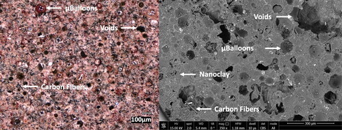
shows images from light microscopy (LM) and scanning electron microscopy (SEM). The LM image shows the phenolic micro-balloons, which reflect light, as well as voids caused by micro- balloon pullout during polishing. The carbon fibers gave rise to black speckles throughout the LM image. The phenolic matrix and the nanoclay are indistinguishable. All of the additives were dispersed with no apparent agglomeration. Because the micro-balloons and the phenolic matrix had the same chemical backbone, they generated identical contrast in the SEM image. This form of microscopy revealed voids caused by trapped air in the printing nozzle. A vacuum mixing apparatus was used to minimize the amount of air trapped in the syringe, since voids generally reduce mechanical performance of composites.
Figure 1. Light microscopy image (left) and SEM image (right) of a printed sample.
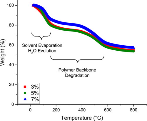
Char yield—the residual mass fraction following pyrolysis—is an important metric for TPS performance and for ablatives, char values are expected to be at least 50 weight % [Citation20]. All three samples exhibited char yield values > 50%, indicating that the formulation will provide acceptable thermal protection. The data from testing is shown in . The char yield measurements of the three samples were consistent and showed little dependence on nanoclay concentration.
Table 1. Char yield values for samples with varying nanoclay concentrations.
The curves used to calculate the char yield values, shown in , revealed three distinct regions. The first region, between room temperature and 200 °C, showed weight loss due to evaporation of solvents. The resol-type phenolic resin contains water as a solvent, which is safer than the more common formaldehyde-based novolac phenolic formulations. In the second region, between 200 °C and 600 °C, the polymer backbone degraded and formed char. Above 600 °C, the weight loss plateaued until 800 °C. also indicated that the weight loss had little dependence on nanoclay content.
Figure 2. Char yield curves of composite samples with various nanoclay contents.
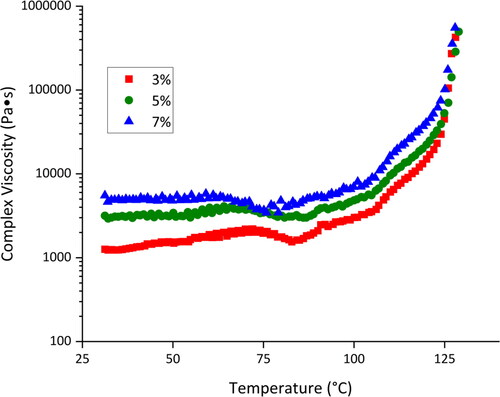
The rheometry experiments showed that the resin viscosity was approximately constant up to ∼ 120 °C, then increased rapidly at higher temperatures (). These viscosity profiles indicated that the resin should be compatible with extrusion printing, without layer slumping. Nanoclay was added to the composite formulation to control viscosity, ensuring printability.
Figure 3. Viscosity as a function of temperature of composite samples.
Gelation temperatures were determined from when the elastic modulus, G’, and storage modulus, G”, were equal [Citation16], and measured values are tabulated in . All of the samples displayed gelation temperatures below room temperature, indicating that the composites will remain malleable until the cure process begins. The resin mixture will not have a potlife since the cure reactions require heat to proceed, leading to increased processing flexibility. Additionally, the increase in gelation temperature with increasing nanoclay content was attributed to steric hindrance by nanoclay particles.
Table 2. The gelation temperatures of different samples with varying nanoclay contents.
The activation energy of resin corresponds to the energy required to polymerize the material and can be used to guide the design of cure cycles. The samples showed consistent values that do not depend on nanoclay concentration. Isothermal rheological tests were completed at 100, 110, and 120 °C. EquationEquation 1(1)
(1) was used to calculate the activation energy, where τgel is the gelation time, R is the universal gas constant, T is temperature, and Ea is the activation energy [Citation16]. The plots generated from these tests (shown in ) allow one to predict the energy required to cure the phenolic resin system, and such plots are useful for designing cure schedules.
(1)
(1)
Figure 4. Arrhenius plot used to calculate the activation energy of the composite polymerization.
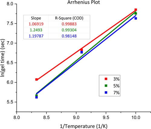
The activation energies of the composites were consistent for the different concentrations of nanoclay. The results, shown in , were consistent with literature values reported by Lee et al. who calculated the activation energies of phenolic resin with varying ratios of phenol to formaldehyde groups [Citation21]. The values of activation energy were low enough to ensure efficient cure of the final TPS with simple and versatile silicone heating blankets.
Table 3. Activation energies of the three different samples containing different amounts of nanoclay.
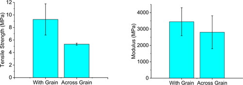
TPS are generally used for heat shields, and thus are not load-bearing components of space vehicles, and thus TPS mechanical properties are not critical. However, investigation of mechanical properties provides insights into process-induced defects, as well as anisotropy arising from the printing process. Thus, samples were sectioned along the printing grain (longitudinal), as well as across the grain, or across the layers (transverse). The samples are referred to as “with grain” and “across grain,” respectively, which will be referred to a longitudinal and transverse. Both types of samples yielded variability in properties, which a finding attributed to defects such as voids resulting from bubbles trapped in the printing syringe, or the general heterogeneity of the composite mixture.
Tensile loading of samples (both orientations) resulted in brittle fracture, as shown in , with different colors representing different samples tested. The phenolic resin matrix fails without notable elongation and no presence of necking, which indicate a brittle material. Longitudinal samples exhibited greater ultimate tensile strength and modulus compared to transverse samples (see ). In this case, anisotropy resulted from the printing process, which produced weaker inter-layer bonding. As one layer was deposited onto the previous one, there was less adhesion between the layers compared to within the extrudate bead.
Figure 5. Stress-strain curves of with grain (left) and across grain (right) samples.
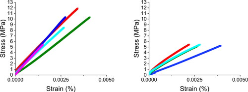
Figure 6. Ultimate tensile strengths and moduli of longitudinal and transverse orientations.
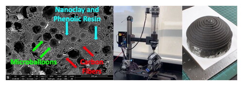
The curved geometry of TPS substrates presents challenges for 3D printing, which generally builds on flat substrates. TPS typically have curved edges that protect the entire perimeter of the vehicle, and these edges cannot be reached by conventional XYZ printer nozzles. For this project, tilt and rotation axes were added to enable the printer to track contoured substrates. Hong et al. demonstrated a method to produce a 5-axis printer through additions to a commercially available printer (Prusa i3 MK3S+) [Citation22]. For this project, mechanical designs were informed by this system and utilized the same controller, with further modification to control the U and V axes (). The further addition included a carriage design using two additional stepper motors to control the additional axes, and a configuration for a replacement controller for the printer.
Figure 7. Printer modification with labeled axis. Arrows indicate positive direction of rotation or movement.
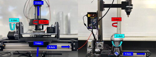
The UV carriage was designed to enable tilt and rotation, with a printing substrate fixed to a rotating disc on a tilting cradle, as shown in . The UV carriage was modified to support the increased weight of the composite material by thickening the carriage walls and curving sharp features in high-stress areas. The design was further modified for the attachment points between the UV carriage and the XY-axis carriage of the surrogate printer (PotterBot 10 Micro). The UV carriage uses two belt-driven stepper motors to manipulate a printing substrate (127 mm diameter). An aluminum hemisphere with a height of 63.5 mm was machined to fit on the substrate to resemble the aluminum back-shell of a space-craft heatshield. shows the seat for the hemisphere fixture, with M5 bolts used to attach the exterior of the dome to the internal heat-set inserts. shows the completed modified printer.
Figure 8. The modified 3D PotterBot 10 Micro printer with 5 axis control.
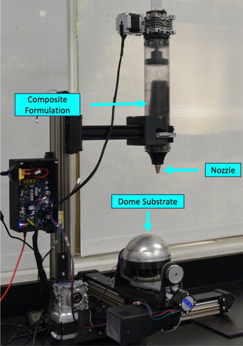
An inexpensive controller was used for the project (Duet3 Mini 5+ with additional expansion board, Duet3 Mini 2+). These boards were used together to drive the six stepper motors required by the system, with five of the motor drivers devoted to the Mini 5+ and one driver to the expansion board. These boards supported the original sensors of the printer with connector modification.
The configuration file of the syringe printer (PotterBot) was rewritten to include the additional axes. Necessary changes included kinematics profile, driver mapping, stepper motor settings, and axis limits. Baseline figures for adding configuration file support of the UV axes provided by Hong et al. were used and expanded upon to refine movements [Citation22]. Communication was established with the controller through USB firmware and file sharing, and control of the printer was established using Wifi on a shared network.
Effort was directed towards producing a hemispherical deposit with shell thicknesses of 3 mm. To accomplish this, a continuous flow was extruded from the nozzle during production at a rate of 150mm3 to produce a minimum layer thickness of 1.5 mm. The flow rate was calculated from EquationEquation 2(2)
(2) . The flow rate was approximate, given the curved surface and adjusted for height variation from the prototype model. The nozzle diameter used for this experiment was 5 mm in diameter and the layer height was approximately 1.5 mm.
(2)
(2)
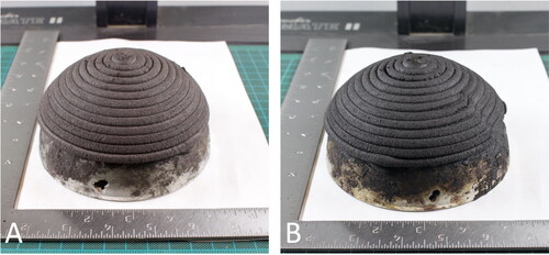
The extrusion pattern consisted of concentric rings ascending the hemisphere surface. The shape was chosen to replicate the geometry of a re-entry heat shield. The G-code for these hemispheres was generated via a custom Python script, allowing for variation in diameter, height, and thickness of the dome. To allow for tolerance within the printed parts of the UV carriage and to resolve any oscillatory movements, a z-axis adjustment script was generated to process the initial G-code. This process is similar to G-code adjustment from bed-leveling in 3d printers, and requires manual mapping of the surface area required as input. In this experiment, the substrate was assessed at every 15 degrees of the V axis while running through a 90-degree rotation of the U axis. The resulting printed part is shown in . A video of the printer extrusion is available in the supplemental information.
Figure 9. Composite dome produced via additive manufacturing from the composite formulation before cure (A) and after cure (B).
4. Conclusions
We have demonstrated a method to produce ablative TPS via additive manufacturing. The method relies on inexpensive commercial components customized to the specific purpose, and a prototype extrudate material designed for compatibility with AM. The composite formulation was suitable for printing, with sufficiently high viscosity to retain the desired geometry during printing balanced by sufficient fluidity for extruding. The measured char yields of the printed and cured product were comparable to ablative materials presently used in TPS for space vehicles. At scale, this method eliminates the need for fabricating and bonding individual tiles to an aluminum back-shell. A multitude of individual tiles no longer needs to be fabricated, reducing production and assembly costs. Deposition of the composite TPS material by AM can be completed entirely in situ, albeit with relatively slow cure rates. The material can also be oven-cured or with heating blankets, affording additional flexibility in production.
A few challenges must be addressed for scale-up. While the printer used here was small and inexpensive, increasing the scale of the printer will require larger and more durable components, including motors, rails, syringe, and carriage system. The amount of material to be extruded (at full scale) will present a challenge, but the resin will not cure without heating, allowing for flexible production timing. Additionally, future work includes arc jet testing to provide data on the time dependent degredation of the printed TPS for comparison with existing systems.
The present work is the first reported TPS advancement that focuses on manufacturing. AM is a potentially feasible method to produce TPS that will potentially reduce cost of production and reduce production constraints. These reductions will make space exploration more accessible, allow more frequent vehicle launches, and spur further advances in material formulations and production methods.
Supplemental Material
Download QuickTime Video (87.8 MB)Acknowledgements
The authors kindly acknowledge funding through NASA Contract 80NSSC21C0604 through a subcontract from Intelligent Optical Systems. The work was undertaken in collaboration with Kyle Brubaker, Eric Kroon, Carl Sepmeyer, Gerardo Ico, and Paul Dicarmine of Intelligent Optical Systems Inc.
Disclosure statement
No potential conflict of interest was reported by the authors.
Data availability statement
The authors confirm that the data associated with the results of this study are available within the article and its supplementary materials.
Additional information
Funding
References
- Glass D. Ceramic Matrix Composite (CMC) Thermal Protection Systems (TPS) and hot structures for hypersonic vehicles. AIAA. 2008; doi: 10.2514/6.2008-2682.
- Venkatapathy E. Ablators - From apollo to future missions to moon, mars and beyond. Inter Astron Congr. 2019.
- Chapline G, Rodriguez A, Snapp C, et al. NASA Engineering Innovations, 182–199.
- Malhan RK, Shembekar AV, Kabir AM, et al. Automated planning for robotic layup of composite prepreg. Rob Comput Integr Manuf. 2021;67:102020. doi: 10.1016/j.rcim.2020.102020.
- Bhatt P, Malhan R, Shembekar A, et al. Expanding capabilities of additive manufacturing through use of robotics technologies: a survey. Addit Manuf. 2019;31:100933. doi: 10.1016/j.addma.2019.100933.
- Graves RA, Witte WG. Flight-test analysis of Apollo heat-shield material using the pacemaker vehicle system (tech. rep.); 1968.
- White T, Hwang H, Ellerby D, et al. thermal protection system materials for sample return missions. Bull AAS. 2021;53(4) doi: 10.3847/25c2cfeb.72d83582.
- Ellerby D, Stackpoole M, Gasch M, et al. Sustaining phenolic impregnated carbon ablator (PICA) for future NASA missions including discovery and new frontiers background-PICA (tech. rep.); 2019.
- Phenolic-Impregnated Carbon Ablator (PICA) Heat Shield Technology is Used by SpaceX - NASA; 2015.
- Venkatapathy E, Ellerby D, Gage P, et al. Entry system technology readiness for ice-giant probe missions. Space Sci Rev. 2020;216(2):22. doi: 10.1007/s11214-020-0638-2.
- Abdullah F, Okuyama K-I, Morimitsu A, et al. Effects of thermal cycle and ultraviolet radiation on 3D printed carbon fiber/polyether ether ketone ablator. Aerospace. 2020;7(7):95. doi: 10.3390/aerospace7070095.
- Kafi A, Wu H, Langston J, et al. Evaluation of additively manufactured ultraperformance polymers to use as thermal protection systems for spacecraft. J Appl Polymer Sci. 2020;137(37) doi: 10.1002/app.49117.
- Roberts T. CSIS Missile Defense Project; 2022.
- Weinzierl M. Space, the Final Economic Frontier. J Econ Perspect. 2018;32(2):173–192. doi: 10.1257/jep.32.2.173.
- Hwang H, et al. Bull. AAS. 2021;53. doi: 10.3847/25C2CFEB.72D83582.
- Sun L. Thermal rheological analysis of cure process of epoxy prepreg [PhD thesis]. Baton Rouge: Louisiana State University; 2002.
- Pulci G, Tirillò J, Marra F, et al. Carbon–phenolic ablative materials for re-entry space vehicles: manufacturing and properties. Composites Part A Appl Sci Manufact. 2010;41(10):1483–1490. doi: 10.1016/j.compositesa.2010.06.010.
- Cho D, Il Yoon B. Microstructural interpretation of the effect of various matrices on the ablation properties of carbon-fiber-reinforced composites. Compos Sci Technol. 2001;61(2):271–280. doi: 10.1016/S0266-3538(00)00212-8.
- Kim HJ, Brunovska Z, Ishida H. Synthesis and thermal characterization of polybenzoxazines based on acetylene-functional monomers. Polymer. 1999;40(23):6565–6573. doi: 10.1016/S0032-3861(99)00046-4.
- Mishra J, Rao C, Bose PSC, et al. Experimental Studies of Resin Systems for Ablative Thermal Protection System. Def Sc J. 2021;71(2):289–295. doi: 10.14429/dsj.71.16252.
- Lee Y-K, Kim D-J, Kim H-J, et al. Activation energy and curing behavior of resol- and novolac-type phenolic resins by differential scanning calorimetry and thermogravimetric analysis. J of Applied Polymer Sci. 2003;89(10):2589–2596. doi: 10.1002/app.12340.
- Hong F, Hodges S, Myant C, et al. Conference on Human Factors in Computing Systems-Proceedings; 2022. doi: 10.1145/3491101.3519782.
Appendix A.
Printer specifications
The following table is a summary of the final printer parameters for the experiment, including values used during the experiment and limits placed by the original or modified equipment.