
Abstract
We propose a novel quasi-distributed sensing system using a wavelength-tunable chaotic fiber laser as well as identical weak fiber Bragg gratings (FBGs). FBG location is determined by measuring the time delay between the reference and the reflected chaotic light. The Bragg wavelength variety of a certain FBG, owing to the influence of external parameters, is scanned by a tunable chaotic fiber laser. The quasi-distributed sensing network is theoretically analyzed. Simulation results reveal hundreds of multiplexing capabilities and a spatial resolution of up to 1.3 cm.
1. Introduction
Quasi-distributed fiber sensing systems based on fiber Bragg grating (FBG) sensors have drawn considerable interest. Compared with electric sensors, FBG sensors have inherent advantages, such as small size, light weight, resistance to electromagnetic interference, and low cost. Quasi-distributed fiber sensing systems have an important function in large civil construction and “Internet of Things,” which has been regarded as a trend in information technology (Han, Zhang, Zhang, & Gu, Citation2010). Fiber laser can obtain higher power, and a chaotic laser can gain a high spatial resolution by using the correlation method. In the quasi-distributed sensing system, all FBGs can be integrated in a single device, thereby reducing costs.
Several fabrication methods of FBG have been developed because of the great value of FBG applications. Identical and weak FBG can be easily written into a single fiber, significantly reducing the production cost of sensors.
Multiplexing capability is a critical issue in the quasi-distributed fiber sensing system. On the basis of the multiplexing capability and demodulation technology, the multiplexing scheme can be distributed into several classes: wavelength-division multiplexing (WDM), time-division multiplexing (TDM), frequency division multiplexing, and their combinations. The multiplexing capability of WDM is limited by the spectral ranges of the source, detector, and wavelength space between two gratings (Abad, Araujo,Ferreira, Santos, & Lopez-Amo, 2003; Wang et al., Citation2012). TDM can markedly increase the number of FBG sensors in the time domain. Recently, Li, Nie, and Song (Citation2012) and Zhang et al. (Citation2012) proposed a fiber sensing system using a low-reflectivity FBG to improve multiplexing capabilities. The pulsed source is used to illuminate the gratings placed at different distances from the source. The main challenges of these sensors are related to the inevitable dead zone (Crunelle, Caucheteur, Wuilpart, & Mégret, Citation2009; Dai, Liu,Leng, Deng, & Asundi, 2009); thus, the spatial resolution is limited to several meters.
This study proposes a novel quasi-distributed optical fiber sensing system based on a chaotic laser as well as identical weak FBGs. The proposed technique can greatly improve the spatial resolution.
2. Principles of the FBG sensing system
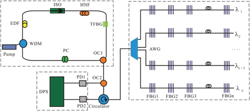
shows the proposed FBG fiber sensing system based on the tunable chaotic fiber laser. The configuration consists of three parts, namely, a wavelength chaotic fiber laser, an FBG sensor array, and a data-processing system (DPS). A tunable fiber grating is installed as a filter in the fiber chaotic laser ring cavity. The laser source is continuous-wave light and wavelength tunable; thus, the laser wavelength is periodically scanning, and reflected light only exists from the corresponding FBG sensor. In the FBG sensor array, the FBGs written in the same line exhibit the same Bragg wavelengths, whereas the FBGs inscribed in different lines exhibit different Bragg wavelengths. FBGs can be identified in both time and wavelength domains.
Figure 1. Proposed FBG sensing system. Pump, 980 nm diode laser; EDF, erbium-doped fiber; ISO, isolator; TFBG, tunable FBG; HNF, high nonlinear fiber; PC, polarization controller; OC, optical coupler; PD, photodetector; DPS, data-processing system; and AWG, arrayed waveguide grating.
The Bragg wavelength in the FBG is given by
where Λ is the grating period and n is the effective refractive index of the fiber core. The shift of the Bragg wavelength in the FBG and the change in strain exhibit a linear relationship within a certain range. is the change in wavelength caused by the change in external parameters.
The chaotic light generated from a chaotic fiber laser is divided into two paths through an optical coupler (OC2). One path enters into the DPS, and the other path launches into the sensing system by an optical circulator. The probe signal travels through the fiber. The proposed interrogation technology is a cross-correlation between the reference signal and the reflected probe signal traveling after many FBGs.
The demodulation principle of this sensing system is illustrated using an FBG array containing five FBGs: FBG1, FBG2, FBG3, FBG4, and FBG5. These five FBGs are identical and weak. If the wavelength of a reference signal is λ, the Bragg wavelength of the five FBGs is also λ ((a1)). If the output function relationship of the reference signal is f(x), the delay between the reflected signal and the reference signal is τ. Consequently, the output function relationship of the reflected signal is f(t−τ). Then, the cross-correlation function is expressed as
Figure 2. Demodulation principle of the proposed system.
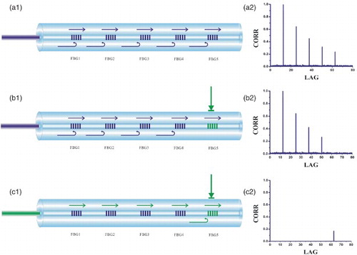
When t=τ1, τ2, τ3, τ4, τ5, five correlation peaks correspond to the five FBGs ((a2)). The FBG location is obtained by determining the time delay τ between the reference light and the reflected light. On the basis of the demodulation principle, the correlation performed by the DPS can obtain the time delay to determine the location of the detection point fiber grating.
The Bragg wavelength changes because of external parameters. If the change in FBG5 wavelength is , and no change is observed in the wavelength of the other four FBGs. The center wavelength of FBG5 is
, whereas that of the other four is λ. Meanwhile, the probe light wavelength is λ ((b1)). A total of four correlation peaks correspond to the first four FBGs. For FBG5, the probe signal is totally transmitted toward the other gratings. No signal returns to the DPS, so no corresponding correlation peak appears ((b2)).
If adjusted to , the wavelength of probe light coincides with the center wavelength of FBG5 ((c1)). The signal returns to the DPS for FBG5, whereas no signal is returned for the first four FBGs. The only correlation peak appearing corresponds to FBG5 ((c2)).
3. Simulations and discussion
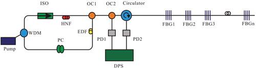
To verify the proposed system, simulation diagram was developed and is shown in . In the erbium-doped fiber ring, chaotic light generates because of the nonlinear Kerr effect. (Henry, Matthew, Michael, & Clifford, Citation1999) The electric field's wave equations is given by
Figure 3. Simulation diagram of the proposed system.
Lx, y contains the linear parts of the propagation operator excluding gain and Nx, y is the Kerr nonlinearity.
The linear operator Lx, y includes the linear birefringence, group velocity dispersion (GVD), and gain dispersion
The nonlinear operators are
3.1 Multiplexibility
Multiplexing capacity is determined by several factors, such as Rayleigh scattering, multi-reflection of optical signals between FBG sensors, fiber transmission loss, and photodetector accuracy.
(1) Case of non-equidistant adjacent FBGs: In this general case, Rayleigh scattering is identified as the main interference. Effective reflected signal can be recognized only if the effective power is higher than the backscattered Rayleigh scatter power. The effective reflected chaotic signal from the FBGn PF is expressed as
According to Personick's backscattering formula, the backscattered Rayleigh scatter power Pb−s is given by
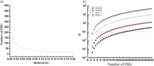
The FBG location can be identified provided that the effective reflected signal is higher than the backscattered Rayleigh scatter. The ratio PF/Pb−s is set to be 10. In the simulation, the transmission loss of the fiber and the Rayleigh scattering coefficient are determined to be 0.16 and 4 dB/km, respectively. The ratio of the backscatter power of Rayleigh scattering, the transmission speed in the fiber, and the pulse lengths are m, and 50 ns, respectively. (a) shows the curve with the relationship between reflectivity and multiplex number. If FBG exhibits a very low reflectivity, hundreds of FBGs can be reached in a single line.
(2) Case of equidistant adjacent FBG: In this case, numerous multi-reflection signals occur between FBGs, and these can interfere with the effective reflected signal (Li et al., Citation2012). To distinguish the signal light and the multi-reflection light, the effective signal light correlation peak should be markedly higher than the correlation peak of the multi-reflection signals.
The cross-correlation function between the reference signal and the effective reflected signal from the Nth FBG is given by
We express the cross-correlation function between the reference signal and the multi-reflection signal affecting the effective reflected signal of the Nth FBG as
A function is defined as follows:
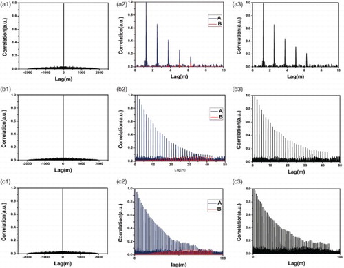
shows our simulation results on a fiber line. Here, three cases are simulated, where their reflectivities of FBGs written in the fiber line are set as 0.2, 0.04 and 0.02, respectively. When the reflectivity is 0.2, the fourth FBG will not be distinguished well, due to the effect of multi-reflections ((a)). With the decrease in the FBG reflectivity, the number of distinguishable FBGs will be enhanced. For example, we can distinguish the 12th and the 20th FBGs when the reflectivities are set as 0.04 ((b)) and 0.02 ((c)), respectively. These results indicate that a lower reflectivity is useful to reduce the effect of multi-reflections.
Figure 4. Rows (a)–(c) depict simulation result at FBG reflection of 0.2, 0.04, and 0.02, respectively. Columns (1)–(3), respectively, show autocorrelation properties of input chaotic light, peak of T(τ) (blue line) and N(τ) (red line), and correlation between all single and input single.
(b) shows the relationship between the number of FBG and ρ at different reflectivities when ρ is set to 10 and FBG exhibits the following values for reflectivity: 0.2, 0.1, 0.04, and 0.02. When the reflectivity is 0.02, the effective FBG number in a single fiber line can reach 20. Hundreds of FBGs can be connected in the system.
Figure 5. (a) Relationship between reflectivity and the effective number of FBG in a single fiber when adjacent FBG is non-equidistant. (b) Relationship between the effective number of FBG in a single fiber and ρ when adjacent FBG is equidistant.
3.2 Spatial resolution
In TDM, the spatial resolution determined by the pulse duration is about tens of meters. The light source in our proposed scheme is a chaotic light. The spatial resolution is determined by the full-width at half-maximum (FWHM) of the correlation peak. In the TDM scheme, the input pulse width is shorter than the round trip time between the two adjacent FBGs to allow the separation of reflected light in the time domain. Thus, the distance of adjacent FBGs is limited. Compared with the TDM scheme, the proposed scheme can obtain a high spatial resolution.
The chaotic bandwidth in this study is defined as the span between the DC and the frequency that has 80% of the energy (Lin & Liu, Citation2003). The Wiener–Khinchin theorem states that spectral density is periodic in the frequency domain. According to the scaling properties of the Fourier transform, a greater frequency range results in smaller FWHM of the delta peak correlation curve. Therefore, a higher spatial resolution can be obtained.
Matlab can be used for sensing simulation. FBGs written in a single-fiber line are used for simulation. Recorded chaotic data from practical measurements are used as probe signals, and the sensing system is simulated. In the model, the spacing between two adjacent gratings is equal, set to 2.5 cm. shows the spatial resolution at different chaotic bandwidths. In (a), the bandwidth of the chaotic sequence is 0.48 GHz (a1). The correlation peaks of the five FBGs cannot be recognized (a2). (b) shows that the bandwidth of the chaotic sequence is 4.8 GHz (b1). Five correlation peaks are easily observed (b2).
Figure 6. Spatial resolution influenced by a chaotic bandwidth.
Columns (1) and (2) show the frequency spectra and the correlation curve, respectively. (a1) and 6(b1) presents the chaotic bandwidths 0.48 and 4.8 GHz.
The greatest chaotic bandwidth obtained is 6.2 GHz ((a)). Under this condition, the distance between adjacent FBGs is narrow. When the adjacent grating spacing is set to 1.3 cm, the spacing of about 6.5 cm is clearly resolved by the five correlation peaks ((b)). A spatial resolution of up to 1.3 cm can be achieved using the correlation method.
Figure 7. (a) The frequency chaotic bandwidth is 6.2 GHz. (b) Correlation trace.
4. Conclusion
We propose and theoretically analyze a quasi-distributed optical fiber sensing network based on tunable chaotic fiber laser as well as identical and weak FBGs. Recorded chaotic data from practical measurements are used as probe signals to simulate the proposed system. Hundreds of multiplexing FBGs are observed, and the spatial resolution is improved to 1.3 cm. FBG sensors are affordable because the generation of a chaotic light requires no external modulation signal source.
REFERENCES
- Abad, S., Araujo, F. M., Ferreira, L. A., Santos, J. L., & Lopez-Amo, M. (2003). Comparative analysis of wavelength-multiplexed photonic-sensor networks using fused biconical WDMS. IEEE Sensors Journal, 3(4), 475–483. doi: 10.1109/JSEN.2003.815806
- Crunelle, C., Caucheteur, C., Wuilpart, M., & Mégret, P. (2009). Original interrogation system for a quasi-distributed FBG-based temperature sensor with fast demodulation technique. Sensors and Actuators A: Physical, 150(2), 192–198. doi: 10.1016/j.sna.2008.11.018
- Dai, Y., Liu, Y., Leng, J., Deng, G., & Asundi, A. (2009). A novel time-division multiplexing fiber Bragg grating sensor interrogator for structural health monitoring. Optics and Lasers in Engineering, 47(11), 1028–1033. doi: 10.1016/j.optlaseng.2009.05.012
- Han, D.-h., Zhang, J., Zhang, Y.-j., & Gu, W.-y. (2010). Convergence of sensor networks/internet of things and power grid information network at aggregation layer power system technology, 2010 International Conference on Power System Technology, Hangzhou, China, pp. 1–6. doi: 10.1109/POWERCON.2010.5666553
- Henry, D, I, A., Matthew, B. K., Michael, B., & Clifford, T. L. (1999). Chaotic dynamics in erbium-doped fiber ring lasers. Physical Review A, 60(3), 2360–2374. doi: 10.1103/PhysRevA.60.2360
- Li, Y.-s., Nie, T.-y., & Song, C.-w. (2012). A proposal of fiber sensing system using low reflectivity FBG. Key Engineering Materials, 500, 743–747. doi: 10.4028/www.scientific.net/KEM.500.743
- Lin, F.-y., & Liu, J.-m. (2003). Nonlinear dynamical characteristics of an optically injected semiconductor laser subject to optoelectronic feedback. Optics Communications, 221(1–3), 173–180. doi: 10.1016/S0030-4018(03)01466-4
- Wang, Y.-m., Gong, J.-m., Dong, B., Wang, D.-y., Shillig, T.J., & Wang, A.-b. (2012). A large serial time-division multiplexed fiber Bragg grating sensor network. Lightwave Technology, 30(17), 2751–2756. doi: 10.1109/JLT.2012.2205897
- Zhang, M.-l., Sun, Q.-z., Wang, Z., Li, X.-l., Liu, H.-r., & Liu, D.-m. (2012). A large capacity sensing network with identical weak fiber Bragg gratings multiplexing. Optics Communications, 285, 3082–3087 doi: 10.1016/j.optcom.2012.02.100