
Abstract
A novel fuzzy adaptive proportional-integral-derivative (PID) control strategy with online set-point tracking is presented for maximum power point tracking (MPPT) in solar photovoltaic (PV) system in this paper. The range of the membership functions of the fuzzy logic for online PID parameter tuner has been optimized using the relay feedback tuning method. The proposed MPPT controller has been designed with online set-point adjustment approach using current, radiation and temperature sensors. Real-time simulations have been carried out on MATLAB™/dSPACE™ ds1104 Research and Development control board platform for solar PV system with synchronous buck converter and resistive load. Performance of the proposed techniques has been compared with main existing MPPT techniques viz. perturb and observe, incremental conductance, fuzzy logic, neural network and adaptive neuro-fuzzy inference system-based methods of MPPT. Performance of various techniques has been compared based on tracking efficiency, steady state and dynamic behaviour. Experimental results showed the superiority of the proposed method for tracking maximum power point under rapidly varying solar radiations.
1. Introduction
Solar energy is a clean, abundant, renewable and freely available source of energy. The major obstacle for the penetration and reach of solar photovoltaic (PV) systems is their low efficiency and high capital cost. The output voltage of the PV system is highly dependent on solar irradiance and panel temperature. The maximum power point tracking (MPPT) system is necessary to ensure maximum power generation. Perturb and observe (PO), incremental conductance (INC), fuzzy logic, neural network (NN), adaptive neuro-fuzzy inference system (ANFIS) and current/voltage feedback-based techniques are few of the many available MPPT methods (CitationSubudhi & Pradhan, 2013). Out of the most widely used MPPT techniques, INC and artificial intelligence-based techniques have higher accuracy but they are complex in design. A PO technique having moderate accuracy is the most extensively used in commercial MPPT systems (CitationEsram & Chapman, 2007). With this approach oscillation is developed around the desired operating point which causes power loss. Compared to PO technique, voltage/current feedback (VF/CF) technique is a simple technique in which the feedback of panel voltage or current is taken and compared with a pre-calculated reference voltage or current; the duty ratio of dc–dc converter is continuously adjusted so that it operates close to that of maximum power point (MPP) (CitationSubudhi & Pradhan, 2013). Due to pre-calculated constant reference voltage/current, it cannot track MPP during changing environmental condition. Proportional-integral-derivative (PID) controller is a widely used control strategy in industrial and process control systems. PID controller tuned by fuzzy logic has been proposed by CitationYang, Ding, and Nan (2011) for MPP tracking which needs power calculation for its operation. CitationHui and Sun (2010) have presented a dual-mode adaptive fuzzy and PID controller using selector switch for output voltage regulation of the boost converter. In the true sense it is not a PV tracking system. In another work proportional-integral (PI) control strategy has been designed by CitationSalhi and Bachtiri (2011) with PV voltage and current sensing for MPP tracking. The PI controller has been designed and simulated with the Bode analysis method using a small signal model of boost converter and tested for the specific values of solar radiation and temperature. In the simulation work carried out by CitationShafy and Nafeh (2011), an MPPT controller has been designed with a modified INC method with a PI regulator with GA-based parameter optimization. In another simulation work (CitationBesheer & Adly, 2012), an ant colony algorithm has been used for PI controller parameter optimization for MPP tracking. Fuzzy gain scheduling of PID with adaptation of scaling factors has been proposed by CitationDounis, Kofinas, Alafodimos, and Tseles (2013) for MPP tracking. The initial values of PID parameters have been determined using the Ziegler and Nichols method and simulations have been carried out, which is supposed to be best suited for linear systems. NN tuned PID-based MPPT approach for duty cycle control of boost converter in a PV system has been found in the simulation work by CitationPark, Cho, and Kim (2012). Fuzzy logic and PID-based MPPT controllers have been simulated by CitationMahammad, Saon, and Chee (2013), but the PID parameter tuning issue has not been addressed. A gradient-descent method has been introduced for PID parameter optimization for MPP tracking in a PV system with single-ended primary inductor converter by CitationKhateb, Rahim, Selvaraj, and Uddin (2013). Optimization of PID parameters can significantly improve the performance of the dc–dc converter minimizing overshoot, settling/rising time and steady-state error. In the aforementioned cases, the PID parameters have been determined offline using various optimizing techniques before initialization of the controller.
Adaptive PID controllers can adjust their parameters automatically in such a way as to compensate for variations in the characteristics of the process they control (CitationStephanopoulos, 1984). This type of controller can be classified based on the way the parameters of the controller are adjusted. The need for online parameter adaptation is due to two reasons. First, for controlling non-linear processes linearized models are used to design linear controllers. Linearized models depend on the particular steady-state (around which the process is linearized) condition and as the desired steady-state operation of the process changes, the ‘best’ values of the controller's parameter change. This implies the need for parameter adaptation. Second, for the non-stationary processes (processes in which characteristics change with time), change in characteristics leads to a deterioration in the performance of the linear controller, thus requiring the adaptation of controller parameters (CitationStephanopoulos, 1984). In the solar PV system the output voltage of the PV panel is highly dependent on solar irradiance and panel temperature. Moreover, the power-voltage and current-voltage characteristics of PV arrays are non-linear in nature. One of the basic components in the PV system is the switch-mode power converter, which ensures the operation of the panel in its maximum generation. Controlling the switched power converters is a challenging area of research in control engineering. A non-linear and non-stationary characteristic of PV system implies the need for an adaptive controller for MPP tracking during varying environmental conditions.
In this paper a novel adaptive PID controller with online parameter adaptation based on fuzzy logic approach and with online set-point adjustment mechanism, without the need for power calculation, has been designed and its real-time implementation has been done on dSPACE™ ds1104 research and development controller board platform. For designing membership functions of the fuzzy logic-based parameter tuner, the relay feedback method has been adopted. The dynamic set-point adjustment mechanism has been designed based on solar radiation and panel temperature values given by radiation and temperature sensors. Performance of the proposed technique has been compared with PO, INC (with proportional-integral regulator), fuzzy logic, NN and ANFIS-based methods of MPPT with reference to the tracking efficiency, steady state and dynamic behaviour.
The paper has been organized as follows: Section 2 gives a brief introduction of solar PV system modelling. In Section 3 mostly referred existing MPPT techniques are described. Design aspects of the proposed MPPT controller are described in Section 4. Real-time implementation of the proposed and existing MPPT techniques on MATLAB™/dSPACE™ platform is described in Section 5. Experimental results and comparison of the proposed and existing MPPT techniques are given in Section 6. The conclusions are discussed in Section 7.
2. Modelling of PV system
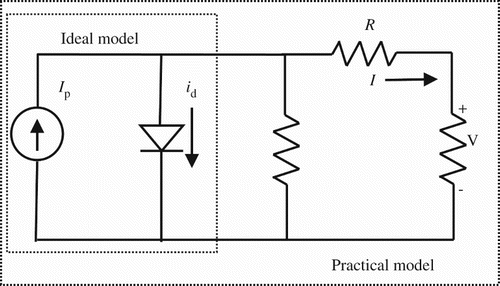
Typically a solar cell can be modelled by a current source with an inverted diode connected in parallel to it as shown in . Series resistance is due to the hindrance in the path of flow of electrons from n to p junction and parallel resistance is due to the leakage current.
Figure 1. Ideal and practical single diode model of a PV cell.
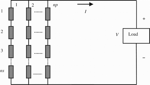
A PV module consists of several PV cells connected in series/parallel. Series connections are responsible for increasing the voltage of the module, whereas the parallel connection is responsible for increasing the current ().
Figure 2. Equivalent circuit of a PV module with series and parallel connected PV cells.
Several PV modules can be interconnected in a parallel-series configuration to form PV arrays. Current–voltage (I−V ) and power–voltage (P−V ) characteristics of a typical solar cell, at a fixed ambient temperature and solar irradiation, are non-linear in nature and shown in .
Figure 3. I−V and P−V characteristics of a solar cell.
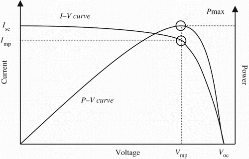
The span of the I−V curve ranges from the short-circuit current (Isc) to open-circuit voltage (Voc). At the ‘knee’ of a normal I−V curve is the MPP (), the point at which the PV cell generates maximum electrical power (CitationMarcelo, Gazoli, & Filho, 2009). The basic mathematical expression of the output current of the PV module () can be expressed as
3. Introduction to MPPT methods
According to the maximum power transfer theorem, an electrical circuit delivers maximum power to the load when source impedance matches the load impedance. In case of a stand-alone solar system, the dc–dc converter is connected in between the PV array and the dc load. The MPPT system varies the duty-ratio of the semiconductor switch in the dc–dc converter in order to match source and load impedance and to deliver maximum power to the load. Various MPPT methods have been reported in the literature. These methods can be classified as (i) methods based on load line adjustment of I−V curve and (ii) methods based on artificial intelligence (fuzzy logic or NN-based MPPT methods). The MPPT methods viz. PO, INC and VF/CF are based on load line adjustment of the I−V curve. These methods have been found to be less suitable under uncertainties due to varying atmospheric and load conditions. The MPPT system based on artificial intelligence (fuzzy logic or NN) has robust capabilities in regard to uncertainties (CitationEsram & Chapman, 2007; CitationSubudhi & Pradhan, 2013). Introduction of various types of MPPT methods has been presented in the following subsections.
3.1. Introduction to the PO MPPT method
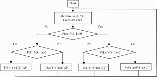
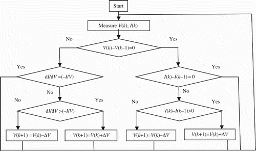
In the PO method PV voltage and PV current are measured using voltage and current sensors and resulting power P1 is calculated. Then introducing small perturbation of voltage Δ V or perturbation of duty-cycle of dc–dc converter Δ D in one direction, corresponding power P2 is calculated. Power P2 is then compared with power P1. If P2 is more than P1, then the perturbation is in the correct direction; otherwise, the direction of the perturbation needs to be reversed. With this approach, the MPP is reached. After this the system will oscillate around the MPP under steady-state condition. These oscillations are responsible for energy loss and hence reduced efficiency. The flowchart of this method is shown in . Although the PO method is simple and mostly used in solar PV systems, the major limitations of this method are deviation from the MPP during rapidly changing environmental conditions. In order to achieve a good steady-state and dynamic response, correct perturbation size is necessary. Small perturbation size leads to a slow tracking performance, while a large size causes large oscillations in steady state (CitationSubudhi & Pradhan, 2013; CitationZhang, Thanapalan, Procter, Carr, & Maddy, 2013).
Figure 4. Flowchart of PO MPPT method.
3.2. INC MPPT method
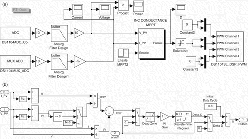
The INC method is based on fact that the slope of the power-voltage curve is zero at MPP (). It is positive in the left and negative in the right as shown in . According to this condition, the MPP can be found in terms of increment of PV array conductance. Equation for the slope
at MPP is given by
Figure 5. Flowchart of INC MPPT method.
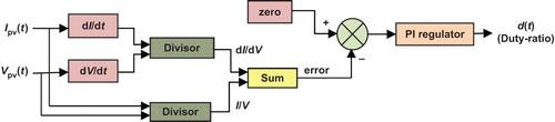
3.3. INC with proportional integral regulator
In the literature we find the modified INC MPPT method with proportional integral (PI) regulator () in order to improve the response of the MPPT, minimizing the error between the actual conductance and INC. The parameter of such a PI compensator can be adjusted/tuned as per system necessity. Also this PI controller can reduce the ripple oscillations in steady state (CitationBrito et al., 2013).
Figure 6. INC MPPT with PI regulator.
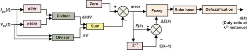
3.4. Fuzzy logic-based MPPT
MPPT methods based on artificial intelligence have become prevalent in recent years as compared to conventional methods because of very good and fast response with no overshoot and less fluctuations under rapid variations in temperature and solar radiation. The fuzzy logic-based MPPT method does not require the exact model of PV system for its design. In most of the literature, a fuzzy logic-based MPPT has been proposed with two inputs and one output. The two input variables are error E(k) and change in error Δ E(k), given by CitationAlgazar, Monier, Halim, and Salem (2012):
Figure 7. Fuzzy logic-based scheme for MPP tracking.
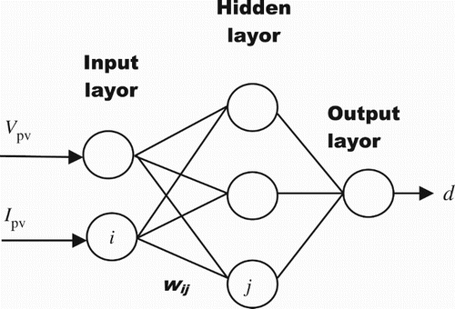
3.5. NN-based MPPT method
The NN-based MPPT technique operates like a black box model and does not require detailed information about the PV system (CitationHiyama & Kitabayashi, 1997). Block diagram of the NN-based MPPT method is shown in . The link between ith and jth node has weight wij. The inputs can be PV voltage, PV current and/or environmental data such as solar radiation and temperature or a combination of all/any of these. Output of the NN is the duty cycle used to operate the dc–dc converter at MPP. The input data to train the network can be obtained from experimental measurement- or model-based simulation results. NN can track the MPP after training it with the input data (CitationBahgat, Helwa, Ahmad, & Shenawy, 2005; CitationVeerachary & Yadaiah, 2000).
Figure 8. NN-based MPPT technique.
3.6. ANFIS-based MPPT
An ANFIS integrates NN and fuzzy logic. Fuzzy logic has the capability to transform the linguistic terms into numerical values using fuzzy rules and membership functions. However finding the correct fuzzy rules and membership functions which highly rely on the system behaviour can become a challenging task. NN is a powerful technique for mapping the non-linear functions but it works as a black box model. An ANFIS combines NN and fuzzy logic to overcome drawbacks of the individual techniques (Iqbali, Abu-Rub, & Ahmed, Citation2010). A properly tuned ANFIS-based MPPT system can track MPP with higher accuracy than the PO method (CitationAldobhani & John, 2008).
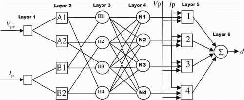
Layer 1 is the input layer; neurons in this layer pass the external crisp input signal to layer 2. Layer 2 is the fuzzification layer; neurons in this layer perform fuzzification. Layer 3 is the rule layer; each neuron in this layer corresponds to a fuzzy rule. A rule neuron receives input from the respective fuzzification neurons and calculates the firing strength of the rule it represents. Layer 4 is the normalization layer; each neuron in this layer receives inputs from all neurons in the rule layer and calculates the normalized firing strength of a given rule. Layer 5 is the defuzzification layer; each neuron in this layer is connected to the respective normalization neuron and also receives input signals to calculate weighted consequent value of a given rule. Layer 6 is represented by a single summation neuron and it calculates the sum of outputs of all defuzzification neurons and produces the overall ANFIS output. The ANFIS based MPPT controller scheme has been shown in .
Figure 9. ANFIS-based MPPT scheme.
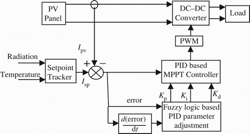
4. Proposed fuzzy adaptive PID-based MPPT controller
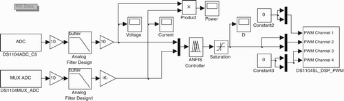
The proposed fuzzy adaptive PID-based MPPT Control technique includes a dynamic set-point tracking approach based on actual radiation and temperature, while online PID parameter (proportional gain Kp, integral constant Ki and derivative constant Kd) adjustment has been accomplished using a fuzzy logic approach. The range of output membership functions (i.e. maximum limits of Kp, Ki and Kd) has been optimized using the relay feedback method. The block diagram of the proposed approach has been shown in .
Figure 10. Block diagram of proposed control schemes for MPPT.
4.1. Design of set-point tracker
A dynamic set-point tracking assures the dynamic operating point of the proposed controllers of current at MPP (Imp). The proposed controllers for MPP tracking have been designed based on the following relation between Isc and Imp:
4.2. Design of PID controller
A PID controller combines proportional, integral and derivative modes to calculate the output based on error between a measured variable and a desired set point as represented in the Laplace domain Equation (18):
4.3. Design of fuzzy parameter tuner
The fuzzy logic-based control approach has less dependence on the mathematical model of the process to be controlled and hence there is no need to develop an accurate process model. Also the fuzzy logic controller can handle process non-linearities (CitationPanda, Pathak, & Srivastava, 2011). The proposed fuzzy parameter tuner has been designed with two inputs (viz. error and rate of change of error) and three outputs (viz. change in proportional gain , change in integral constant Δ Ki and change in derivative constant
). The two input variables can be expressed as
where Ipv is the output current of PV module and Isp is the estimated (using set-point tracker) PV current at MPP for the measured solar radiation and module temperature. Triangular membership functions with seven fuzzy sets (VVL, VL, L, M, H, VH and VVH) have been assigned for two input and three output variables (refer (a)–(e)). The rule base is given in . The Mamdani method of fuzzification and centroid method of defuzzification are used for real-time implementation of the fuzzy algorithm. Structure of the fuzzy parameter tuner is given in . The response of the fuzzy tuner for typical values of error and rate of change in error is given in . Error, e(k), and the rate of change in error, Δ e(k), have been divided into seven fuzzy sets, viz. very very low (VVL), very low (VL), low (L), medium (M), high (H), very high (VH) and very very high (VVH). Similarly, output variables (, Δ Ki and
can be divided into seven fuzzy sets. The corrected values of the PID parameters can be obtained from the following equations:
Figure 11. (a) Membership function of input variable – error, (b) Membership function of input variable – rate of change of error, (c) Membership function of output variable – Kp, (d) Membership function of output variable – Ki and (e) Membership function of output variable – Kd.
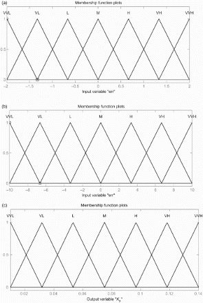
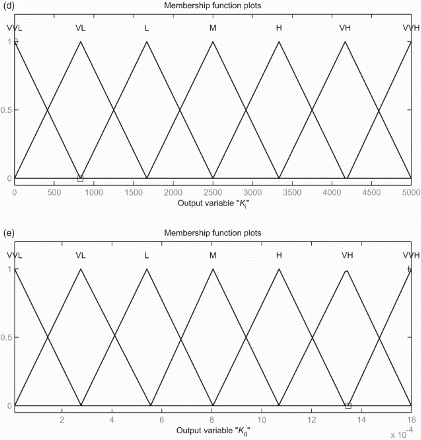
Figure 12. Structure of fuzzy tuner.
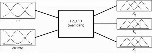
Figure 13. Response of fuzzy tuner for typical inputs.
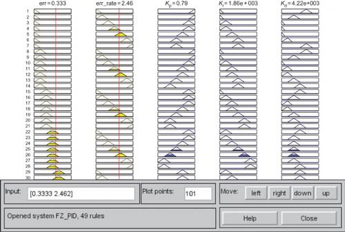
Table 1. Rule base for input and output membership functions.
4.4. Relay feedback-based PID parameter tuning
Relay-based autotuning is a simple way to tune PID controllers for non-linear systems as compared to other existing methods. It avoids trial and error, and minimizes the possibility of operating the process close to the stability limit (CitationWilson, 2005). A DC–DC converter is supposed to be one of the traditional benchmark problems of non-linear control. In the present work, a synchronous buck converter has been used due to its higher efficiency as compared to a conventional (asynchronous) buck converter (CitationJain, 2013). The basic configurations of the solar system with asynchronous and synchronous buck converters are shown in (a) and 14(b), respectively.
Figure 14. (a) and (b) Configuration of asynchronous buck converter in solar PV system.
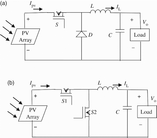
In the asynchronous buck regulator, the output voltage is controlled by changing the duty-ratio of the semiconductor switch S. When the switch is on, the diode D is reverse biased, the inductor and the load get energy from the input solar energy. During off state of the switch, the diode becomes forward biased and the output stage receives the energy from the inductor and the input remains isolated. The net energy transferred to the output from the input is always lesser than that of the input in a given switching cycle. The ratio of output to input voltage is given by (CitationRashid, 2001)
Table 2. Buck converter parameters.
From the buck converter point of view, the control scheme shown in can be supposed to be of the feed-forward type. In such a case input-to-output steady-state relation needed for feed-forward controller design. Hence in order to design the controller line (input voltage of buck converter) to output (output voltage of buck converter), small signal transfer function given in Equation (22) has been considered (CitationErickson & Macsimovic, 2001). The small signal transfer function (Gvg) that relate the output voltage with the variation of the input (line) voltage with variations in duty ratio set to zero is given by
Figure 15. Relay tuning method.
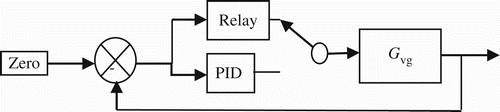
Table 3. PID parameters.
For the parameters of buck converter mentioned in , is found to be
5. Real-time implementation of proposed and existing MPPT techniques
5.1. Hardware details
A poly-crystalline solar PV module (Vikram Solar ELV37) of specifications mentioned in , with a synchronous buck converter, has been used for experimental analysis of the proposed and existing MPPT techniques.
Table 4. PV module parameters at standard test conditions.
MPPT algorithms have been designed in MATLAB™/ SIMULINK™ and implemented using dSPACE™ ds1104 R&D controller board. Design specifications and the parameters of the synchronous buck converter are mentioned in . The synchronous buck converter has been designed using IRF540N (with milli Ohm) as a high-side MOSFET and IRFZ44N (with
milli Ohm) as a low-side MOSFET. The driving circuit for these MOSFETs has been designed using IR2110. For the proposed MPPT algorithm current, radiation and temperature sensors are needed, while for other algorithms voltage and current sensors are required to be interfaced with computer system via ds1104 controller board. Also radiation and temperature sensors are needed for calculation of theoretical maximum power. Voltage, current, radiation and temperature sensors have been designed and calibrated for implementation of various MPPT algorithms.
Voltage sensor is designed using a voltage divider resistive network (Rp and Rv) as shown in . Output voltage is sufficiently reduced by adjusting the value of the variable resistor. As per the specifications of the ds1104 controller board, it accepts analogue input in the range of ±10 Volt. Hardware interfacing of four sensor inputs and one output (duty ratio) with personal computer with dSPACE™ds1104 R&D controller board, MATLAB™, SIMULINK™ and CONTROLDESK™ software is shown in .
Figure 16. Hardware interfacing of using dSPACE™ R&D board.
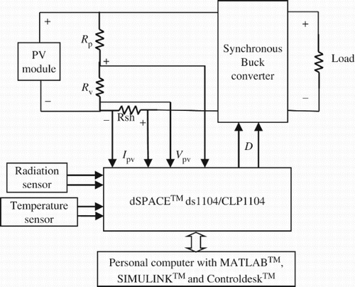
Current measurement has been done using a low value (0.01 Ohm) shunt resistor (Rsh) that will output a voltage proportional to the current flowing through it. Since the shunt resistor is non-isolated, caution must be exercised with its placement. For direct current measurement, the shunt resistor needs to be placed as close to the neutral as possible to avoid errors. In the absence of the neutral point, a proper signal conditioning circuit has to be used.
A reference solar module is used for the measurement of the solar radiation. Proper calibration should be done to match the technology of the reference module with the technology of the PV module used (CitationInternational Energy Agency, 2003).
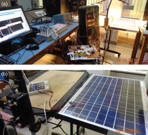
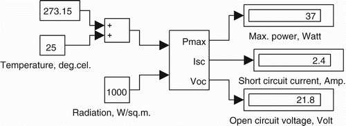
In the present work pre-calibrated reference module and LM35 temperature sensor have been used to estimate the theoretical MPP. Extensive calibration measure has been performed on the PV module and reference module. The average intensity of the solar radiation striking on the PV module was calculated by measuring the radiation level at various points on the PV panel. According to this value, the output of the radiation sensor was calibrated. For measurement of module temperature LM35 temperature sensor is used which gives 10 mV change across output voltage per degree Celsius change in the input temperature (). Two Zener diodes with a breakdown voltage of 10 V and a resistor of 10 K Ohm are arranged to protect the ds1104 A/D converter from overvoltage. The photo snap of experimental set-up and calibration of radiation sensor using reference PV module is given in (a) and 18(b).
Figure 17. Configuration of temperature sensor.
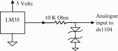
Figure 18. (a) Experimental set-up for real-time implementation of MPPT algorithms and (b) radiation and temperature sensors used for real-time simulations.
5.2. Performance indices of MPPT system
The choice of the MPPT technique for a specific application is an important design factor and should be based on the efficiency of the MPP tracker, response time, peak overshoot, static and dynamic error, sensors needed and implementation complexity. All these parameters of the MPPT system have been analysed in the present work in order to compare the various MPP tracking techniques. Efficiency is the most important parameter of an MPPT algorithm and can be calculated as
Figure 19. Subsystem for calculation of theoretical maximum power.
The influence of MPPT on the PV system depends on static performance – how closely it operates to a fixed MPP and its dynamic performance – how well it responds to changes in MPP. Accuracy (static and dynamic) indicates how close to MPP the MPPT operates the PV system and can be defined as a percentage of or Pmax (CitationJantsch et al., 1997),
In the present work all the MPPT control algorithms have been programmed with MATLAB™ and implemented using the dSPACE™ ds1104 R&D controller board and CLP1104 connecter and LED panel. Four channels of analogue data input and one channel of PWM output channel have been used to interface four sensors (voltage, current, radiation and temperature sensors) and one output signal (duty-ratio). The dSPACE™ system samples and converts the sensor outputs to digital signals, processes them as per programme in MATLAB™ and then outputs the pulse-width-modulated (PWM) signal to the driving circuit of the synchronous buck converter via the PWM output channel. As per the specifications of the dSPACE™ for analogue input in the range −10 V to +10 V, the SIMULINK™ output is in the range −1 V to +1 V. Hence proper gains for input and output signals need to be chosen.
5.3. Modelling and real-time simulation of MPPT algorithms
MATLAB™/SIMULINK™ models of various MPPT algorithms have developed and laboratory-based real-time simulations have been carried out for comparing proposed and existing algorithms based on their responses for step change in the solar irradiation. Step change in the solar radiation of the two similar halogen lamps was introduced using toggle switches.
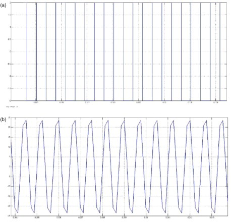
The model for implementing fuzzy adaptive PID-based MPPT algorithm is given in (a)–(c). The optimal values of PID parameters found using relay tuning method have been used to design membership functions of output variables of the fuzzy tuner. PV current Ipv is all the time compared with current at maximum power Imp value of which is determined based on solar radiation and panel temperature. One of the PWM channels of the ds1104 is used to output the 120 KHz pulses whose duty ratio is adjusted by the MPPT controller. A model for relay tuning is given in , while relay output and process response is given in (a) and 22(b), respectively. Using Equations (26), (23) and , critical gain () and critical time (
s) have been found out and then optimal PID parameters have been determined (
,
and
). Based on these parameters the range of membership functions of output variables of fuzzy tuner has been decided.
Figure 20. Model of the proposed MPPT controller.
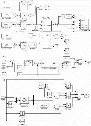
Figure 21. Model for determination of PID parameters using relay method.
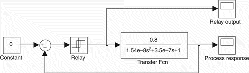
Figure 22. (a) Relay output and (b) process output.
The model of the PO MPPT is given in , with initial value of the duty ratio of 0.8. The model for the INC MPPT with discrete PI controller is shown in (a) and 24(b).
Figure 23. Model for PO MPPT controller.
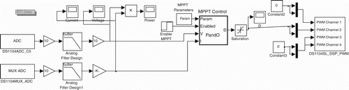
Figure 24. Model of incremental conductance MPPT controller.
A fuzzy-based MPPT system has been designed using two input variables (CitationKartika, Rathika, & Devaraj, 2013) viz. and rate of change of
(
), given by
Figure 25. Model of fuzzy logic based MPPT controller.
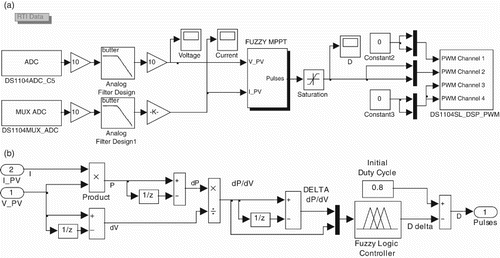
Figure 26. Input output membership functions.
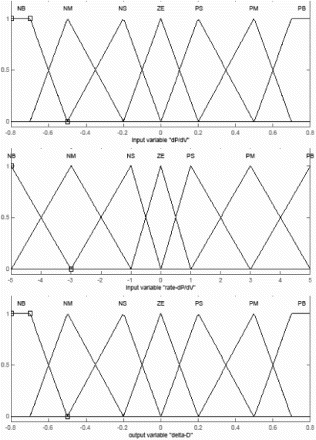
Table 5. Rule base for fuzzy MPPT system.
The Mamdani method of fuzzification and centroid method of defuzzification are used for real-time implementation of the fuzzy MPPT algorithm.
The NN-based MPPT controller is modelled as shown in (a) and 27(b). Two-layer feed-forward NN with 10 sigmoid hidden neurons is designed with nntool of MATLAB™. The network has been trained with an experimental set of input data using Levenberg–Marquardt back-propagation algorithm. A total of 7609 samples were collected from real-time system out of which 5327 samples (70%) were used to train the network, while the remaining samples were used for validation and testing purpose. The mean square error (MSE) and regression of the NN model developed are given in . Mean squared error is the avarage squared difference between outputs and targets, while regression gives the correlation between outputs and targets. A value of regression equal to 1 refers to a close relationship, while 0 is for random relationships.
Figure 27. Model of neural network based MPPT controller.
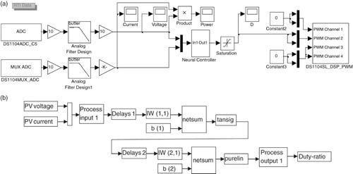
Table 6. MSE and regression values of training, validation and testing process.
In the present work the ANFIS controller has been developed with two inputs and one output (). In this controller fuzzy rule base has been generated based on Sugeno inference model. For a fair comparison between fuzzy and ANFIS-based MPPT approaches, structure of the input and output membership functions has been designed as per . The data for training are also same as that of the NN-based MPPT design. The anfisedit tool of MATLAB™ has been used to design the ANFIS controller with two neurons in layer 1 and 14 neurons in the fuzzification layer.
Figure 28. Model of ANFIS based MPPT controller.
6. Results and discussions
Response of various existing MPPT algorithms along with the proposed algorithm has been shown in (a)–(h). Variation in measured power with respect to step change in input solar radiation intensity has been plotted along with calculated maximum power. The theoretical value of maximum power has been determined based on the radiation and temperature sensor outputs. As duration of real-time simulations is less than a minute, almost no effect of panel temperature on calculated power has been observed. Performance of the PO MPPT method was analysed with three different fixed perturbation sizes (Δ D=0.1, 0.01 and 0.001). It can be seen from the responses that the steady-state oscillations have been reduced and efficiency has been increased with decrease in Δ D and satisfactory response can be achieved with , but overall MPPT efficiency is limited to around 84%. Real-time simulations have been carried out for 4–5 times under different atmospheric conditions and lower and higher values of the efficiency obtained by using various MPPT techniques have been mentioned in . The INC (with PI regulator) method of MPPT exhibits very little steady-state oscillations and steady-state error is lesser as compared to that of PO MPPT, response to abrupt change in the input radiation. It can be seen that the dynamic response has also been improved as compared to the PO MPPT.
Figure 29. (a) Response of PO MPPT with Δ D=0.1, (b) response of PO MPPT with Δ D=0.01, (c) response of PO MPPT with Δ D=0.001, (d) response of INC with PI regulator (INC-PI) MPPT, (e) response of fuzzy logic-based MPPT, (f) response of NN-based MPPT, (g) response of ANFIS-based MPPT and (h) response of proposed fuzzy adaptive PID-based MPPT.
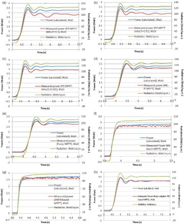
Table 7. Comparison of proposed and existing MPPT algorithms.
The fuzzy logic-based MPPT technique resulted in about 90% efficiency with lower steady-state error as compared to the INC PI technique of MPPT. Other artificial intelligence-based techniques offered higher efficiency as mentioned in . Oscillatory response has been observed during steady-state MPPT in the case of NN and ANFIS-based MPPT techniques, which is due to resolution issue. Although the ANFIS MPPT method resulted in higher efficiency, it offered much higher overshoot along with steady-state oscillations. All the MPPT techniques mentioned earlier use voltage and current sensors for their working, and calculation of power is essential for MPP tracking in most of these techniques.
The proposed fuzzy adaptive PID-based MPPT technique offered much better efficiency with very little overshoot and good steady-state and dynamic response. The effect of change in sampling time of data acquisition has also been analysed. It is seen that for larger sampling frequency the steady-state error has been greatly reduced. Performance comparison of proposed and existing MPPT techniques () has been carried out based on tracking efficiency, sensed parameters, circuit complexity and the necessity of tuning.
7. Conclusions
A new fuzzy adaptive PID-based optimal MPP tracking approach has been proposed to improve the performance of PV system. A fuzzy adaptive PID-based MPPT controller with dynamic set-point tracking approach has been designed using PV current, solar radiation and panel temperature sensors. Real-time simulations of proposed and conventional MPPT algorithms have been carried out for performance comparison and validation. The experimental results show that the proposed approach can achieve better efficiency as compared to PO, INC (with PI regulator), fuzzy logic, NN or ANFIS-based MPPT techniques under rapidly changing solar radiations. Although the proposed approach needs three sensors, it does not require calculation of PV power as in the case of other conventional methods. Future work includes experimental implementation of the proposed method for grid connected solar PV system with multilevel inverter.
REFERENCES
- Aldobhani, A. M. S., & John, R. (2008). MPPT of PV system using ANFIS prediction and fuzzy logic tracking. Proceedings of int. multi-conf. of engg. and comp. sci, Hong Kong.
- Algazar, M. M., Monier, H., Halim, H., & Salem, M. (2012). Maximum power point tracking using fuzzy logic control. Elsevere Journal on Electrical Power and Energy Systems, 39, 21–28. doi: 10.1016/j.ijepes.2011.12.006
- Bahgat, A. B. G., Helwa, N. H., Ahmad, G. E., & Shenawy, E. T. E. (2005). MPPT controller for PV systems using neural networks. Renewable Energy, 30(8), 1257–1268. doi: 10.1016/j.renene.2004.09.011
- Besheer, A. H., & Adly, M. (2012). Ant colony system based pi maximum power point tracking for stand alone photovoltaic system. In Proceedings of IEEE international conference on industrial technology (pp. 693–698). Athens, Greece.
- Brito, M., Galotto, L., Sampaio, L., Melo, G., & Canesin, C. (2013, March). Evaluation of the main MPPT techniques for photovoltaic applications. IEEE Transactions on Industrial Electronics, 60(3), 1156–1167. doi: 10.1109/TIE.2012.2198036
- Dounis, A. I., Kofinas, P., Alafodimos, C., & Tseles, D. (2013, December). Adaptive fuzzy gain scheduling PID controller for maximum power point tracking of photovoltaic system. Renewable Energy, 60, 202–214. doi: 10.1016/j.renene.2013.04.014
- Dyk, V. (2002). Long-term monitoring of photovoltaic devices. Renewable Energy, 22, 183–197.
- Erickson, R.W., & Macsimovic, D. (2001). Fundamentals of power electronics (2nd ed., pp. 464–471). New York, NY: Kluwer Academic.
- Esram, T., & Chapman, P. (2007). Comparison of photovoltaic array maximum power point tracking techniques. IEEE Transactions on Energy Conversion, 22, 439–449. doi: 10.1109/TEC.2006.874230
- Green, M. A. (1992). PV modules-operating principles, technology and system applications. Kensington, Australia: Prentice-Hall.
- Hiyama, T., & Kitabayashi, K. (1997). Neural network based estimation of maximum power generation from PV module using environment information. IEEE Transactions on Energy Conversion, 12(3), 241–247. doi: 10.1109/60.629709
- Hui, J., & Sun, X. (2010). MPPT strategy of PV system based on adaptive fuzzy PID algorithm. In Proceedings of international conference on intelligent computing for sustainable energy and environment (pp. 220–228). Wuxi, China.
- International Energy Agency. (2003). Guidelines for monitoring stand-alone photo-voltaic power systems (Report: IEA PVPS T3, pp. 18–22).
- Iqbal, A., Rub, H. A., & Ahmed, S. M. (2010). Adaptive neuro-fuzzy inference system based maximum power point tracking of a solar PV module. In Proceedings of IEEE international energy conference (pp. 51–56).
- Jain, A. (2013). Synchronous vs asynchronous buck regulators (pp. 1–5). Camarillo, CA: Semtech Corp. Retrieved August 2013, from url: http://www.digikey.com/Web%20Export/Supplier%20Content/Semtech_600/PDF/Semtech_synchronous-vs-asynchronous-buck-regulators.pdf?redirected=1
- Jantsch, M., Real, M., Haberlin, H., Whitaker, C., Kurokawa, K., Blasser, G., & Kremer, P. (1997). Measurement of PV maximum power point tracking performance. Proceedings of photovolt. solar energ. Conf, Barcelona.
- Kartika, S., Rathika, P., & Devaraj, D. (2013). Fuzzy logic based maximum power point tracking designed for 10 Kw solar photovoltaic system. International Journal of Computer Science and Management Research, 2, 4121–1427.
- Khateb, A. E., Rahim, N. A., Selvaraj, J., & Uddin, M. N. (2013). Maximum power point tracking of single-ended primary-inductor converter employing a novel optimisation technique for proportional-integral-derivative controller. The Institution of Engineering and Technology Journal on Power Electronics, 6(6), 1111–1121.
- Kumari, J. S., Babu, S., & Yugandhar, J. (2011). Design and investigation of short circuit current based maximum power point tracking for photovoltaic system. Science Academy Publisher International Journal of Research and Reviews in Electrical and Computer Engineering, 2, 63–68.
- Liptak, B. (2006). Instrument engineer's handbook: Process optimization and control (4th ed., pp. 117–119). Boca Raton, FL: ISA-CRC Publication.
- Luis, C., & Sivestre, S. (2002). Modelling photovoltaic systems using PSpice. Chichester: John Wiley & Sons Ltd.
- Mahammad, A. K., Saon, S., & Chee, W. S. (2013). Development of optimum controller based on MPPT for photovoltaic system during shading condition. In Proceedings of Malaysian technical universities conference on engineering & technology (Vol. 53, pp. 337–346). Retrieved from url: http://www.sciencedirect.com/science/article/pii/S187770581300163X
- Marcelo, M. G., Gazoli, J., & Filho, E. (2009). Comprehensive approach to modeling and simulation of photovoltaic arrays. IEEE Transactions on Power Electronics, 24, 1198–1208.
- Panda, A., Pathak, M. K., & Srivastava, S. P. (2011). Fuzzy intelligent controller for the maximum power point tracking of a photovoltaic module at varying atmospheric conditions. Journal of Energy Technologies and Policy, 1(2), 18–27.
- Park, J., Cho, H., & Kim, D. (2012). Neural PID based MPPT algorithm for photovoltaic generator system. New & Renewable Energy, 8(3), 14–22. doi: 10.7849/ksnre.2012.8.3.014
- Rashid, M. (2001). Power electronics handbook (pp. 213–214). New York, NY: Academic Press.
- Salhi, M., & Bachtiri, R. (2011, June). A maximum power point tracking photovoltaic system using a proportional integral regulator. Science Academy Transactions on Renewable Energy Systems Engineering and Technology, 1(2), 37–44.
- Shafy, A., & Nafeh, A. (2011). A modified MPPT control loop for PV/battery-charging system using PI controller optimally tuned with GA. International Journal of Numerical Modelling: Electronic Networks, Devices and Fields, 24, 111–122. doi: 10.1002/jnm.764
- Stephanopoulos, G. (1984). Chemical process control, an introduction to theory and practice (pp. 431–432). Englewood cliff, NJ: PHI.
- Subudhi, B., & Pradhan, R. (2013). A comparative study on maximum power point tracking techniques for photovoltaic power systems. IEEE Transactions on Sustainable Energy, 4, 89–98. doi: 10.1109/TSTE.2012.2202294
- Veerachary, M., & Yadaiah, N. (2000). ANN based maximum power tracking for PV supplied dc motors. Solar Energy, 69(4), 343–350. doi: 10.1016/S0038-092X(00)00085-2
- Wilson, D. I. (2005, March). Relay-based PID tuning. Automation & Control, 10–12, New Zeland.
- Yang, W., Ding, L., & Nan, L. (2011). The application of fuzzy parameters self-tuning PID controller in MPPT of photovoltaic power system. In Proceedings of IEEE conference on transport., mech. and elect. engg. (pp. 1129–1132). Changchun, Jilin.
- Zhang, F., Thanapalan, K., Procter, A., Carr, S., & Maddy, J. (2013, June). Adaptive hybrid maximum power point tracking method for a photovoltaic system. IEEE Transactions on Energy Conversion, 28(2), 353–360. doi: 10.1109/TEC.2013.2255292
- Zhou, W., Yang, H., & Fang, Z. (2007). A novel model for photovoltaic array performance prediction. Journal of Applied Energy, 84, 1187–1198. doi: 10.1016/j.apenergy.2007.04.006