
 ?Mathematical formulae have been encoded as MathML and are displayed in this HTML version using MathJax in order to improve their display. Uncheck the box to turn MathJax off. This feature requires Javascript. Click on a formula to zoom.
ABSTRACT
The purpose of this paper is to provide a robust solution for fault detection in the induction motor. The structure of nonlinear unknown input observer is investigated for observer design in this paper. Recently, rotor defect is considered as the most important non-electric fault in induction motors. One of the challenges in rotor fault detection is the uncertainty in the mechanical load of the motor and the harmonics in the electric power. Accordingly, these cases are considered as disturbances for unknown input observer and their effects on the residual signal are eliminated. The results of the simulation show the performance of the observer to diagnose the induction motor rotor fault in different scenarios.
1. Introduction
Induction motors are used as the most common variable speed drives in small and large-scale industries. In fact, the induction motor is the major drive of industry, and its speed is frequently controlled electronically. High reliability, high efficiency, and proper operation of these motors have resulted in their widespread application. Operation of the motors under faults can disturb their performance and also reduce their life span. Therefore, diagnosis of the faults can improve the performance and increase the life time of the motors (Bonnett & Soukup, Citation1992).
The most important benefit of fault diagnosis is that it can almost predict the damaging time of the motor by the analysis of the parameters variations; Fault diagnosis in electrical machines can be used to detect incipient faults, and this leads to fast unscheduled corrective maintenance, short downtimes and elimination of harmful side-effects (Henao et al., Citation2014). Hence, diagnosis method is an important part of the management, expert and artificial intelligent systems (Thomson, Citation1998; Jiahui, Hongli, Fei, Nan, & Xuerong, Citation2017; Xianye, Hongli, Fei, & Gongfa, Citation2018).
In the recent past, fault detection and tolerance of the induction motor has been the focus of attention of researcher community. For a good insight, the interested reader is referred to (Isermann, Citation2011; Khan & Ding, Citation2011).
In such cases, many types of faults should be taken into account (e.g. broken rotor bars or interterm faults, to name a few) and relatively long detection times can be permitted. On the other hand, if the aim of the fault detection is to apply any of the fault-tolerant techniques detailed in (Gonzalez-Prieto, Duran, Barrero, Bermudez, & Guzmán, Citation2017; Mohammadpour & Parsa, Citation2015; Guzman et al., Citation2016), the fault detection times should be as short as possible.
The most important innovation of the paper is the design of an unknown input observer using the LMI concept to overcome the uncertainty and disturbances effects in a particular class of nonlinear systems that the faulty induction motor is in this class. So, the robust unknown input observer for nonlinear induction motor is considered. A robust unknown input observer is derived for nonlinear systems having both disturbances and uncertainties. The observer derivation is carried out based on the LMI approach. Then the observer design problem is extended for a kind of nonlinear system whose nonlinear function satisfies Lipschitz condition. The novelty of the proposed observers lies in the fact that these can handle both disturbances and uncertainties. The effectiveness of the proposed observers are demonstrated using three numerical examples. The results show that the proposed observers are capable to detect the induction motor fault.
The rest of the paper is organized as follows: Brief introduction of induction motor and model of system is given in Section 2. Robust unknown input observer design approach has been presented in Section 3. Observer Design for fault detection in the induction motor rotor is given in Section 4. In Section 5, the numerical results are presented to verify the performances of the observer. Finally, a conclusion is drawn in Section 6.
2. Dynamic model of induction motor
In this section, the dynamic equations of the induction motor are presented for using in the observer design. In general, the dynamical equations of the motor depend on the choice of reference. In this paper, a synchronous rotational reference is used for dynamical modelling of an induction motor. The reason for this choice is that the dq (direct-quadrature axis) variables remain constant in the steady state in synchronous rotation reference. Obviously, this reduces design complexity of unknown input observer. Overall, the dynamic equations of the motor can be considered as (1). In this regard, other equations are defined as follows:
(1)
(1)
(2)
(2)
(3)
(3)
(4)
(4)
(5)
(5)
(6)
(6) In the above equations,
and
are stator currents in the dq reference,
and
are stator magnetic fluxes in the dq reference,
is the mechanical angular speed and
is the synchronous speed,
is number of pole pairs,
is stator resistance,
is rotor resistance,
is stator inductance,
is rotor inductance and
is induction inductance.
Based on the dynamic equations of the induction motor, it is clear that the motor dynamic has non-linear complex terms and cannot be used to identify the defect in the induction motor rotor. The purpose of the paper is to provide a solution based on a non-linear uncertain input observer for defect detection. Accordingly, the description of the nonlinear unknown input observer is explained below, and then its design is provided to identify the rotor defect.
3. Nonlinear unknown input observer
This section provides a new method to design a nonlinear unknown input observer for detecting a defect in induction motor rotor. Based on the explanations given in the previous section, the dynamics of the induction motor can be determined as Equations (7)–(8). In these relations, is the state vector,
is the input vector,
is the output vector,
is fault vector,
is the disturbance vector,
is nonlinearity term, the matrices
,
,
,
,
of suitable dimensions are known and
,
are the uncertainties of the matrices A and B respectively. In (7), it is assumed that the
satisfies Lipschitz condition. In these relations,
is a Lipschitz constant and
is arbitrary matrix for satisfying the equation. It is obvious that due to the derivability of induction motor dynamics, it is possible to establish relations (9) and (10) for this system.
(7)
(7)
(8)
(8)
(9)
(9)
(10)
(10) Lemma 1 (Khania & Haeri, Citation2015): If
is a definite positive matrix and symmetric and x (t) is arbitrary, then the relation (11) is true.
(11)
(11) The purpose of the unknown input observer design, its stability is guaranteed in the presence of uncertainty and load variations in the induction motor. In order to design unknown input observer, the structure of the observer should be specified initially. The nonlinear structure used in this paper is shown in Equations (12) and (13). In the above mentioned relations,
,
,
,
and
matrices are observer parameters with suitable dimensions,
is estimate of
and z (t) is the state vector of the observer. In general, the parameters of the observer must be chosen in such way to guarantee the stability condition for the observer.
(12)
(12)
(13)
(13) The following is how the parameters of the observer are calculated. By defining the estimation error based on Equation (14) and the conditions based on (17) to (19), the estimation error dynamics can be considered as (20). It should be noticed that the conditions (17) to (19) are considered to meet the requirements of the observer design, including the insensitivity of the residual signal to disturbance.
By defining the error as follows:
(14)
(14) The dynamic equation of the error is obtained as follows:
(15)
(15) where
(16)
(16) Now, by choosing Equations (17)–(19) as follows, the dynamic equation of the error is simplified as (20).
(17)
(17)
(18)
(18)
(19)
(19)
(20)
(20)
Theorem: An unknown input observer is stable if, by choosing the appropriate matrices ,
and
, the error Equation (21) to be established. In this equation,
(21)
(21) Proof: Consider the equation of (22) as Lyapunov function. In order to prove the stability of the mentioned observer, Equation (23) must be satisfied for all states. By deriving of the Lyapunov function (22) and Equation (20), we can obtain (24).
(22)
(22)
(23)
(23)
(24)
(24) By considering (9), Lemma 1 and introduced approach in (Sharifuddin, Ch, & Kingshook, Citation2010), we can write (25) from Equation (24).
(25)
(25) Now by considering Equation (25), Equation (26) can be obtained.
(26)
(26) In Equation (26),
. Then the proof ends. Until now, the proposed structure of the nonlinear unknown input observer for defect detection has been studied for a certain class of nonlinear systems. It also proved by the Lyapunov theorem. The purpose of the next section is observer design to detect the fault of the induction motor rotor.
So, with the proper selection of control parameters, including the matrices and
, and also the choice of the initial starting point in the absorption region, Equation (21) is feasible (Imani, Jahed-Motlagh, Salahshoor, Ramezani, & Moarefianpur, Citation2017; Taleb Ziabari, Jahed-Motlagh, Salahshoor, Ramezani, & Moarefianpur, Citation2017).
4. Observer design for fault detection in the induction motor rotor
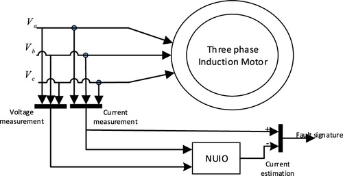
The purpose of this section is detecting the rotor's defect in induction motors by using of the proposed observer in the paper. The overall schematic of the proposed method is shown in Figure .
Figure 1. Schematic of the proposed method for detecting the rotor fault in the induction motor.
4.1. Modelling of rotor fault
The first step in the design of the observer for detecting the fault is the proper modelling of the rotor fault in the induction motor and its effect on its dynamics. In general, the rotor fault of the squirrel cage can be considered as two broken rotor bars and broken end-rings. In this paper, the breakage of the rotor bar is considered for the design and evaluation of the observer (Zandi & Poshtan, Citation2017).
The mentioned rotor fault increases the rotor's equivalent resistance. That is because the number of parallel bars have reduced at the rotor surface. Therefore, the resistance of the rotor in the presence of defect can be considered based on (27). In this equation, is the nominal resistance of the rotor,
is the value of the rotor's resistance due to the broken rotor bar. In this equation,
is the resistance of a rotor bar, N is the number of bars and n is the number of broken bars.
(27)
(27)
(28)
(28) According to (6), it is clear that with the variation of the rotor resistance, the coefficients α, λ change in the dynamical model of the induction motor. This will change the dynamics of induction motor, which will be explained below.
4.2. An unknown input observer design
In order to design an unknown input observer to detect the induction motor rotor fault, the dynamic equations must first be written consistent with Equations (29) and (30). Based on Equations (1)–(6) A, B, C matrices and nonlinear function can be written as
(29)
(29)
(30)
(30)
(31)
(31)
(32)
(32)
(33)
(33)
(34)
(34) Based on the previous section explanations and (27), the rotor fault affects the four state variables of the induction motor. Therefore,
and
can be considered as
(35)
(35)
(36)
(36)
In this paper, the load variation is considered as mechanical disturbance. Therefore, its effect on the output of the observer (the residual signal) should be minimized. According to the given descriptions, and
is as follows:
(37)
(37)
4.3. Fault diagnosis
The most important issue in the design of the observer and fault detection is residual signal definition. In this paper, an unknown non-linear input observer used to estimate the induction motor stator current. Accordingly, the residual signal of the proposed algorithm can be considered as Equation (38). In this equation, and
are the stator currents in the dq reference and
,
are estimates of the stator current in the mentioned reference. Also, the method of fault detection in the proposed algorithm is based on Equation (39). In this equation,
is a threshold based on the parameter uncertainties of the induction motor and its applied voltage.
(38)
(38)
(39)
(39)
5. Simulation results
In previous section, the design of an unknown input observer for fault detection in an induction motor had investigated. The purpose of this section is to evaluate the proposed observer in various scenarios using MATLAB software. The developed fault detection system is tested with 2.2-kW induction motor. The analyzed cases include different motor conditions with and without broken rotor bars. The method is based on the residual signal of induction motor in healthy and faulty cases. The residual signal has to be followed by residual evaluation in order to arrive at a detection decision. In some cases the residuals never become zero because of the presence of noise and model errors, even if there is no fault. The nominal parameters of the induction motor used in this paper are based on Table . To better detection of the induction motor rotor fault, the produced residual signal is passed through a discrete butterworth filter with 5 Hz cutoff frequency.
Table 1. Nominal Parameters of the induction motor.
Also, the solution of the LMIs for the observer gain matrix is as follows:
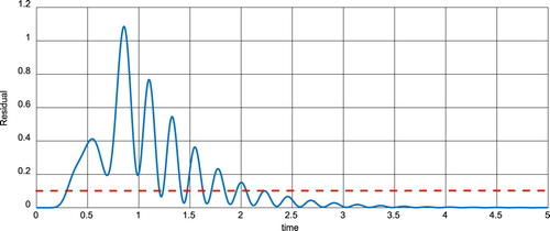
5.1. First scenario
In this scenario, there is no fault for the induction motor rotor. In other words, the motor is considered in the nominal state. It is also assumed that there is no load on motor. How to change the residual signal is shown in Figure . Clearly, after transients, the amount of the residual signal remains to some extent lower than the threshold. It should be noticed that the threshold value will be obtained on the basis of a statistical method.
Figure 2. Residual signal in the first scenario.
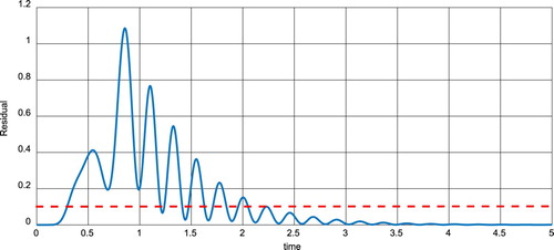
5.2. The second scenario
In this scenario, there is no fault for the induction motor rotor. In other words, the motor is considered in the nominal state. It is also assumed that the nominal load value changes from 0 N.m to 10 N.m at t = 3s. How to change the residual signal is shown in Figure . Clearly, after passing the transients, the amount of the residual signal remains to some extent lower than the threshold. Of course, the insensitivity of the observer structure to the load variation is considered at design time. This scenario demonstrates the correctness of the observer design process.
Figure 3. The residual signal in the second scenario.
5.3. The third scenario
In this scenario, it is assumed that in t = 3s, one of the rotor's bars is broken. Other motor parameters are in the nominal mode. It is also assumed that the nominal load value changes from 0 N.m to 10 N.m at t = 2s. How to change the residual signal is shown in Figure . Clearly, by breaking one of the rotor's bars, the residual signal remains higher than the threshold and the fault of rotor bar is detected.
Figure 4. The residual signal in the third scenario.
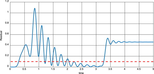
These figures demonstrate the accuracy of the developed fault detection system. Consequently, for the broken rotor bar diagnosis, we established a criterion which it is able to detect the occurrence of fault for an induction motor in different working conditions.
6. Conclusion
In this paper, an unknown nonlinear observer for detecting fault was presented for a specific class of nonlinear systems. Its stability was also proved by the Lyapunov theorem. In the following, it used to detect the rotor fault of the induction motor. In design, load variations were considered as disturbances for observer. Therefore, their effects on the residual signal were removed. Finally, the results of simulation were shown in different scenarios and the performance of the observer was verified.
Disclosure statement
No potential conflict of interest was reported by the authors.
Correction Statement
This article has been republished with minor changes. These changes do not impact the academic content of the article.
References
- Bonnett, A. H., & Soukup, G. C. (1992). Cause and analysis of stator and rotor failures in three-phase squirrel-cage induction motors. IEEE Transactions on Industry Applications, 28, 921–937. doi: 10.1109/28.148460
- Gonzalez-Prieto, H. G. I., Duran, M. J., Barrero, F., Bermudez, M., & Guzmán, H. (2017). Impact of post-fault flux adaptation on six-phase induction motor drives with parallel converters. IEEE Transactions on Power Electronics, 32, 515–528. doi: 10.1109/TPEL.2016.2533719
- Guzman, H., Duran, M., Barrero, F., Zarri, L., Bogado, B., Gonzalez-Prieto, I., & Arahal, M. (2016). Comparative Study of Predictive and Resonant Controllers in fault-tolerant Five-phase induction motor drives. IEEE Transactions on Industrial Electronics, 63, 606–617. doi: 10.1109/TIE.2015.2418732
- Henao, H., Capolino, G., Fernandez-Cabanas, M., Filippetti, F., Bruzzese, C., Strangas, E., … Hedayati-Kia, S. (2014). Trends in fault diagnosis for Electrical machines: A Review of Diagnostic techniques. IEEE Industrial Electronics Magazine, 8, 31–42. doi: 10.1109/MIE.2013.2287651
- Imani, H., Jahed-Motlagh, M. R., Salahshoor, K., Ramezani, A., & Moarefianpur, A. (2017). A novel tube model predictive control for surge instability in compressor system including piping acoustic. Cogent Engineering, 4(1). doi: 10.1080/23311916.2017.1409373
- Isermann, R. (2011). Fault diagnosis Applications: Model based condition Monitoring, Actuators, drives, Machinery, Plants, Sensors, and fault-tolerant systems. Berlin, Germany: Springer Verlag.
- Jiahui, L., Hongli, D., Fei, H., Nan, H., & & Xuerong, L. (2017). Filter design, fault estimation and reliable control for networked time-varying systems: A survey. Systems Science & Control Engineering, 5(1), 331–341. doi: 10.1080/21642583.2017.1355760
- Khan, A., & Ding, S. (2011). Threshold computation for fault detection in a class of discrete-time nonlinear systems. International Journal of Adaptive Control and Signal Processing, 25, 407–429. doi: 10.1002/acs.1205
- Khania, F., & Haeri, M. (2015). Smooth switching in a scheduled robust model predictive controller. Journal of Process Control, 31, 55–63. doi: 10.1016/j.jprocont.2015.04.003
- Mohammadpour, A., & Parsa, L. (2015). Global fault-tolerant control technique for multi-phase permanent-magnet machines. IEEE Transactions on Industry Applications, 51, 178–186. doi: 10.1109/TIA.2014.2326084
- Sharifuddin, M., Ch, G., & Kingshook, B. (2010). LMI approach to robust unknown input observer design for Continuous systems with noise and uncertainties. International Journal of Control, Automation and Systems, 8, 210–219. doi: 10.1007/s12555-010-0205-9
- Taleb Ziabari, M., Jahed-Motlagh, M. R., Salahshoor, K., Ramezani, A., & Moarefianpur, A. (2017). Robust adaptive control of surge instability in constant speed centrifugal compressors using tube-MPC. Cogent Engineering, 4(1). doi: 10.1080/23311916.2017.1339335
- Thomson, W. T. (1998). On-line current monitoring and application of a finite element method to predict the level of static airgap eccentricity in three-phase induction motors. IEEE Transactions on Energy Conversion, 13, 347–357. doi: 10.1109/60.736320
- Xianye, B., Hongli, D., Fei, H., & Gongfa, L. (2018). Event-triggered distributed filtering over sensor networks with deception attacks and partial measurements. International Journal of General Systems, 47(5), 522–534. doi: 10.1080/03081079.2018.1462353
- Zandi, O., & Poshtan, J. (2017). Broken-bar rotor fault detection in squirrel-cage induction motors at presence of sensor faults using adaptive Unscented kalman filter. In 5th International Conference on control, Instrumentation, and Automation (ICCIA) (pp. 296–300). Shiraz. doi: 10.1109/ICCIAutom.2017.8258696