
 ?Mathematical formulae have been encoded as MathML and are displayed in this HTML version using MathJax in order to improve their display. Uncheck the box to turn MathJax off. This feature requires Javascript. Click on a formula to zoom.
Abstract
In the proposed approach, an Extended Model Predictive Sliding Mode Controller (EMPSMC) is designed to control Three-Level Ac/Dc Power Converters to achieve improved dynamic performance and better. Steady-state stability. The traditional proportional-integral (PI) controller is used in the Model Predictive PI controller (MPPIC) technique to produce active power reference. However, this technique results in a significant overshoot/undershoot and steady-state error. Instead of PI, sliding mode control (SMC) is used to overcome these shortcomings. The performances of EMPSMC and MPPIC are compared and analyzed with and without disturbance. The results show that the system’s settling time is minimized by introducing SMC, and the overshoot is also reduced. Moreover, it also provided better steady-state stability. Similarly, dynamic improvements are achieved with EMPSMC for tracking the desired dc reference voltage demand. The simulation results validate the performance of the designed model.
Nomenclature
| Symbols | = | Description |
| Vga, Vgb, and Vgc | = | grid input voltages of phase a, b, and c |
| iga, igb, and igc | = | grid input current of phase a, b, and c |
| Vca, Vcb, and Vcc | = | converter input voltages of phase a, b, and c |
| Vdc | = | output voltage across load resistor |
| RL, iL | = | load resistor, load current |
| Sk | = | switching state of each phase where k =a, b, and c |
| = | switching state, input voltage of | |
| Ts | = | sampling time. |
| P, Q | = | active, reactive powers of the system |
| Qref, Pref | = | references of active, reactive power |
| = | Cost function | |
| = | Tracking error, instantaneous dc voltage, desired dc voltage level | |
| = | bound on the uncertainty of disturbance, is controller gain, sigmoid function |
Introduction
Motivation and Incitement
Due to its wide-range industrial applications in power systems, a three-phase AC/DC Power converter has recently attained significant attention (Zhang, Sun, et al., Citation2013). The power converter has versatile capabilities and usages, for example, controllable power factor, power flow direction control, line current harmonic minimization, and better voltage regulation. Hence, it is used in a wide range of areas like renewable generation resources (photovoltaic, wind, and biomass.) (Liu & Chen, Citation2015), microgrid technology (Davari & Mohamed, Citation2013) railway electrification systems (Antonio, Citation2014) and high voltage DC systems (Venkataramanan & Johnson, Citation2003) Various control techniques have been researched and applied to effectively and efficiently control power converters, e.g. model predictive control (MPC), a direct power control (DPC), and voltage-oriented control (VOC). The VOC has outstanding steady-state tracking capability and fast dynamic response. The traditional VOC contained a dual looped construction, the outer loop acts as a voltage control system, and the inner loop acts as a current control system. However, the existing loop and proportional-integral (PI) limitations are significantly dependent on the converter’s dynamic performance (Zhang, Sun, et al., Citation2013; Kadri et al., Citation2011)
Literature review
Currently, MPC based techniques have been proposed for power converters to improve system performance (Bordons & Montero, Citation2015) There are several benefits of the MPC technique as compared to the traditional controllers; for example, it optimizes the current state while considering future states (Kwak & Park, Citation2015) good tracking and steady-state stability, modulation free, can be easily fit into the algorithm, and have a faster response against disturbances and uncertainties. On the other hand, during the simulation process, the PI controller parameters remain fixed, limiting its dynamic performance, particularly during disturbances and uncertain circumstances. In the case of MPPIC, to satisfy the system’s requirement, it is impossible to discover a single conventional PI control parameter as long as the system changes its states; this is mainly due to its limitation of constant stimulation parameters. Another controller, the SMC (sliding mode controller), exhibits excellent dynamic performance. Moreover, SMC also has an excellent tracking ability for unbalanced loads, linear, and non-linear disturbances (Raeispour et al., Citation2020a; Li, Citation2016)
Because of its stability and robustness against inner and external disturbances, SMC has found many modern power systems and renewable energy control (Li, Citation2016) In (Baghaee et al., Citation2018) a robust SMC control scheme has been proposed to improve stability and power-sharing for non-linear and linear loads. Moreover, the authors also proposed separate controllers for positive and negative sequences. A robust sliding mode with mixed H2/H∞ is proposed for AC microgrids (Baghaee et al., Citation2017) Two different controllers are used together for inner and outer loop current. Adaptive backstepping integral nonsingular fast terminal sliding mode control (ABINFTSMC) technique also reject the disturbance and ensure stability.
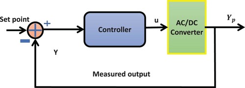
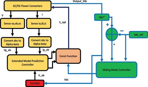
The proposed approach is based on an extended model predictive sliding mode control (MPSMC). The drawbacks of the conventional PI controller with MPPIC are tackled by replacing it with the SMC. Firstly, the necessary AC/DC power converter, MPC, and SMC are analyzed theoretically for in-depth understanding. In the next step, sampling time, active and reactive power is computed using the predicted value of the grid current, which results in improved computational time. We designed a control law and sliding surface for dc-voltage regulation of the power converter’s active and reactive power by considering this feature. Finally, the simulation is carried out to witness a dynamic presentation that will be obtained from the proposed scheme. A basic MPSMC based system model is shown in Figure . To regulate the active and reactive power asymptotically, the pulse-width-modulation (PWM) technique is used in the rotational frame (do coordinate) of the power converter’s model. The classical VOC method is used to track their position (Kadri et al., Citation2011) The harmonics created by the PWM techniques are mostly at the Power-converter’s output side; however, input current and power ripples can also be introduced (Shireen et al., Citation2006) (Dannehl et al., Citation2009) Another two loops, i.e. inner current, and outer voltage are also considered, with PI controllers due to their simple anatomy. However, this approach’s downside is its performance, strongly dependent on the current loop and the PI controller’s parameters (Zhang, Sun, et al., Citation2013) Moreover, the PI controller’s fixed parameters limitation also minimizes its stability and dynamic performance under disturbances. Another approach is based on the DPC technique that does not require an inner current loop and PWM for regulating both powers (Cho & Lee, Citation2016) This task is performed by a switching table, which is very difficult to create and more prone to large ripples. Because of this strong dependency of the DPC technique on a very accurate switching table, the steady-state stability can be strongly affected, which is undesirable. Another controller, sliding mode control (SMC), with prominently better steady-state stability and dynamic performance than PI, is adopted to resolve this limitation. SMC is an excellent responsive controller with strong robustness against disturbances and uncertainties of a dynamic system (Cho & Lee, Citation2016; Knight et al., Citation2006) In this technique, a control signal is used to direct the system’s trajectory to slide along a surface identified as the sliding surface. The system points’ trajectories are forced to the neighbourhood of this surface and then are moved towards the equilibrium point (Cao & Fei, Citation2016) Moreover, this controller has outstanding capabilities under uncertainties to keep the controller adjustable on the sliding surface (Sebaaly et al., Citation2016)
Figure 1. System general diagram.
Contribution and paper structure
This paper’s fundamental objective is to form a hybrid control technique by combining SMC and EMPC (EMPSMC) to counterbalance the traditional PI-based MPC systems’ drawbacks. The EMPSMC technique is also adopted for better tracking of an active power position and for enhancing the following characteristics:
Dynamic presentation of the system
Elevated overshoot or undershoot issue
Robustness
Extended settling time, and
Increased steady-state error during a disturbance
The remaining paper is organized as: the analytical modelling of the proposed approach is discussed in section II. Section III is regarding the modelling of EMPSMC. Section IV presents the proposed approach, section V is about simulation results, and section VI concludes this paper.
System description and analytical modelling
The circuit of a three-level Ac-Dc power converter consisting of six metal-oxide-semiconductor-field-effect transistors (MOSFET) switches, as shown in Figure .
Figure 2. Three-level AC/DC converter.
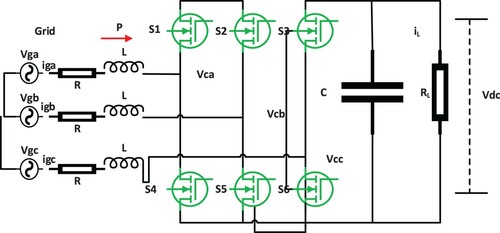
The three-phase system is connected with these switches though RL filters have the same resistance and inductance values. The output voltage harmonics on the Dc side are filtered using a capacitor filter C. Equation 1 & 2 represents the mathematical model of the three-phase power converter. Note that as the spectrum of the closed-loop matrix includes simple repeatedλeigenvalues, the spectrum of
includes
simple repeated zero eigenvalues. Hence, we may say
(1)
(1)
(2)
(2) Vga, Vgb, and Vgc and three-phase input voltages and iga, igb, and igc are respected currents of phases a, b and c. The converter input voltages are Vca, Vcb, and Vcc; Vdc is the output voltage across load resistor RL and iL is the corresponding load current.
(3)
(3) where Sk is the switching state of each phase k. For instance, if Sa=1;
Based on Clarke transformation, three-phase switching states can be transformed into two phases as;
(4)
(4)
Where is the switching matrix. Based on this matrix, the two-phase input voltage can be represented as;
(5)
(5) The three-phase input voltage can be represented on the two phases
in the form of eight vectors by using the space vector pulse width modulation (SVPWM) scheme, as shown in Figure .
Figure 3. Voltage vectors representation using the Clarke transformation (αβ coordinate system).
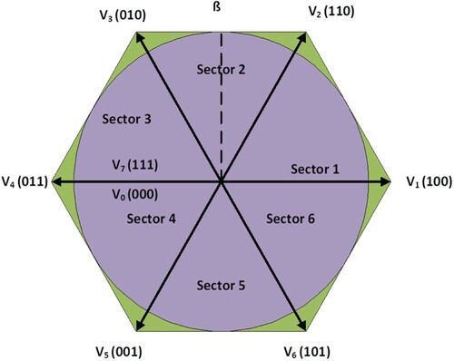
The two voltage vectors V0 and V7 are zero, respectively. Based on this representation, the two-phase model can be represented as follows;
(6)
(6)
Modelling of EMPSMC control strategy
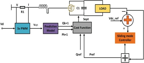
In the MPPIC controller-based approach, the traditional PI controller is adopted to uphold the output voltage reference. However, the PI controller’s limitation is that it has fixed parameters set, and the system’s dynamic performance becomes undesirable and slow when the system’s demand or parameters are variable. To resolve this limitation, SMC, which has prominently better steady-state stability and dynamic performance than PI, is adopted in the proposed approach, as shown in Figure .
Figure 4. The system Block diagram of EMPSMC scheme.
The discrete-time model of power converter at the (n+1)th sample can be expressed as;
(7)
(7) Where Ts is the sampling time. Then, the active (P) and reactive (Q) powers of the system are calculated as:
(8)
(8)
By considering P and Q, the cost function is expressed as;
(9)
(9) The Qref and Pref are the references of active and reactive power, and the function
is used to find the optimal space vector for the upcoming switching step with a minimal value of cost function.
The proposed control EMPSMC
The primary control problem is to derive a proper control law to track the desired dc voltage level. The instantaneous power can be expressed in terms of dc voltage as;
(10)
(10)
Figure 5. The system Algorithm of EMPSMC Scheme.
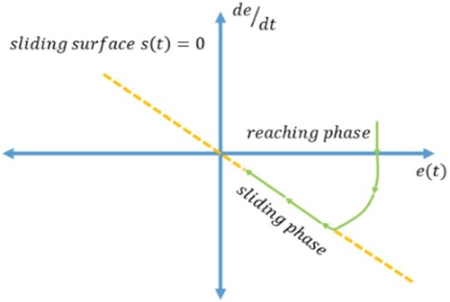
The position vectors are required to reach and slide on this surface to minimize the error, as shown in Figure . where is, the excellent time constant. The derivative of equation (12) can be expressed as (Figure );
Figure 6. Trajectory Plot like any sliding action into SMC.
Based on the sliding surface model, the control law U in terms of instantaneous power can be expressed as;
(13)
(13)
From the above analysis, controller design is expressed as;
(14)
(14) Where
is bound on the uncertainty of disturbance,
is controller gain, and
is the sigmoid function.
Proof of existence condition
All the trajectory points in a sliding surface designed should be reached within a specified time *31. To guarantee this, the following criteria should be satisfied.
(15)
(15) Substituting (13) and (14) (11) result in:
(16)
(16) By multiplying the SV by (16), one finds the state of existence of sliding mode. Therefore, the existing condition of sliding mode is satisfied with the following two cases (Zhang, Sun, et al., Citation2013)
Case 1: If the access point is in a positive state, create a switching surface neighbourhood field, i.e.
then
(17)
(17) This leads to
(18)
(18) Case 2: If the access point is in an unfavourable position, created switching surface neighbourhood field,
i.e.
then,
(19)
(19) This results in
(20)
(20) From (18) and (20), one can conclude that the state of existence can be satisfied by choosing the appropriate sliding coefficients,
and
.
Proof of the tracking condition
Sliding mode tracking can be obtained using the Lyapunov stability analysis (Zhang, Sun, et al., Citation2013) (He et al., Citation2018) For those analyses, the Lyapunov function is as:
(21)
(21) This is positive for any point of completion, the expected equilibrium point being
Only when the sliding variable reached the equilibrium point, the Lyapunov function
will be zero. Therefore, the Lyapunov function
is positive. Based on (18) and (20),
can be obtained as
(22)
(22) The derivative
is negative.
Theorem: If the Lyapunov function is positive and its derivative is negative, the system is precisely stable at the equilibrium point.
As a result, the designed Lyapunov function complies with the robustness of Lyapunov stability analysis. Furthermore, the equilibrium point can be expressed as:
(23)
(23) Substituting (14) into (11) reveals that when the system trajectory points reach the sliding surface, i.e. SV = 0, the uncertainty disturbance is equal to zero as well, i.e. δ = 0. Then, the first-order derivative of the voltage error concerning time can be rewritten as:
(24)
(24) According to (24), as long as the sliding coefficient λ is positive, the trajectory points can remain stable at the sliding surface theoretically. However, as the ac/dc converter is a non-linear system, a positive λ can hardly guarantee that all the reaching points satisfy the stability condition, except for those points from the stability field’s vicinity. By applying the MPC and SMC schemes simultaneously in this system, all the trajectory points can remain stable at the designed sliding surface only when λ is chosen from an inherent range of the analysed set, i.e. λ > 0.
Based on the above analysis, the non-linear quality to select the switching state should be as follows.
If,
therefore, choose a switching state suitable to decrease
If,
If,
Results & discussion
In this section, the tracking performance of the proposed scheme is evaluated. Moreover, the output response is also compared with the MPPIC scheme to track performance without disturbance.
Simulation results
The simulation parameters of the Ac/Dc power converter are given below Table .
Table 1. Parameter of converter.
Figure shows the steady-state response of the dc-link voltage; Vdc is the output on the Dc side of the power converter. The dynamic response of the EMPSMC is also much better and fast than the convention MPPIC technique, as can be seen in Table and 3.
Figure 7. The output response of Step Response of EMPSMC schemes.
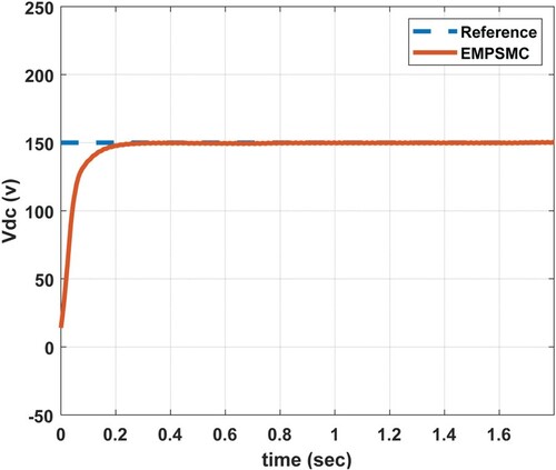
Table 2. Dynamic performance evaluation of EMPSMC and MMPIC
The EMPSMC model’s performance is further compared with the already developed model for three-phase Ac/Dc power Converter, presented in (More et al., Citation2015) In (More et al., Citation2015) a robust MPSMC controller is presented, tracking performance for the step input is very good. Our designed model’s accuracy and efficiency are presented in Tables and by considering systems’ dynamics parameters.
Table 3. System dynamic performance evaluation.
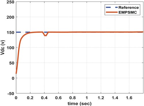
To evaluate the proposed model’s performance, a measured disturbance of 10 V is added to the system from t=0.4 sec to 0.43 sec.
The proposed controller’s response is very fast, and the output reference rapidly attains the actual position. Overall, the EMPSMC based system’s performance is very smooth and responsive with a rise time of 0.1087 s, and the undershoot of the system is 1.0967%. Figure shows the disturbance rejection capability of the system. It can be observed that the output response shows a little deviation due to the added disturbance.
Figure 8. The Output response of the system with EMPSMC plus interference (Disturbance).
However, to further justify the proposed system’s superiority, its tracking performance is compared with the MPPIC based system.
To validate the proposed controller’s real-time performance capabilities, the end-users load demand first increased and decreased during the simulation process. Figure (a). shows the response of the proposed approach to an unpredicted rise in the load. At t=1 sec demand is stepped up from 150 to 200 V. The proposed EMPSMC took 0.0401 sec to match new load demand with very little error.
Figure 9. Output reaction to an unpredicted of dc voltage load demand increase (a) demand load increase (b) demand load decrease.
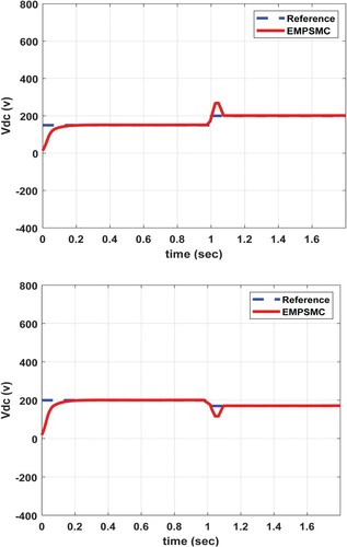
Moreover, EMPSMC forces the dc voltage value to the new desired reference with almost very low/less overshoot. Figure (a) shows the active power dynamic response is much faster and reaches the steady-state value of 300 W. Figure (a) shows the response of grid current to the variation, an increase in the grid current can be observed due to the increase in the load.
Figure 10. Output reaction to an unpredicted of dc voltage load demand increase (a) Active power increase (b) Active power decrease.
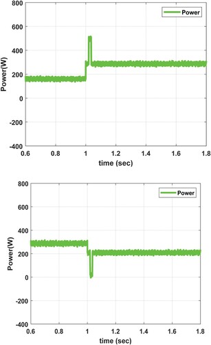
Figure 11. Output reaction to an unpredicted of dc voltage load demand increase (c) Phase A voltage and current increase (d) Phase A voltage and current decreases under EMPSMC.
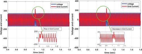
Furthermore, another response of the proposed scheme is observed in which the load is reduced to 170 V. In Figures and (b), the proposed scheme adjusts the voltage to new reference demand, and active power output is reduced due to a decrease in the load demand. Figure (b) shows the respective response of grid similar variation can be observed in it. It is observed from the results that the proposed scheme is adaptive, and it accurately senses the unpredicted changes in the load demand. It adjusts the control parameters very accurately, and the controller follows the new reference with minimal over/undershoots.
Comparison result
In this section, the output response is also compared with the MPPIC scheme to track performance without disturbance.
Figure shows the output response of MPPIC with a rising time of 0.0698 sec, peak time of 0.2658 sec, and overshoot of 0.8776%. From these values, it is evident that the EMPSMC has better tracking capability than MPPIC (Figure ).
Figure 12. The output response of Step Response of MPPIC schemes.
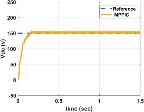
Figure 13. The Output response of the system with MPPIC plus interference (Disturbance).
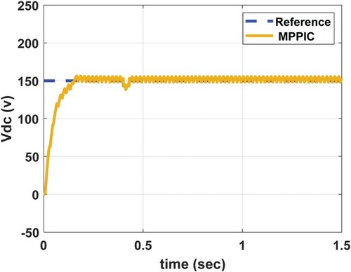
To further re-evaluate the MPPIC model’s performance, a measured disturbance of 10 V is added to the system from t=0.4 sec to 0.43 sec. The response is shown in Figure , whereas the system undershoots 1. 157%, which is greater than EMPSMC.
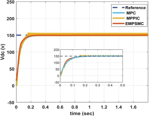
Figure shows the step response performance of the EMPSMC, MPPIC, and MPC. MPPIC responds to the reference slowly. On the contrary to this, EMPSMC responds quickly and settles down in a short time. EMPSMC performance is way better than the conventional MPC and MPPIC for tracking the reference.
Figure 14. Comparison of EMPC, MPPIC, and MPC.
Conclusion
In the proposed work, a three-phase Ac/DC power converter is controlled using the EMPSMC control strategy. The proposed scheme is the improved version of an MPPIC based approach, which depends on the system model’s designed cost function. In MPPIC, the active power reference is generated using a PI controller and is applied in the control loop. In a real-world situation, quite different systems have to deal with load variations, uncertainties, and disturbances. So, the designed controller must handle these situations adaptively and responsively to smooth these systems. However, the PI controller has constant control parameters, difficult to adjust when disturbance or load varies. The proposed EMPSMC scheme takes advantage by merging two tops of the line robust and adaptive controllers, i.e. MPC and SMC.
The designed model is validated for tracking the active power reference. Moreover, a measured disturbance is added to simulate a more rigorous analysis. The results with and without disturbance are auspicious, and the reference signal was tracked accurately. In the next stage, EMPSMC is used to supply a real-time varying load demand. The tracking of the proposed scheme was adaptive, and results showed that with the variation of demand, the proposed scheme promptly responds and adjusts the output by the change in demand.
Moreover, there is no steady-state error and significantly less over/undershoots. For the proposed scheme, the grid current and active power response are also exact and fast. The simulation model is also validated for the previous MPC and MPPIC and analysed. The proposed EMPSMC only took 0.1088 sec to reach a stable level at the desired voltage, which is only half of the time taken by the traditional MPPIC method. The overshoot of EMPSMC was 0.1886%, MPPIC was 0.8776%, and the MPC was 0.6819%. The simulation results deduce that the proposed scheme is robust, efficient, and adaptive compared to the MPPIC under different operational conditions.
A comparative study considering other modern control techniques can be a future topic of study. The proposed work is based on the control of active power. However, in the future reactive power can be studied the modern design system. The dynamic performance of the proposed control strategy can be analysed for the inductive and capacitive loads.
Acknowledgements
Open Access funding provided by the Qatar National Library.
Disclosure statement
No potential conflict of interest was reported by the author(s).
References
- Antonio, G. (2014). VSC-based MVDC railway electrification system. IEEE Transactions on Power Delivery, 29(1), 422–431. https://doi.org/https://doi.org/10.1109/TPWRD.2013.2268692
- Baghaee, H. R., Mirsalim, M., Gharehpetian, G. B., & Talebi, H. A. (2018). Decentralized sliding mode control of WG/PV/FC microgrids under unbalanced and non-linear load conditions for On- and Off-grid modes. IEEE Systems Journal, 12(4), 3108–3119. https://doi.org/https://doi.org/10.1109/JSYST.2017.2761792
- Baghaee, H., Mirsalim, M., Gharehpetian, G., Talebi, H., & Niknam-Kumle, A. (2017). A hybrid ANFIS/ABC-based online selective harmonic elimination switching pattern for cascaded multi-level inverters of microgrids. IEEE Transactions on Industrial Informatics. https://doi.org/https://doi.org/10.1109/TIE.2017.2694403
- Bordons, C., & Montero, C. (2015). Basic principles of MPC for power converters: Bridging the gap between theory and practice. IEEE Industrial Electronics Magazine, 9(3), 31–43. https://doi.org/https://doi.org/10.1109/MIE.2014.2356600
- Cao, D., & Fei, J. (2016). Adaptive fractional fuzzy sliding mode control for three-phase active power filter. IEEE Access, 4, 6645–6651. https://doi.org/https://doi.org/10.1109/ACCESS.2016.2586958
- Cho, Y., & Lee, K. B. (2016). Virtual-flux-based predictive direct power control of three-phase PWM rectifiers with fast dynamic response. IEEE Transactions on Power Electronics, 31(4), 3348–3359. https://doi.org/https://doi.org/10.1109/TPEL.2015.2453129
- Dannehl, J., Wessels, C., & Fuchs, F. W. (2009). Limitations of voltage-oriented PI current control of grid-connected PWM rectifiers with LCL filters. IEEE Transactions on Industrial Electronics, 56(2), 380–388. https://doi.org/https://doi.org/10.1109/TIE.2008.2008774
- Davari, M., & Mohamed, Y. A.-R. I. (2013). Robust multi-objective control of VSC-based dc-voltage power port in hybrid ac/dc multi-terminal microgrids. IEEE Transactions on Smart Grid, 4(3), 1597–1612. https://doi.org/https://doi.org/10.1109/TSG.2013.2249541
- He, T., Lu, D. D. C., Li, L., Zhang, J., Zheng, L., & Zhu, J. (2018). Model-predictive sliding-mode control for three-phase AC/DC converters. IEEE Transactions on Power Electronics, 33(10), 8982–8993. https://doi.org/https://doi.org/10.1109/TPEL.2017.2783859
- Kadri, R., Gaubert, J. P., & Champenois, G. (2011). An improved maximum power point tracking for photovoltaic grid-connected inverter based on voltage-oriented control. IEEE Transactions on Industrial Electronics, 58(1), 66–75. https://doi.org/https://doi.org/10.1109/TIE.2010.2044733
- Knight, J., Shirsavar, S., & Holderbaum, W. (2006). An improved reliability Cuk based solar inverter with sliding mode control. IEEE Transactions on Power Electronics, 21(4), 1107–1115. https://doi.org/https://doi.org/10.1109/TPEL.2006.876786
- Kwak, S., & Park, J.-C. (2015). Model-Predictive direct power control with vector preselection technique for highly efficient active rectifiers. IEEE Transactions on Industrial Informatics, 11(1), 44–52. https://doi.org/https://doi.org/10.1109/TII.2014.2363761
- Li, S. (2016). Design and implementation of clutch control for automotive transmissions using terminal sliding-mode control and uncertainty observer. IEEE Transactions on Vehicular Technology, 65(4), 1890–1898. https://doi.org/https://doi.org/10.1109/TVT.2015.2433178
- Liu, H., & Chen, Z. (2015). Contribution of VSC-HVDC to frequency regulation of power systems With Offshore wind generation. IEEE Transactions on Energy Conversion, 30(3), 918–926. https://doi.org/https://doi.org/10.1109/TEC.2015.2417130
- More, J. J., Puleston, P. F., Kunusch, C., & Fantova, M. A. (2015). Development and implementation of a supervisor strategy and sliding mode control setup for fuel-cell-based hybrid generation systems. IEEE Transactions on Energy Conversion, 30(1), 218–225. https://doi.org/https://doi.org/10.1109/TEC.2014.2354553
- Raeispour, M., Atrianfar, H., Baghaee, H. R., & Gharehpetian, G. B. (2020a). Robust hierarchical control of VSC-based off-grid AC microgrids to enhancing stability and FRT capability considering time-varying delays. IEEE Journal of Emerging and Selected Topics in Power Electronics. https://doi.org/https://doi.org/10.1109/JESTPE.2020.3017713
- Sebaaly, F., Vahedi, H., & Kanaan, H. Y. (2016). Sliding mode fixed frequency current controller design for grid-connected NPC inverter. IEEE Journal of Emerging and Selected Topics in Power Electronics, 4(4), 1397–1405. https://doi.org/https://doi.org/10.1109/JESTPE.2016.2586378
- Shireen, W., Kulkarni, R. A., & Arefeen, M. (2006). Analysis and minimization of input ripple current in PWM inverters for designing reliable fuel cell power systems. Journal of Power Sources, 156(2), 448–454. https://doi.org/https://doi.org/10.1016/j.jpowsour.2005.06.012
- Venkataramanan, G., & Johnson, B. K. (2003). A superconducting DC transmission system based on VSC transmission technologies. IEEE Transactions on Appiled Superconductivity, 13(2), 1922–1925. https://doi.org/https://doi.org/10.1109/TASC.2003.812947
- Zhang, X., Sun, L., & Zhao, K. (2013). Non-linear speed control for PMSM system using sliding-mode control and disturbance compensation techniques. IEEE Transactions on Power Electronics, 28(3), 1358–1365. https://doi.org/https://doi.org/10.1109/TPEL.2012.2206610