
 ?Mathematical formulae have been encoded as MathML and are displayed in this HTML version using MathJax in order to improve their display. Uncheck the box to turn MathJax off. This feature requires Javascript. Click on a formula to zoom.
ABSTRACT
Today’s world is now more interested in the robustness and automation of machines, robots, and vehicles for accurate performance in the events of external disturbances and uncertainties in the system parameters. For that purpose, a Proportional–Integral–Derivative (PID) control has found many applications in every field of industry and academics. Many methods can be used for tuning of PID, however, these methods suffer from continual variations of parameters and exterior disturbances. Therefore, a PID controller is needed that is robust to external disturbances and possess auto-tuning feature according to varying process conditions. The main motivation of this paper is to present a PID controller that is robust, continuously auto-tuned by considering uncertainties of the plant, optimize the response by minimizing the overshoot in reference tracking, and achieve stability in minimum settling time by rejecting disturbance. The earlier models can only do two tasks, tuning and optimization but this paper is proposing a contribution to such models by rejecting external disturbances and making sure the smooth running of the system. In this paper, we have done the simulation work to demonstrate the desired behaviour of the system and evaluate the effectiveness of the proposed model and a brief analysis is done by discussing the comparison between the previous work in literature and the proposed work.
1. Introduction
Feedback control is the most widely used form of the control system in the industry and robotic applications. A Proportional, Integral, and Derivative (PID) control is the most popular type of controller due to all important three elements: proportional, integral, and derivative. Proportional control improves the speed of the response, Integral control eliminates steady-state error and derivative response reduces oscillations. A Set Point (SP) is assigned to the controller and the sensor provides process variable (PV) value. The difference of SP and PV is called the error signal (e) that is fed to the controller. The controller then generates a response (u) to supply to the actuator for influencing the process variable which is then applied proportional, integral, and derivative actions.
The mathematical equation for a PID controller is given as under:
(1)
(1) where Kp, KI, and Kd denote proportional, integral, and derivative gains,
represents controller output, and
denotes the error signal which is the difference between setpoint and process variable.
The gains of the controller can be tuned by various methods such as Ziegler Nichol’s first and second methods. Softwares are also available to fine-tune the gains for desired transient and steady-state response (Dunn, Citation2005; Hughes, Citation2015).
Setpoint tracking and regulation is the primary task of the PID controller regardless of the complexity of the process. PID controller can be used for linear as well as nonlinear processes. In the non-linear processes, a limited range is usually defined in which the system can be considered as linear. For more complex processes, software-based advanced tuning of the controller will be required. One popular strategy for nonlinear processes could be using intelligent control such as fuzzy logic, Artificial Neural Networks (ANN) and Genetic Algorithms (GA) as described in the literature (Essalmi et al., Citation2014; Fan et al., Citation2015; Hernández-Alvarado et al., Citation2016).
A fuzzy controller was used for speed regulation of an ANN-based PID controller for a permanent magnet synchronous motor. The purpose of the control is direct torque control with speed regulation (Essalmi et al., Citation2014). NN based PID controller for medical applications was reported in Fan et al. (Citation2015). Alvarado et.al. presented a Neural Network (NN) based tunning method for the PID controller for underwater vehicles (Hernández-Alvarado et al., Citation2016). The controller was reported to possess the ability to tune the gains of the PID controller with the help of NNs in varying operating conditions and the system stability was proved in all varying conditions in a real environment. In Malekabadi et al. (Citation2018), the ANN and GA based tuning method of PID controller was reported that was proved to be highly robust and adaptable to varying conditions with uncertainties. The PID controller was implemented on a 9 axis quadcopter in Yoon et al., (Citation2016) with inertial measurement unit and the gains were tunned by ANN mechanism in realtime. The quadcopter was proved to be stable with smooth hovering capability.
In Zhang et al. (Citation2012), a cascade type control system has been proposed with the neuro-PID controller to regulate the superheated steam temperature with an entropy minimization algorithm instead of a squared error minimization algorithm. Feedback and feedforward types are combined in the neuro controller design and the controller can produce fewer fluctuations in temperature. In Li et al. (Citation2016), an internal model control based PID controller has been proposed for temperature control of superheated steam with the design in the frequency domain. Transfer functions are obtained in both magnitude and phase angle form and the controller gives better performance rejecting disturbances. A single neuron based adaptive PID controller has been reported in Yu et al. (Citation2017) for temperature control of superheated steam.
Disturbances are essential unwanted inputs in the practical processes that need to be controlled properly to minimize their effects on the performance and stability of the closed-loop. Various old and new methods have been presented in the survey paper ranging from numerical methods to computer simulations and various types of state observers in feedback closed-loop form (Feng & Guo, Citation2017). Various methods in literature with mathematical analysis for active disturbance rejection have been presented in the survey paper (Huang et al., Citation2010). The total disturbance modelling has been described and its effects are shown to be mitigated. The active disturbance rejection control (ADRC) has been reported in Zhao and Guo (Citation2016) for systems of type lower triangular having uncertainty terms to demonstrate robustness. An extended state observer (ESO) has been utilized for the estimation of uncertainty and asymptotic stability has been proved.
In Guo and Wu (Citation2017), constant high gain ESO has been reported with an effective response for stable performance in the presence of uncertainties in the system. A robust control insensitive to parameter variations based on ADRC was proposed in Qing et al. (Citation2009) for Micro-Electro-Mechanical Systems (MEMS) gyroscope. Simulation and experimental verifications in the field-programmable-gate-array-based controller were carried out to demonstrate the superior performance of the controller. An ADRCS for ALSTOM gasifier was proposed in Huang et al. (Citation2013) with simulation results proving its superior performance in rejecting disturbances over the PI controller. In Guo and Zhao (Citation2013), ADRC was proposed for a class of multi-input multi-output nonlinear systems with comparison to the internal model principle-based control system. Numerical analysis and simulations prove the superior performance of the proposed ADRC in terms of disturbance rejection and fast response.
The major challenges faced in the design of controllers in the event of uncertainties and disturbances are found as under: The computational complexity of the systems in the advanced nonlinear process becomes very large especially in NN based control requiring costly controllers. It is very difficult to obtain a correct plant model for controller design in the events of uncertainties that affect mathematical modelling due to unmodelled dynamics effects. All the above-mentioned works deal with the optimization, rejection of disturbances, tuning of gains, achieving a steady-state in less settling time, and less overshoot separately or by considering the combination of two features. In this paper, we have considered the maximum factors to stabilize the system using an existing older version of the model (“PID Tuning with Reference Tracking and Plant Uncertainty – MATLAB & Simulink – MathWorks India”, Citation2019). The design optimization has been done by tracking of a reference signal and optimizing the response with uncertainties in the plant model.
In this paper, our contribution is achieving the stability of the system in minimum settling time even in the presence of disturbances. The main motivation of this paper is to present a PID controller that is robust, continuously auto-tuned by considering uncertainties of plant, optimize the response by minimizing the overshoot in reference tracking, and achieve stability in minimum settling time by rejecting disturbance. The earlier models can only do two tasks, tuning and optimization but this paper is proposing a contribution to such models by rejecting external disturbances and making sure the smooth running of the system. In this paper, we have done the simulation work to demonstrate the desired behaviour of the system and evaluate the effectiveness of the proposed model and a brief analysis is done by discussing the comparison between the previous work in literature and the proposed work.
Further contents of the paper are organized as follows: methodology has been explained in Section 2, simulation, and results are presented in Section 3. Finally, the conclusion is mentioned in the last section.
2. Methodology
We have designed a PID based robust control system for dealing with uncertainties and external disturbances. The PID parameters () have been continuously tuned as per process dynamics to make the system robust. The system is ensured to remain stable i.e. bounded input will give bounded output.
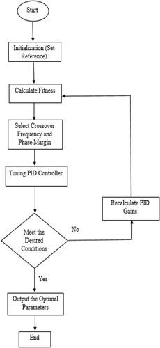
The proposed algorithm tunes the PID gains to achieve a balance between robustness and performance, and then optimize the response. The algorithm selects a crossover frequency, set a target phase margin, and then design for these parameters. If bandwidth, phase margin, or transient response vary then it will again calculate the gains for those values.
The flowchart of the proposed algorithm is given in Figure .
Figure 1. Flowchart of PID tuning.
2.1. Formulation of Minimization Problem
The minimization problem is performed in three steps:
(1). Formulation of constraints
(2). Tracking
(3). Optimization of parameters
2.1.1. Formulation of constraints
In this step, those values of parameters are determined by the algorithm that lie under the constraints upto
but the minimization of any objective function is not done at this level. And the constraints are linearly bounded
that are given below:
(2)
(2)
Then, the difference of outputs will be calculated in the following way for lower bound:
(3)
(3)
Similarly, for upper bound it will be:
(4)
(4)
If then this solution is feasible.
2.1.2. Tracking
In tracking problem, a reference signal is specified as amplitudes of time:
(5)
(5)
Then, a calculation is done for the response of simulation as following:
(6)
(6)
Here, simulation time can reach the value of
(Yu et al., Citation2017; Huang et al., Citation2010; Zhao and Guo, Citation2016).
After that the values are taken by doing union of both times and a new value is set called , while all other values that are out of this bound will be diminished.
In the next step for ,
and
will be calculated
(7)
(7)
In the final stage, the weighted integral error will be calculated by using:
(8)
(8)
2.1.3. Optimization of parameters
Finally, the minimization is done in the following way:
(9)
(9)
(10)
(10)
(11)
(11) where
is the objective function.
is contraint function,
is lower bound, and
is upper bound.
3. Results & discussion
The motivation of the proposed work to eliminate the disturbance in short settling time and track the reference signal by optimization to get the closest results when the plant is also uncertain. The system model has been presented in Figure .
Figure 2. MATLAB model for proposed algorithm.
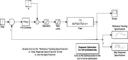
The working of the model is explained as below:
Step block is generating the input signal.
The summer block is used to subtract feedback from the step input to generate an error signal to feed to the PID block.
Disturbance block is inserted and we get the disturbance rejection from our plant for smooth running.
Saturation and Rate limits blocks are setting limits for max and min values of time and amplitude.
Plant block is shown with the uncertain transfer function in which two values in the denominator coefficients are unknown.
The scope block is giving the output signal.
The reference tracking specification block is plotting the model and giving the optimization option.
Response optimization GUI preload data is giving the design variables to compare them with the required variables.
The simulation is done by merging two models of PID tuning: one is Reference tracking and the other is disturbance rejection. We update the reference tracking model by inducing the disturbance rejection PID controller to Reference tracking and add disturbance block to it.
Figures and show the un-optimized responses by the PID controller to achieve set-point tracking and rejecting disturbances.
Figure 3. Un-optimized reference tracking specification.
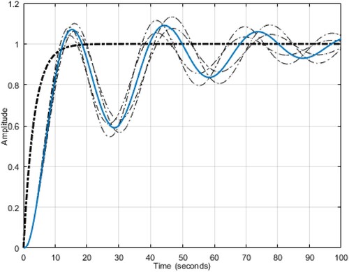
Figure 4. Un-optimized step response specification.
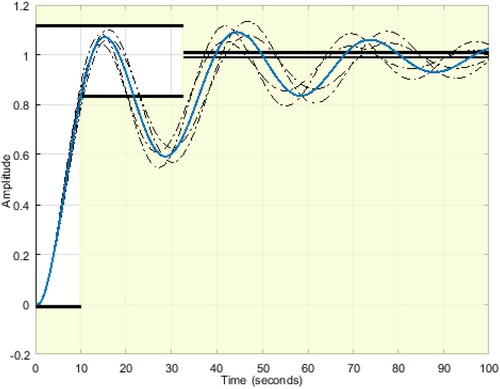
In Figures and , a predefined optimized task is launched to get the design variables to show how well the initial design specifications are satisfying the design requirements. The plant response without considering the uncertainties is indicated by the solid lines and the uncertain responses are indicated by dashed lines.
Figure 5. Optimized step response specification.
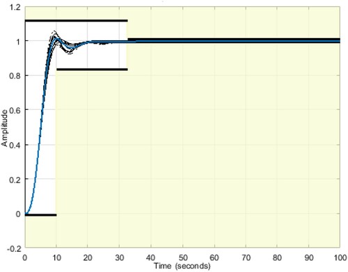
Figure 6. Optimized response of reference tracking.
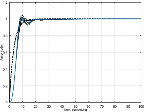
The optimization is done which lessen the difference between the response of actual and ideal model for the insignificant constraints shown with the continuous lines and the maximum/minimum measurements shown with discontinuous lines of and
. The detailed specifications are shown in Table .
Table 1. Response specifications.
Figure shows the improved disturbance rejection in less time by sliding the transient response until we get a balanced or steady response.
Figure 7. Disturbance rejection.
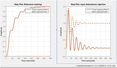
This model is an updated version of PID tuning with reference tracking and uncertain plant along with the disturbance rejection. It is now tuning the ,
,
for optimization and also rejecting the disturbance. For future work, we can add a feature of speeding up the optimization.
3.1. Comparison
In Hernández-Alvarado et al. (Citation2016), a PID is tuned on-line to control the underwater automobiles. PID gains are adjusted continuously whenever the underwater vehicle varies its parameter or has to face the currents of the ocean. In that algorithm tracking error is minimized without considering uncertainties, while by using the algorithm proposed in this paper, along-with minimization of tracking error, stability can be achieved in minimum possible time and overshoot can be made minimum. In this study, the algorithm is proposed where the disturbance rejection is also included along with the PID tuning with reference tracking in which the tracking error is minimized for optimization. It is made a two-process control not only made tracking error minimum but also decrease the settling time to achieve stability by rejecting the error in minimum possible time.
4. Conclusions
In this paper, PID controller tuning was done with a tracking reference to optimize the response and minimizing the time to get stable in the presence of uncertainty in plant and considering disturbance. In the proposed algorithm, PID gains were adjusted continuously to make the response optimized and become stable in minimum time by rejecting the disturbance. A comparison was also done with the model having only an optimization algorithm that shows that the system response of disturbance rejection after considering uncertainty has improved. This algorithm can do optimization and disturbance rejection ability to make the system stable.
In future work considerations, we are looking forward to adding some features to the model which will deal with all kind of disturbances and uncertainties by taking in to account all the necessary aspects like settling time, rise time, percentage overshoot and steady-state error at a time, to get the efficient response and we will also work on the faster response of optimization and disturbance.
Disclosure statement
No potential conflict of interest was reported by the author(s).
References
- Dunn, W. C. (2005). Process control. In Fundamentals of industrial instrumentation and process control (pp. 241–258). McGraw Hill Professional, Edition: 2.
- Essalmi, A., Mahmoudi, H., Abbou, A., Bennassar, A., & Zahraoui, Y. (2014). DTC of PMSM based on artificial neural networks with regulation speed using the fuzzy logic controller. 2014 International Renewable and Sustainable Energy Conference (IRSEC), 879–883. https://doi.org/https://doi.org/10.1109/IRSEC.2014.7059801
- Fan, J., Zhong, J., Zhao, J., & Zhu, Y. (2015). BP neural network tuned PID controller for position tracking of a pneumatic artificial muscle. Technology and Health Care, 23(s2), S231–S238. https://doi.org/https://doi.org/10.3233/THC-150958
- Feng, H., & Guo, B.-Z. (2017). Active disturbance rejection control: Old and new results. Annual Reviews in Control, 44, 238–248. https://doi.org/https://doi.org/10.1016/j.arcontrol.2017.05.003
- Guo, B.-Z., & Wu, Z.-H. (2017). Output tracking for a class of nonlinear systems with mismatched uncertainties by active disturbance rejection control. Systems & Control Letters, 100, 21–31. https://doi.org/https://doi.org/10.1016/j.sysconle.2016.12.002
- Guo, B.-Z., & Zhao, Z.-L. (2013). On convergence of the nonlinear active disturbance rejection control for MIMO systems. SIAM Journal on Control and Optimization, 51(2), 1727–1757. https://doi.org/https://doi.org/10.1137/110856824
- Hernández-Alvarado, R., García-Valdovinos, L. G., Salgado-Jiménez, T., Gómez-Espinosa, A., & Fonseca-Navarro, F. (2016). Neural network-based self-tuning PID control for underwater vehicles. Sensors, 16(9), 1429. https://doi.org/https://doi.org/10.3390/s16091429
- Huang, C.-E., Li, D., & Xue, Y. (2013). Active disturbance rejection control for the ALSTOM gasifier benchmark problem. Control Engineering Practice, 21(4), 556–564. https://doi.org/https://doi.org/10.1016/j.conengprac.2012.11.014
- Huang, Y., Xue, W., & Yang, X. (2010). Active disturbance rejection control: Methodology, theoretical analysis and applications. Proceedings of the 29th Chinese control Conference, pp. 29-31 July 2010, 6083–6090.
- Hughes, T. A. (2015). Introduction to process control. In Measurement and control basics (5th ed., pp. 1–25). International Society of Automation, Edition: 5.
- Li, X.-F., Ding, D.-J., Wang, Y.-G., & Huang, Z. (2016). Cascade IMC-PID control of superheated steam temperature based on closed-loop identification in the frequency domain. IFAC-PapersOnLine, 49(18), 91–97. https://doi.org/https://doi.org/10.1016/j.ifacol.2016.10.145
- Malekabadi, M., Haghparast, M., & Nasiri, F. (2018). Air condition’s PID controller fine-tuning using artificial neural networks and genetic algorithms. Computers, 7(2), 32. https://doi.org/https://doi.org/10.3390/computers7020032
- “PID Tuning with Reference Tracking and Plant Uncertainty – MATLAB & Simulink – MathWorks India”. (2019). Retrieved March 17, 2019, from https://in.mathworks.com/help/sldo/examples/pid-tuning-with-reference-tracking-and-plant-uncertainty.html
- Qing, Z., Lili, D., Dae, H.-L., & Zhiqiang, G. (2009). Active disturbance rejection control for MEMS Gyroscopes. IEEE Transactions on Control Systems Technology, 17(6), 1432–1438. https://doi.org/https://doi.org/10.1109/TCST.2008.2008638
- Yoon, G.-Y., Yamamoto, A., & Lim, H.-O. (2016). Mechanism and neural network based on PID control of quadcopter. 16th international conference on control, automation and systems (ICCAS), pp. 18 May 2017, 19–24. https://doi.org/https://doi.org/10.1109/ICCAS.2016.7832294.
- Yu, L., Lim, J. G., & Fei, S. (2017). An improved single neuron self-adaptive PID control scheme of superheated steam temperature control system. International Journal of System Control and Information Processing, 2(1), 1–13. https://doi.org/https://doi.org/10.1504/IJSCIP.2017.084253
- Zhang, J., Zhang, F., Ren, M., Hou, G., & Fang, F. (2012). Cascade control of superheated steam temperature with neuro-PID controller. ISA Transactions, 51(6), 778–785. https://doi.org/https://doi.org/10.1016/j.isatra.2012.06.008
- Zhao, Z.-L., & Guo, B.-Z. (2016). Active disturbance rejection control approach to stabilization of lower triangular systems with uncertainty. International Journal of Robust and Nonlinear Control, 26(11), 2314–2337. doi:https://doi.org/10.1002/rnc.3414