
 ?Mathematical formulae have been encoded as MathML and are displayed in this HTML version using MathJax in order to improve their display. Uncheck the box to turn MathJax off. This feature requires Javascript. Click on a formula to zoom.
Abstract
To make full use of the power of the microgrid and improve the reliability of the power supply system, a flexible interconnection control strategy for the DC microgrid cluster based on isolated bidirectional DC–DC converters is proposed in this paper. First, an isolated bidirectional DC–DC converter is used to flexibly interconnect the two DC microgrids based on electrical isolation to ensure that both DC microgrids can operate independently, and then the extended phase shift control is adopted for the isolated bidirectional DC–DC converter, which increases the control dimension and controls flexibility. At the same time, the extended phase shift control circuit is improved, which solves the traditional constant power transmission problem and ensures the real-time bidirectional transfer of energy between microgrids. The microgrid cluster simulation platform is built in MATLAB/Simulink, and the electrical isolation effect of the isolated bidirectional DC–DC converter is verified through simulation. At the same time, it is verified that the shift ratio of the regulating converter can realize the energy between the microgrids in the microgrid cluster, which improves the stability of the system.
1. Introduction
The microgrid is mainly composed of distributed power sources (Distributed Generator, DG), load units and energy conversion devices. It can run in two different working modes, including grid-connected and off-grid, which is currently one of the main ways to utilize renewable energy (Che et al., Citation2015; Neto et al., Citation2020; Nisar & Thomas, Citation2017). In the future, DC microgrids can provide a stable and high-quality power supply in people’s work and daily life. However, affected by the randomness and volatility of distributed power, dynamic changes in load, and the gradual increase in microgrid penetration, a single microgrid has certain limitations in maintaining the stability of the system bus voltage and power balance. In order to improve the energy utilization rate of the microgrid, it is an inevitable trend in the development of distributed energy supply systems to realize the flexible interconnection and high-efficiency applications between DC microgrids (Li et al., Citation2019; Zandi et al., Citation2018).
In response to the above problems, some scholars have put forward the concept of microgrid cluster, which is an extension of single microgrid structure and function expansion, and the interconnection of multiple single microgrids is used to enhance the reliability of the power supply of the system (Guo et al., Citation2019; He & Giesselmann, Citation2015; Li et al., Citation2018; Yu et al., Citation2017). In a microgrid cluster, flexible interconnection is the guarantee for stable operation between microgrids. At present, isolated bidirectional DC–DC converters are usually used to achieve flexible interconnection between microgrids. It has the function of electrical isolation and two-way control of energy transfer (Gorji et al., Citation2019; He & Khaligh, Citation2017; Wu et al., Citation2018). Isolated bidirectional DC–DC converters mainly use phase-shift control to control the bidirectional flow of energy between interconnected microgrids. In Gu et al. (Citation2020), single-phase-shift control is introduced when the primary, secondary bridge of the isolated bidirectional DC–DC converter is triggered and turned on. There is a phase-shift angle, and this phase shift angle is defined as the external phase shift angle. The magnitude and direction of energy transfer are controlled by adjusting the magnitude of the external phase-shift angle. The single-phase shift control principle is simple, and the system responds quickly under control. But the control dimension is low, and its flexibility is poor. In order to improve the flexibility of converter control, a double-phase shift control is introduced (Haneda & Akagi, Citation2020; Li & Shi, Citation2019), which is different from single-phase shift control in that there is an external phase shift when the original secondary bridge is triggered and turned on. In addition to the angle, when the diagonal arm of the primary side and the secondary side bridge is triggered to conduct, there is a phase shift angle of the same angle at the same time. This phase shift angle is defined as the internal phase shift angle, which not only increased the dimension and flexibility of control compared with the single-phase shift control but also increased the complexity of control. Triple-phase shift control is proposed in Luo and Wu (Citation2018). The difference between it and double-phase shift control is that there is a different angle of shift between the primary and secondary bridges. There is a different phase shift angle at the same time when the conduction is triggered. It increases the dimension of control based on double-phase shift control, which makes the control more flexible, but also increases the complexity of the control. In order to improve the overall performance of the converter control, an extended phase shift control is proposed in Xu et al. (Citation2018). In addition to the fact that there is an external phase shift angle when the primary and secondary bridges of the converter are triggered to conduct, at the same time, the internal diagonal bridge arms of the primary bridge are triggered to conduct conduction. When it is connected, there is a phase shift angle, which is defined as the internal shift phase angle. The extended phase shift control combines the advantages of single-phase shift control, double-phase shift control and triple-phase shift control. It is relatively single shift Phase control that increases the flexibility of control and reduces the complexity of control for double-phase shift control and triple-phase shift control.
In this paper, the microgrid in the microgrid cluster can effectively isolate local electrical faults directly through the flexible interconnection of isolated bidirectional DC–DC converters and improve the power supply reliability of the system; the extended phase shift control is adopted for the isolated bidirectional DC–DC converter, which increases the dimension of control. The control becomes more flexible, and the traditional extended phase shift control circuit is improved. By adjusting the shift phase of the converter, the real-time bidirectional transfer of energy between the microgrids in the microgrid cluster can be realized, which improves the stability of the system.
2. Topological structure and circuit diagram
2.1. Topological structure diagram
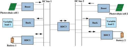
The microgrid cluster is composed of two microgrids in this paper. The topology is shown in Figure . The two DC microgrids are connected by isolated bidirectional DC–DC converters. Each microgrid is mainly composed of photovoltaic cells, batteries and loads. Among them, the photovoltaic cells, and the batteries are connected to the bus through the Boost converter and the bidirectional DC–DC converter (BDC), and the load is connected to the bus through the Buck converter. This paper mainly studies the control strategy of isolated bidirectional DC–DC converters, when power imbalance occurs in the microgrid, the bidirectional energy transfer between the microgrids can be realized while ensuring the electrical isolation of the microgrids.
Figure 1. Topological structure diagram of DC microgrid cluster.
2.2. Circuit structure diagram
The circuit structure of the DC microgrid cluster studied in this paper is shown in Figure . The flexible interconnection between the microgrids is realized through the control of the isolated bidirectional DC–DC converter. According to this method, it can be expanded into a microgrid cluster with flexible interconnection between multiple DC microgrids.
Figure 2. DC microgrid cluster structure diagram.
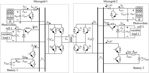
In Figure , ,
,
and
are respectively the output current of the photovoltaic cells of the microgrid 1 in the microgrid cluster through the Boost converter, the input current of the Buck converter, the output current of the battery through BDC and the input current of the isolation BDC.
,
,
and
are respectively, the energy storage inductances of the Boost converter, Buck converter, BDC and isolated BDC of microgrid 1.
and
are the bus voltage and filter capacitor of microgrid 1, respectively.
,
,
and
are respectively the output current of the photovoltaic cells of the microgrid 2 in the microgrid group through the Boost converter, the input current of the Buck converter, the output current of the battery through the BDC and the isolated BDC input current.
,
and
are respectively, the Boost converters of the microgrid 2, The energy storage inductance of Buck converter and BDC.
and
are respectively, the bus voltage and filter capacitance of microgrid 2. The current relations of microgrid 1 and microgrid 2 are obtained from Kirchhoff’s current law as follows Equations (1) and (2):
(1)
(1)
(2)
(2)
The positive and negative of and
in the above Equations (1) and (2) are related to the operating status of microgrid 1 and microgrid 2. When the photovoltaic output power in microgrid 1 is less than the load consumption and the battery cannot support the power shortage,
in formula (1) is a negative value, and
in formula (2) is a positive value. Energy is transferred from microgrid 2 to microgrid 1, to provide energy replenishment for the microgrid and maintain the stability of its bus voltage. The same applies to microgrid 2 when the photovoltaic output power in the power grid is less than the load consumption, and the battery cannot support the power shortage,
in formula (1) is a positive value and
in formula (2) is a negative value. The energy is transferred from microgrid 1 to microgrid 2, which provides Grid 2 with energy replenishment to maintain the stability of bus voltage. When both microgrid 1 and microgrid 2 have power shortages, it is necessary to purchase energy from the large grid. In this case, both
and
in Equations (1) and (2) are negative. When microgrid 1 and microgrid 2 have a power surplus, and the energy storage reaches the upper limit, the excess power will be transmitted to the large grid. At this time,
and
in Equations (1) and (2) are both positive. This article only considers the situation when a single microgrid in a microgrid cluster has a power shortage.
3. Isolated bidirectional DC–DC converter
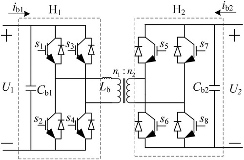
The structure of the isolated bidirectional DC–DC converter is shown in Figure . It is mainly composed of two full-bridge converters and
, two stabilizing capacitors
and
, an energy storage inductor
and an isolation transformer.
and
are respectively, the number of turns of the transformer on the primary side and the secondary side, defining
;
is the switching
frequency.
Figure 3. Diagram of isolated bidirectional DC–DC converter.
3.1. Single-phase shift control
Traditional isolated bidirectional DC–DC converters generally use single-phase shift control (Single-Phase Shift SPS). In single-phase shift control, the trigger signals of bridges and
have a certain phase shift angle
, which defines the half cycle of ratio
and
switch as the shift ratio d, and the direction and size of the power transmission are controlled by adjusting d. The expression of the transmission power P is as follows (3):
(3)
(3) In the above formula (3), the value range of d is
. When
, energy flows from microgrid 1 to microgrid 2. When
, energy flows from microgrid 2 to microgrid 1. The control structure is shown in Figure .
Figure 4. Single-phase shift isolated bidirectional DC–DC converter control structure diagram.
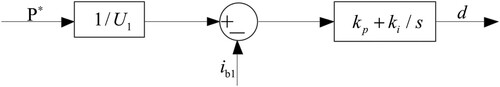
The traditional single-phase shift control gives the transmission power , and adjusts the shift phase
through PI control to reach the designated transmission power. However, the single-phase shift control has a low dimension, poor control flexibility and cannot self-adjust power transmission in real-time.
3.2. Extended phase shift control
Aiming at the limitation of single-phase shift control, this paper adopts EPS (Extended Phase Shift, EPS) to increase the dimension of control. In the extended phase shift control, there is a phase shift angle for the drive signal between the two diagonal switch tubes in the
bridge. At the same time, the driving signals of the primary side
and the secondary side
have a certain phase shift angle
, the ratio of
and the half time period of
switch is defined as the internal shift ratio
, and the ratio of
and the half time period of
switch is defined as the outer shift ratio
, by adjusting the shift ratio
and
, the size and direction of the converter power transmission can be controlled, and the transmission power P expression is shown in the following Equation (4) (Xu et al., Citation2018):
(4)
(4)
It can be seen from (Xu et al., Citation2018) that the outward shift ratio in formula (4) is usually determined by analysis, and its value range is
to achieve energy by controlling the constant power transmission of the dual active ends of the isolated bidirectional DC/DC converter. The structure diagram of the extended phase shift control is shown in Figure below.
Figure 5. Control structure diagram of extended-phase shift isolation bidirectional DC/DC converter.
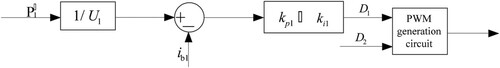
In the above Figure , the control process is as follows: firstly, set the transmission power, and after determining the outer shift ratio, PI control is used to adjust the shift ratio to reach the specified transmission power. Although the dimension of control is increased, the situation of constant power transmission is still not changed and the application of non-linear time-varying systems is unsuitable.
To solve the deficiencies of the extended phase shift control and meet the non-linear time-varying microgrid control system, this paper improves the control structure of the isolated bidirectional DC/DC converter, as shown in Figure . The energy transfer direction is controlled according to the deviation between the given voltage value and the actual value. When the actual voltage value is lower than the reference value, the microgrid system is in a power shortage state. Energy needs to be absorbed at this time. When the actual voltage value is higher than the reference value, the microgrid system is in a power surplus state, and energy needs to be output at this time. When there is energy transfer between interconnected microgrids, selector 1 connected to the bus voltage deviation will output a larger value of the bus voltage deviation, and this deviation value will be output through the selector 2 connected to the PI control. When there is no energy transfer between the microgrids, the output value of the selector 2 connected to the PI control is 0 at this time.
Figure 6. Control structure diagram of extended-phase shift isolation bidirectional DC/DC converter.
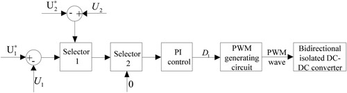
The process of converter control energy transfer in Figure above is: after determining the value of , the value output by the selector is adjusted by PI control to adjust the phase shift angle
, thereby, changing the size of the internal shift compared to
, and then passing through the PWM generating circuit Generate the corresponding PWM wave to control the converter. Here the energy transfer direction has been controlled by the bus voltage deviation value, so we only need to consider the value range of
to adjust the energy transfer size, take its value range as
, and transform the value of
through multiple simulations to obtain the reliability of the system at
, it is found that the reliability of the system is better. So this article uses
.
4. Simulation verification and analysis
According to the DC microgrid cluster shown in Figure , a simulation model is built in MATLAB/Simulink, and the system simulation parameters are shown in Tables .
Table 1. Simulation parameters of DC microgrid 1 system.
Table 2. Simulation parameters of DC microgrid 2 system.
Table 3. Simulation parameters of isolated bidirectional DC–DC converter.
In order to verify the electrical isolation effect of the isolated bidirectional DC–DC converter and the real-time bidirectional transfer of energy between the microgrids under the flexible interconnection control strategy of the converter, the following simulations are carried out:
Working condition 1: The simulated fault of DC microgrid 2 is disconnected at 2 s, and the bus voltage simulation of each microgrid is shown in Figure .
Figure 7. DC bus voltage diagram.
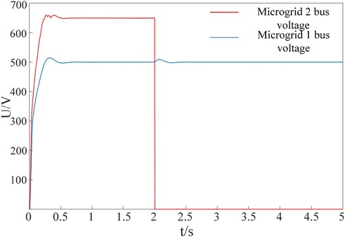
In Figure above, the bus voltages of microgrid 1 and microgrid 2 stabilize at a given voltage value of 500V and 650 V around 0.5 s, respectively.
When the simulation runs for 2 s, the simulated fault of microgrid 2 is disconnected, and its bus voltage is directly reduced from 650 V to 0 V. The extended phase shift control circuit detects that the fluctuation of the bus voltage exceeds the adjustment range, and isolates the two-way DC/DC converter directly. Due to the bidirectional transfer of energy in the isolated bidirectional DC/DC converter, the bus voltage of microgrid 1 will fluctuate due to the failure of microgrid 2, but the bus voltage of microgrid 1 fluctuates slightly and then returns to 500 V, which proves isolate the electrical isolation effect of the bidirectional DC/DC converter.
Working condition 2: Microgrid 1 in the microgrid cluster is connected to the resistance of 3 at 1.5 s, and a simulation diagram of the two microgrid systems in the microgrid cluster is given. The obtained waveforms are shown in Figures . The simulation results verify that the isolated bidirectional DC/DC converter controls the real-time transfer of energy in the microgrid cluster to maintain the stable operation of each microgrid system in the microgrid cluster and the power conservation of the microgrid cluster system.
Figure 8. The bus voltage diagram of microgrid 1 with sudden load.
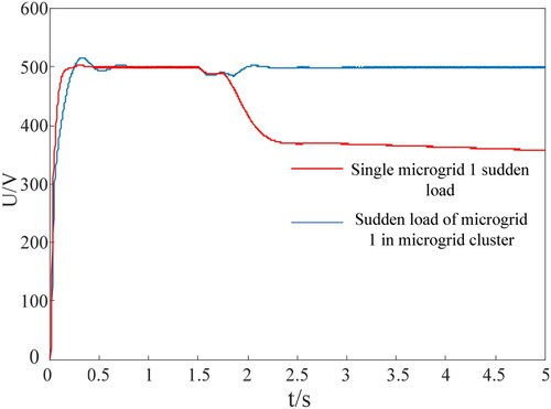
Figure 9. Power diagram of DC microgrid 1.
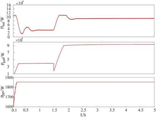
Figure 10. Power diagram of DC microgrid 2.
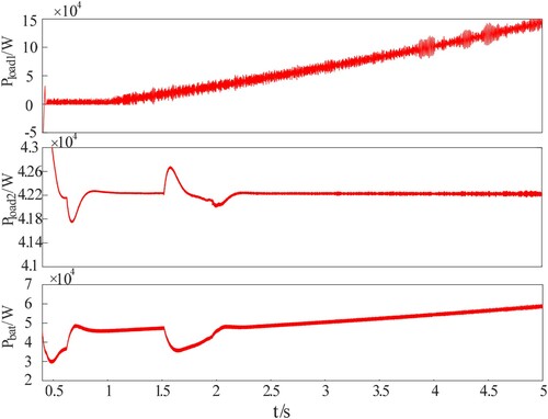
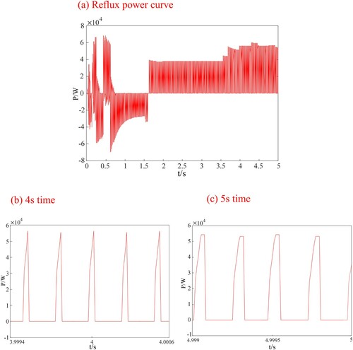
Figure 11. Reflux power 1 diagram (a) Reflux power curve, (b) 4 s time, (c) 5 s time.
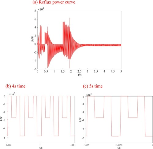
It can be seen from Figure that after the 3-resistor is connected, the stability of the microgrid is affected, but the microgrid in the microgrid cluster can quickly restore stability. Figure shows the power curves of the microgrid 1 energy storage battery, resistive load and photovoltaic cell. Figure shows the power curves of the microgrid 2 motor load, resistive load and energy storage battery. The starting time is 0.4 s. The photovoltaic cell power curve is not shown in the figure, but the curve is the same as that of microgrid 1. Figure shows the return power curve of the microgrid cluster.
Taking time points 1 as 4 s, the power of resistive load, photovoltaic cell and energy storage battery in Figure are about 93,285, 1850 and 92400 W, respectively. At this time, the return power loss is about 4,735W, so the microgrid 1 side is short of −3,770 W. The power of motor load, resistance load and energy storage battery in Figure is about 10,000, 42,200 and 54,150 W, respectively, so the output power of microgrid 2 is about 3800 W. Taking time points 2 as 5 s, the resistance load and energy storage battery power in Figure above are about 93,333 and 92,636 W, respectively. At this time, the return power loss is about 4735 W, so the microgrid 1 side is short of −3582 W. In Figure , the motor load, the power of resistive load and energy storage battery is about 14,300, 42,250 and 58,300 W, so the output power of microgrid 2 is about 3600 W. Counting the charge and discharge of the inductive load in the line and the loss of impedance and return power, the energy of the microgrid cluster system is conserved, which verifies the real-time transfer of energy from the bridge to the bridge under the flexible interconnection of the microgrid cluster.
Working condition 3: Microgrid 2 in the microgrid cluster is connected to the resistance of 8 at 1.5 s, and a simulation diagram of the two microgrid systems in the microgrid cluster is given. The obtained waveforms are shown in Figures . The simulation results verify that the isolated bidirectional DC/DC converter controls the real-time transfer of energy in the microgrid cluster to maintain the stable operation of each microgrid system in the microgrid group and the power conservation of the microgrid cluster system.
Figure 12. Voltage diagram of microgrid 2 sudden load bus.
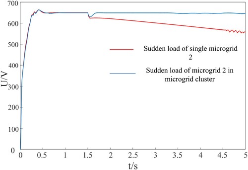
Figure 13. Power diagram of DC microgrid 1.
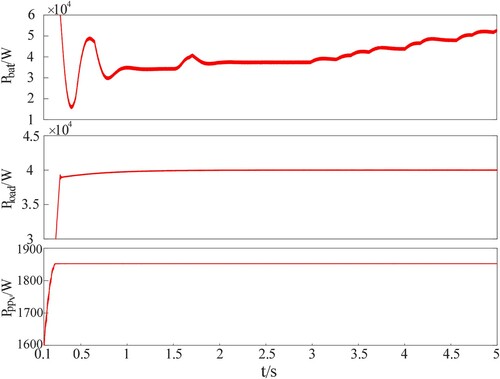
Figure 14. Power diagram of DC microgrid 2.
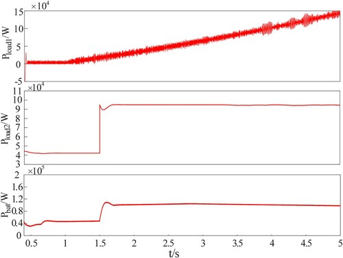
Figure 15. Reflux power 2 diagram (a) Reflux power curve, (b) 4 s time, (c) 5 s time.
It can be seen from Figure that after the 8-resistor is connected, the stability of the microgrid is also affected, but the microgrid in the microgrid cluster can quickly restore stability. Figure shows the power curves of microgrid 1 energy storage battery, resistive load and a photovoltaic cell. Figure shows the power curves of microgrid 2 motor load, resistive load and energy storage battery. The starting time is also 0.4 s; the photovoltaic cell power curve is not shown in the figure, but its curve is the same as that of microgrid 1. Figure shows the return power curve of the microgrid cluster.
Similarly, take time point 3 as 4 s. In Figure , the power of resistive load, photovoltaic cell and energy storage battery are about 40,000, 1850 and 44,255 W, respectively. At this time, the return power loss is about 3781 W, and the output power of microgrid 1 is about 2324 W. The power of the motor, resistor and energy storage battery in Figure is about 10,580, 94,333 and 100,760 W, respectively, so the output power of the microgrid 2 is about −2303 W. Taking time points 4 as 5 s, the power of resistive load, photovoltaic cell and energy storage battery in Figure is about 40,000, 1850 and 50,000 W, respectively. At this time, the return power loss is about 3375 W, and the output power of microgrid 1 is about 8475 W. The power of the motor, resistor and energy storage battery in Figure is about 14,500, 93,950, and 98,150 W, respectively, so the output power of microgrid 2 is about −8450 W. Counting the charge and discharge of the inductive load in the line and the loss of impedance and return power, the energy of the microgrid cluster system is conserved, which verifies the real-time transmission of energy from the bridge to the bridge under the flexible interconnection of the microgrid cluster.
5. Conclusion
Aiming at the problem of electrical fault isolation and real-time bidirectional transfer of energy between the microgrids in the off-grid DC microgrid cluster, this paper uses isolated bidirectional DC–DC converters for flexible interconnection between the microgrids. When the microgrid cluster operates stably, one of the microgrids simulates a failure and analyses the influence of the faulted microgrid on the stability of the interconnected microgrid. At the same time, the principle of converter control energy transfer is studied, and the extended phase shift control is adopted for the converter to observe the energy flow between the microgrids when there is a power shortage. According to the simulation analysis, the following conclusions are drawn:
The isolated bidirectional DC–DC converter realizes electrical isolation between interconnected microgrids and can effectively isolate faulty microgrids. It meets the plug and play of a single microgrid and increases the flexibility of microgrid cluster control.
The isolated bidirectional DC/DC converter adopts extended phase shift control. Compared with the constant power transmission of single-phase shift control, the extended phase shift control increases the dimension of control and makes the control more flexible.
The control circuit of the improved and extended phase-shifting control in this article can adjust the real-time bidirectional transfer of energy between the microgrids by real-time detecting the size of the busbar voltage in the microgrid cluster, maintaining the voltage stability and power balance of the microgrid cluster, and changing the traditional limitations of constant power transmission.
The improved extended phase shift circuit is more suitable for non-linear time-varying microgrid systems, but it will also produce certain errors and lead to power transmission losses.
Disclosure statement
No potential conflict of interest was reported by the author(s).
Additional information
Funding
References
- Che, L., Shahidehpour, M., Alabdulwahab, A., & Al-Turki, Y. (2015). Hierarchical coordination of a community microgrid with AC and DC microgrids. IEEE Transactions on Smart Grid, 6(6), 3042–3051. https://doi.org/https://doi.org/10.1109/TSG.2015.2398853
- Gorji, S. A., Sahebi, H. G., Ektesabi, M., & Rad, A. B. (2019). Topologies and control schemes of bidirectional DC–DC power converters: An overview. IEEE Access, 7, 117997–118019. https://doi.org/https://doi.org/10.1109/ACCESS.2019.2937239
- Gu, H., Li, X., Guo, L., & Li, P. (2020). Flexible interconnection and control of multiple DC microgrid groups. Proceedings of the CSU-EPSA, 32(4), 1–8. https://doi.org/https://doi.org/10.19635/j.cnki.csu-epsa.000286
- Guo, L., Li, P., Li, X., Huang, D., & Zhu, J. (2019). Flexible control of DC interlinked multiple MGs cluster. Transmission & Distribution, 13(11), 2088–2101. https://doi.org/https://doi.org/10.1049/iet-gtd.2018.5376
- Haneda, R., & Akagi, H. (2020). Design and performance of the 850-V 100-kW 16-kHz bidirectional isolated DC–DC converter using SiC-MOSFET/SBD H-bridge modules. IEEE Transactions on Power Electronics, 35(10), 10013–10025. https://doi.org/https://doi.org/10.1109/TPEL.2020.2975256
- He, M., & Giesselmann, M. (2015). Reliability-constrained self-organization and energy management towards a resilient microgrid cluster. In: IEEE Power & Energy Society Innovative Smart Grid Technologies Conference (ISGT), Washington, DC (pp. 1–5).
- He, P., & Khaligh, A. (2017). Comprehensive analyses and comparison of 1 kW isolated DC–DC converters for bidirectional EV charging systems. IEEE Transactions on Transportation Electrification, 3(1), 147–156. https://doi.org/https://doi.org/10.1109/TTE.2016.2630927
- Li, R., & Shi, F. (2019). Control and optimization of residential photovoltaic power generation system with high efficiency isolated bidirectional DC–DC converter. IEEE Access, 7, 116107–116122. https://doi.org/https://doi.org/10.1109/ACCESS.2019.2935344
- Li, X., Guo, L., Li, Y., Hong, C., Zhang, Y., Guo, Z., Huang, D., & Wang, C (2018). Flexible interlinking and coordinated power control of multiple DC microgrids clusters. IEEE Transactions on Sustainable Energy, 9(2), 904–915. https://doi.org/https://doi.org/10.1109/TSTE.2017.2765681
- Li, X., Li, Z., Guo, L., Huang, D., Li, P., Zhu, J., & Wang, C. (2019). Flexible control and stability analysis of AC–DC microgrid cluster. Proceedings of the CSEE, 39(20), 5948–5961. https://doi.org/https://doi.org/10.13334/j.0258-8013.pcsee.181950
- Luo, S., & Wu, F. (2018). Hybrid modulation strategy for IGBT-based isolated dual-active-bridge DC–DC converter. IEEE Journal of Emerging and Selected Topics in Power Electronics, 6(3), 1336–1344. https://doi.org/https://doi.org/10.1109/JESTPE.2018.2843356
- Neto, P. J. d. S., Barros, T. A. d. S., Silveira, J. P. C., Filho, E. R., Vasquez, J. C., & Guerrero, J. M. (2020). Power management strategy based on virtual inertia for DC microgrids. IEEE Transactions on Power Electronics, 35(11), 12472–12485. https://doi.org/https://doi.org/10.1109/TPEL.2020.2986283
- Nisar, A., & Thomas, M. S. (2017). Comprehensive control for microgrid autonomous operation with demand response. IEEE Transactions on Smart Grid, 8(5), 2081–2089. https://doi.org/https://doi.org/10.1109/TSG.2016.2514483
- Wu, M., Hou, N., Song, W., & Jiang, W. (2018). Independent input parallel output full-bridge isolated DC–DC converter direct power balance control. Proceedings of the CSEE, 38(5), 1329–1337. https://doi.org/https://doi.org/10.13334/j.0258-8013.pcsee.171291
- Xu, H., Zeng, Z., Ran, L., Liu, Q., & Song, C. (2018). Return power optimization of bidirectional active bridge converter based on extended phase shift control. Proceedings of the CSEE, 38(23), 7004–7014. https://doi.org/https://doi.org/10.13334/j.0258-8013.pcsee.171521
- Yu, J., Ni, M., Jiao, Y., & Wang, X. (2017). Plug-in and plug-out dispatch optimization in microgrid clusters based on flexible communication. Journal of Modern Power Systems and Clean Energy, 5(4), 663–670. https://doi.org/https://doi.org/10.1007/s40565-016-0235-2
- Zandi, F., Fani, B., Sadeghkhani, I., & Orakzadeh, A. (2018). Adaptive complex virtual impedance control scheme for accurate reactive power sharing of inverter interfaced autonomous microgrids. IET Generation, Transmission & Distribution, 12(22), 6021–6032. https://doi.org/https://doi.org/10.1049/iet-gtd.2018.5123