
 ?Mathematical formulae have been encoded as MathML and are displayed in this HTML version using MathJax in order to improve their display. Uncheck the box to turn MathJax off. This feature requires Javascript. Click on a formula to zoom.
Abstract
This paper presents novel maximum torque per ampere (MTPA) and maximum power per ampere (MPPA) sliding mode control (SMC) approaches for interior permanent-magnet synchronous motors (IPMs). We first derive the first-order SMC methods to improve the field-oriented control's resiliency against the external perturbations, extraneous noise and modelling uncertainties. After that, we propose the higher-order SMC to significantly reduce the chattering phenomenon, which is inherent in the first-order sliding mode method. Based on the comparison studies, the conventional proportional-integral-derivative based field oriented control shows sluggish response and is more sensitive to parameter perturbations and external torque disturbances. By introducing the novel SMC methods, both the speed and torque regulation performance of interior permanent magnet synchronous motor can be greatly improved. Computer simulation studies have demonstrated the superior performance of the first-order and higher-order sliding mode controllers for interior permanent magnet synchronous motor speed and torque regulation applications.
1. Introduction
Permanent magnet synchronous motors (PMs) have been widely used for industrial applications due to their large torque to inertia ratio, high power density, high power factor, extended bearing and efficient insulation life time, superior energy efficiency and great dependability.
In field-oriented control method, is set to zero to avoid demagnetization effect. With the introduction of permanent magnets of high coercive forces, there is no need to bound to this method. The competence of IPM motor along with demanded inverter capacity depends on the current phase control methods, i.e. controlling the phase angle β of armature current. The current phase control methods are
control method,
control method and constant flux linkage control method. The
method is used for surface-mounted motor as torque is linear to armature current, high torque performance is obtained and no demagnetization effect is seen. In
control method, torque per armature current is small and torque is nonlinear in nature, hence its best suitable for constant speed drive applications. Constant flux linkage method gives torque characteristics closer to linear and required inverter capacity is small, hence its best suited for interior permanent magnet synchronous motor Uddin et al.(Citation2002).
In conventional DC motors, magnetic flux can be directly reduced to increase the speed operation range. However, for permanent magnet synchronous motors, air gap flux needs to be decreased by direct-axis armature current. This method is commonly known as ‘flux-weakening’. Morimoto et al. conducted experiments in which several motor parameters were examined under wide-speed operation range and the results are summarized as follows (Morimoto et al., Citation1993; Morimoto, Sanada et al., Citation1994; Morimoto et al., Citation1990a, Citation1990b):
The operating limits can be increased by controlling the d and q axis armature currents according to rotor speed.
If the supply voltage is less than rated voltage, operating region can be large. If both are equal, ideal output characteristics can be obtained. However, if the power supply voltage is less than rated voltage, then at low speed range, the output power can be large, but wide-speed operation is not possible.
Due to the saliency, IPM motor has additional torque component called reluctance torque. Hence, the output torque can be large.
In the constant power regions, permanent magnet with high coercivity and linear demagnetization curve should be used.
The flux weakening control is used for constant power operation. Due to saliency in IPM motor, reluctance torque can be productively used by MTPA control to generate large torque. Several characteristics such as torque, power factor, efficiency, and transient response are examined and are compared with control method. By controlling d-axis, current torque per ampere is large and power factor is improved compared to
method.
Traditional Proportional-Integral (PI)-based control techniques are still the most widely utilized method due to the ease of implementation and simplicity. However, it is sensitive to uncertainties and disturbance. Therefore, nonlinear and robust control techniques were proposed and implemented to boost the permanent magnet synchronous motor control performance.
To improve the traditional PI-based field-oriented control, various advanced control approaches have been developed, including sliding mode control (SMC), model predictive control, adaptive control and robust control, intelligent control. The SMC is one of the most promising next-generation control scheme for power electronics and power systems. The philosophy behind SMC is to design a function called sliding variable which becomes zero on the sliding manifold. The systems performance depends on the proper selection of sliding variables Utkin et al. (Citation1999). SMC guides the trajectory of the system to the sliding surface and keeps the movement of trajectory along the surface with the switching control law. The advantages with sliding mode are its superior resiliency to external disturbances and perturbations, high accuracy and fast dynamic response.
SMC design is a two-step procedure: The first step is to choose a control law, which will steer the systems state to sliding surface even during troublesome environments. And the second step is to create a switching function that keeps the system trajectory on the sliding surface satisfying the design specifications. The first-order SMC is ineffective in eliminating the unwanted phenomenon chattering. This phenomenon occurs due to non-ideal switching devices and time delays in processors. The higher-order SMC for PM motors was presented in Levant and Fridman (Citation2002) and higher-order observer of PM motor was implemented in Xu and Rahman (Citation2003). The higher-order SMC has been the preferred approach, since it is more effective in eliminating chattering phenomenon and achieving superior dynamic performance (Wang et al., Citation2016, Citation2018).
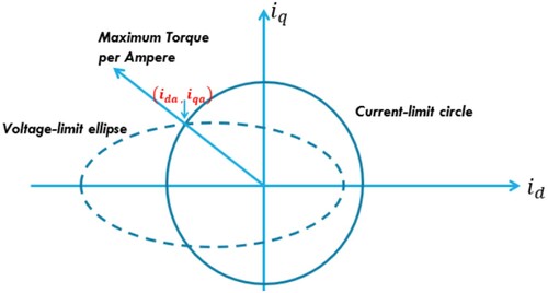
Leveraging our previous effort in Alnami et al. (Citation2021), in this paper, novel first-order and super-twisting-based second-order SMC for interior permanent magnet synchronous motor drives are derived. The interior permanent magnet synchronous motor drives, which have been widely used for modern electrified vehicles, can achieve maximum torque per ampere (MTPA) and maximum power per ampere (MPPA) performance via the proposed SMC methods, as illustrated in . The conditions for MTPA and MPPA control of IPMs are derived in this paper. In addition, both control methods are compared with the traditional PI control for the MTPA and MPPA control of IPMs. While both sliding methods show exceptional performance in transient response, guaranteed Lyapunov stability, robustness against the modelling uncertainties and extraneous disturbances, the second-order SMC is superior in eliminating the chattering phenomenon which is inherent in the first-order approach.
Figure 1. MTPA and MPPA trajectory.
This paper is organized as follows: Section 2 provides dynamical model of IPMs. Sections 3 and 4 present the direct-axis reference current 's derivations, conditions to apply MTPA and MPPA, disadvantages of PI controller, advantages of SMC. In Section 5, first-order SMC is proposed. Section 5 also presents the design of the super-twisting-based second-order SMC. Section 6 explains the computer simulation results. Section 7 concludes the paper.
2. Interior permanent magnet synchronous motor model
The direct and quadrature axis stator voltage equation in the dq coordinates frame can be described as Krause et al. (Citation2013)
(1)
(1)
Equation (Equation1
(1)
(1) ) can be expressed in current frame of reference as
(2)
(2)
(3)
(3)
where
represents the direct-axis current,
stands for the quadrature-axis current, R is the resistance of the stator, rotor mechanical speed is
,
and
denote the direct-axis and quadrature-axis inductance, respectively.
The mechanical equation can be written as
(4)
(4)
where B represents the damping coefficient, J denotes the moment of inertia,
is the mechanical torque, where the number of poles is P, and
represents the flux linkage. And
denotes the electromagnetic torque satisfies
(5)
(5)
Notice that w and
are the electrical and mechanical speed, respectively. The relation between electrical and mechanical rotor speed is
(6)
(6)
The direct
and
currents can be represented in terms of armature current and phase angle as follows:
(7)
(7)
where
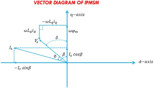
is the magnitude of armature current per phase. β is the leading angle of armature current vector from the q axis, as shown in .
Figure 2. IPM's vector diagram.
The torque can be represented as
(8)
(8)
3. Maximum torque per ampere (MTPA)
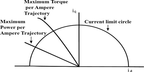
The maximum torque point can be reached at intersection point between current-limit circle and MTPA's trajectory as shown in Figure .
Figure 3. MTPA's trajectory.
Direct-axis and quadrature-axis current need to be derived by taking the derivative of developed torque with respect to β and equating it to zero.
(9)
(9)
After simplification, Equation (Equation9
(9)
(9) ) can be rewritten as
(10)
(10)
Therefore, angle β can be calculated by
(11)
(11)
The reference direct-axis current
and quadrature-axis current
can be calculated by substituting Equation (Equation11
(11)
(11) ) into Equation (Equation7
(7)
(7) ) as
(12)
(12)
After simplification,
can be written as
(13)
(13)
4. Maximum power per ampere (MPPA)
When the motor speed is greater than the rated speed, the current vector producing cannot satisfy the voltage constraint above the rated speed. The d- and q-axis armature current components are controlled in order to keep the rated voltage
equal to supply voltage in the flux-weakening constant power region. The relationship between
and
of the flux-weakening control is derived as follows:
(14)
(14)
with
(15)
(15)
Equivalently, we have
(16)
(16)
Therefore, the reference direct-axis stator current can be calculated by:
(17)
(17)
which can be further simplified as
(18)
(18)
When the motor speed is less than the rated speed, MTPA control is utilized. And when rotor speed is greater than the rated speed, MPPA control is applied. Classical PI controllers are used in the traditional field oriented control for motor speed and torque regulation. The traditional field oriented control uses space vector pulse width modulation (SVPWM) techniques to obtain the required voltage from inverter to the IPM motor. The currents from an IPM are converted from abc frame of reference to
frame using Clarke's transformation and to dq frame of reference using Park's transform. The PI controllers requires decoupling stage and back-emf compensation. By performing decoupling, the two inputs
,
serves as the input signals to SVPWM.
5. Sliding mode control
SMC is a nonlinear control method which enjoys inherent robustness, flexibility of design and the ease to be implemented with microprocessors. The complete detailed analysis of SMC can be found in Wang et al. (Citation2018).
Consider a nonlinear system
(19)
(19)
where
is state variable,
and
are vector fields in the same space and
is the discontinuous control defined as
where
is sliding variable and chosen such that state variables follow their desired trajectories.
and
are function of
. A system exhibits SMC when the reachability, existence and stability conditions are met.
The reachability conditions make the trajectories of system reach the sliding surface.
Mathematically, it can be defined as
(20)
(20)
The existence condition always direct the trajectory towards sliding surface, which can be stated as
(21)
(21)
The stability condition ensures the sliding surface directs trajectory towards stable equilibrium.
5.1. Sliding surfaces
Consider the following slide manifolds:
(22)
(22)
(23)
(23)
(24)
(24)
5.2. Parameter uncertainties
Due to unmodelled dynamics present in the mathematical model of an IPM, R is defined as , where
is nominal resistance and
is a bounded disturbance. Similarly,
,
,
,
, and
.
5.3. First-Order sliding mode control design
5.3.1. First-order flux sliding mode control
The direct-axis flux control is given as
(25)
(25)
where
is the equivalent control and
is the switching control. The equivalent control can be solved by taking derivative of
.
(26)
(26)
Hence, the equivalent control
can be calculated as
(27)
(27)
can be rewritten as
(28)
(28)
Due to the uncertainties present in model parameters, there exists a positive constant
such that
(29)
(29)
Then
's switching control component can be defined as
(30)
(30)
5.3.2. First-order torque sliding mode control
The quadrature axis torque control is given as
(31)
(31)
where
is the equivalent control and
is the switching control. The equivalent control can be solved by taking derivative of
.
(32)
(32)
Hence, the equivalent control
can be calculated as
(33)
(33)
can be rewritten as
(34)
(34)
Due to the uncertainties present in model parameters, there exists a positive constant
such that
(35)
(35)
Then
's switching control component can be defined as
(36)
(36)
5.3.3. First-Order speed sliding mode control
The first-order speed SMC is
(37)
(37)
where
is the equivalent control and
is the switching control. The equivalent control can be solved by taking derivative of
.
(38)
(38)
Hence, the equivalent control can be calculated as
(39)
(39)
with
(40)
(40)
Due to the uncertainties present in model parameters, there exist a positive constant
such that
(41)
(41)
Then
's switching control component can be defined as
(42)
(42)
5.4. Super twisting algorithm based higher-Order sliding mode control design
Applying the first-order SMC is known to have an undesirable performance limitation known as the chattering phenomenon. Chattering, often caused by the non-ideal switching devices and the time delays in microprocessors, is a high-frequency movement which makes the state trajectories quickly oscillating around the sliding surface. If chattering phenomenon is severe, it can cause performance degradation in the control system effectiveness or even may lead to damage or failures of the system. To address this limitation, we propose the complete derivations of the higher-order SMC based on the super-twisting algorithm. For higher-order SMC approach, the sliding surfaces and the equivalent controls are kept the same as in the first-order SMC approach.
5.4.1. Higher-order flux sliding mode control
In the second-order flux SMC, the sliding manifold and its first-order derivative
must be driven to zero. Hence, we have
(43)
(43)
and
(44)
(44)
Let's denote
(45)
(45)
and
(46)
(46)
is the control input which is combination of the equivalent control
and switching control
.
(47)
(47)
where
(48)
(48)
The sufficient conditions for finite-time convergence to the sliding manifold can be described as
(49)
(49)
(50)
(50)
(51)
(51)
By selecting p = 0.5, we can reach the switching control as
(52)
(52)
5.4.2. Higher-order torque sliding mode control
By adopting a similar approach, in the second-order torque SMC design, the sliding manifold and its first-order derivative
must be driven to zero. Hence, we have
(53)
(53)
and
(54)
(54)
Let us denote
(55)
(55)
and
(56)
(56)
is the control input, which is the combination of equivalent control
and switching control
.
(57)
(57)
where
(58)
(58)
The sufficient condition for finite time convergence to the sliding manifold can be described as
(59)
(59)
(60)
(60)
(61)
(61)
By selecting p = 0.5, we can reach the switching control as
(62)
(62)
5.4.3. Higher-order speed sliding mode control
Again, in the second-order speed SMC design, the sliding manifold and its first-order derivative
must be driven to zero. Hence, we have
(63)
(63)
and
(64)
(64)
Let's denote
(65)
(65)
and
(66)
(66)
is the input control, which is the combination of equivalent control
and switching control
.
(67)
(67)
The switching control can be expressed as
(68)
(68)
where
(69)
(69)
The sufficient condition for finite time convergence to the sliding manifold can be described as
(70)
(70)
(71)
(71)
(72)
(72)
By selecting p = 0.5, we can reach the switching control as
(73)
(73)
6. Computer simulation studies
To demonstrate the effectiveness and robustness of the proposed control approaches, MATLAB computer simulation studies have been conducted for implementing the MTPA and MPPA SMC schemes in comparison with the tradition PI-based field-oriented control for interior permanent magnet synchronous motors.
Figure demonstrates the speed responses of IPM motor when the torque changes from 0 to 100 Nm at t = 3 s and speed changes from 200 to 1200 rpm at t = 5 s. Higher-order SMC shows the fastest rise time, much-reduced settling time, and chattering free response, while the first-order approach shows noticeable chattering phenomenon, and the PI-based field-oriented control shows sluggish time response. The response of first-order SMC can be improved by adjusting the switching gains, but it will result in excessive chattering. It can be observed that the higher-order SMC scheme shows the best performance in achieving the fastest response time reducing the overshoot and eliminating the chattering phenomenon.
Figure 4. IPM rotor speed comparisons.
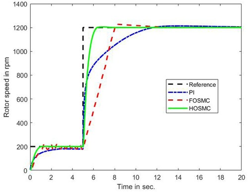
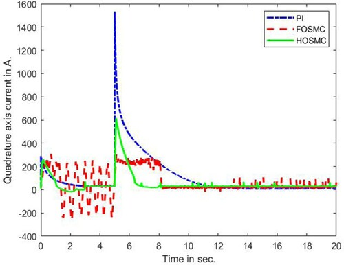
Figure shows the quadrature-axis stator current response to reference-speed and load-torque changes. The first-order SMC causes chattering in tracking the speed response with the load changes and modelling uncertainties, while the higher-order SMC yields a relatively smooth response. The traditional PI-based field-oriented control have the largest q-axis currents, hence the motor drive consumes more electrical power form the battery pack.
Figure 5. Quadrature axis current comparisons.
The direct-axis current is shown in Figure , unlike the traditional PI-based field-oriented control, where is set to be zero, MTPA and MPPA require negative
reference current for maximizing the torque and power output of the interior permanent magnet synchronous motor. The higher-order SMC again shows superior performance over the first-order method by eliminating chattering phenomenon.
Figure 6. Direct-axis current comparisons.
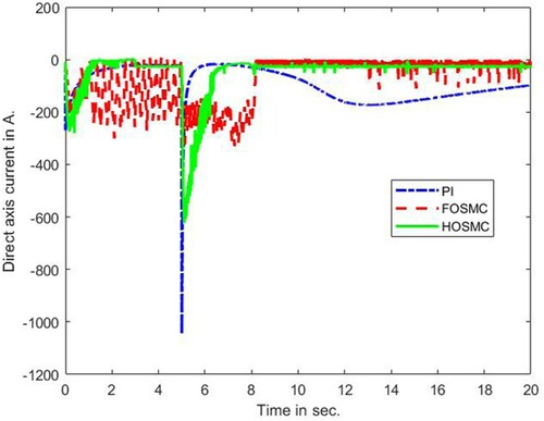
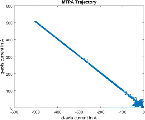
Figure shows the MTPA trajectory with direct-axis current on x-axis and quadrature axis current
on y-axis.
Figure 7. MTPA trajectory.
When the load torque changes, both first-order and higher-order SMC show faster transient responses in comparison with the traditional PI-based field-oriented control scheme. Again, the higher-order SMC reaches the steady-state much faster than the first-order method. The traditional PI-based field-oriented control shows the slowest response time. Both first-order and super-twisting-based second-order controllers show excellent performance, during speed and load torque changes, while the second-order controller demonstrates superior performance in eliminating the chattering phenomenon. On the other hand, the traditional PI controller produces unsatisfactory results under load torque changing and extraneous disturbance conditions, as the gain parameters and
need to be adjusted in accordance with changing load and external disturbances.
7. Conclusions and future work
In this paper, the interior permanent magnet synchronous motors have been modelled in dq synchronous rotating coordinate frame. The direct-axis reference current equation has been derived for MTPA and MPPA performance. Novel sliding-mode-based MTPA and MPPA control approaches for interior permanent magnet synchronous motor have been developed and examined, which have shown superior performance over traditional PI-based field-oriented control. The super-twisting-based second-order SMC shows superior performance over the first-order method, in providing faster transient responses, shorter settling time, and eliminating the chattering phenomenon. For future research work, the proposed control schemes will be applied for electrified vehicle applications to improve the torque/speed regulation, the overall driving experience, controllability, safety and efficiency.
Disclosure statement
No potential conflict of interest was reported by the author(s).
References
- Alnami, H., Pang, C., Papineni, A., & Wang, X. (2021, November). Optimal interior mounted permanent magnet synchronous motors MTPA and MPPA control based on sliding mode approaches. In Proc. of the 2021 ASME international mechanical engineering congress and exposition (IMECE), on-line, 2021, IMECE2021-70904.
- Krause, P., Wasynczuk, O., Sudhoff, S., & Pekarek, S. (2013, June). Analysis of electric machinery and drive systems(3rd ed.). IEEE Press.
- Levant, A., & Fridman, L. (2002). Higher order sliding modes. In In J. P. Barbot and W. Perruguetti, Sliding mode control in engineering (pp. 53–101). Marcel Dekker.
- Morimoto, S., Hatanaka, K., Tong, Y., Takeda, Y., & Hirasa, T. (1993, April). Servo drive system and control characteristics of salient pole permanent magnet synchronous motor. IEEE Transactions on Industry Applications, 29(2), 338–343. https://doi.org/https://doi.org/10.1109/28.216541
- Morimoto, S., Hatanaka, K., Tong, Y., Takeda, Y., & Hirasa, T. (1994, October). Loss minimization control of permanent magnet synchronous motor drives. IEEE Transactions on Industry Applications, 41(5), 920–926. https://doi.org/https://doi.org/10.1109/28.297908
- Morimoto, S., Sanada, M., & Takeda, Y. (1994, August). Wide-Speed operation of interior permanent magnet synchronous motors with high-performance current regulator. IEEE Transactions on Industry Applications, 30(4), 511–517. https://doi.org/https://doi.org/10.1109/28.297908
- Morimoto, S., Takeda, Y., & Hirasa, T. (1990a, April). Current phase control methods for permanent magnet synchronous motors. IEEE Transactions on Power Electronics, 5(2), 133–139. https://doi.org/https://doi.org/10.1109/63.53150
- Morimoto, S., Takeda, Y., & Hirasa, T. (1990b, October). Expansion of operating limits for permanent magnet motor by current vector control considering inverter capacity. IEEE Transactions on Industry Applications, 26(5), 866–871. https://doi.org/https://doi.org/10.1109/28.60058
- Uddin, M. N., Radwan, T. S., & Rahman, M. A. (2002, March). Performance of interior permanent magnet drive over wide speed range. IEEE Transactions on Energy Conversion, 17(1), 79–84. https://doi.org/https://doi.org/10.1109/60.986441
- Utkin, V., Young, K., & Ozguner, U. (1999, May). A control engineer's guide to sliding mode control. IEEE Transactions on Control Systems Technology, 7(3), 328–342. https://doi.org/https://doi.org/10.1109/87.761053
- Wang, X., Reitz, M., & Gu, P. (2016, June). (2016). Robust sliding mode control of permanent magnet synchronous motor drive. In: Proc. of the 2016 IEEE Transportation electrification conference & expo. Dearborn, MI, June 27–29.
- Wang, X., Reitz, M., & Yaz, E. E. (2018, November). Field oriented sliding mode control of surface-Mounted permanent magnet AC motors: theory and applications to electrified vehicles. IEEE Transactions on Vehicular Technology, 67(11), 10343–10356. https://doi.org/https://doi.org/10.1109/TVT.2018.2865905
- Xu, Z., & Rahman, M. F. (2003, November). Sensorless sliding mode control of an interior permanent magnet synchronous motor based on extended Kalman filter. The Fifth International Conference on Power Electronics and Drive Systems (Vol. 1, pp. 722–727). Singapore.