
 ?Mathematical formulae have been encoded as MathML and are displayed in this HTML version using MathJax in order to improve their display. Uncheck the box to turn MathJax off. This feature requires Javascript. Click on a formula to zoom.
Abstract
A gaze control system for tracking Quasi-1D high-speed moving object is proposed, it can keep the object in the centre of the image within a certain range. Initially, the system structure is designed, and the tracking range of the system is expanded using a single saccade mirror. Then the model between the deflection angle of the saccade mirror and the pixel displacement is established. Finally, a frame-difference method based on image cropping is proposed to rapidly extract the moving object in the complex dynamic background. It feeds back the object position to the saccade mirror control system. The system adjusts the deflection angle of the saccade mirror in real time. Experimental results show that the system can satisfy the requirements of gaze control for tracking Quasi-1D high-speed moving object.
1. Introduction
High-speed moving objects are widely used in the fields of national defence, aerospace and sports events. Vision measurement method has gradually become the mainstream method for the analysis of high-speed moving objects because of its characteristics of no load effect (Mehta et al., Citation2019). However, the accurate measurement of the moving object body requires the object to occupy as many pixels as possible, as well as a large focal length, resulting in a small field of view. The long-time measurement of the moving object trajectory requires the field of view to be as large as possible, resulting in the small focal length requirement, a contradiction exists between the two approaches. The emergence of the gaze control system solves this contradiction. A high-speed camera uses a large focal length to make the object body as clear as possible. The long-time tracking can be realized in a large area by changing the camera's field of view. The real-time performance of the gaze control system determines the fastest motion speed of the object that can be tracked. The real-time performance of the gaze control system is limited by many factors, such as the speed of the visual object tracking method and the rotational inertia of the saccade mirror, among which the speed of the visual object tracking method is the decisive factor.
Traditional gaze control system uses an active vision system (PTZ camera) to obtain images in a wider range of viewing angles. However, the high-speed rotation performance of the camera limits the development of visual servo systems (Jonnalagadda & Elumalai, Citation2021). Okumura et al. (Citation2011) developed a high-speed visual gaze controller using two rotating mirrors, which replaced camera rotation with saccade mirror rotation, a major breakthrough in the history of visual servo systems. In Okumura et al. (Citation2015) added two cameras on the basis of the original high-speed visual gaze controller, which can not only process images at a high frame rate but also observe with high resolution thus, the robustness of the dual saccade mirror system is improved. The dual saccade mirror system can track moving objects in two dimensions. However, due to structural reasons, the scope of rotation of saccade mirror is limited, and the imaging and scanning angles are small.
The visual object tracking method is a decisive factor affecting the real-time performance of gaze control system. Methods based on correlation filtering and deep learning (Y. Chen et al., Citation2020; Z. Chen et al., Citation2020; Feng et al., Citation2018; Guo et al., Citation2020; Li et al., Citation2020; Liu et al., Citation2019; Lukezic et al., Citation2020; Moorthy et al., Citation2020; Voigtlaender et al., Citation2020; Xiao et al., Citation2021; Xu et al., Citation2020; Zhang & Peng, Citation2020) have gradually become the mainstream methods in the field of visual object tracking. Li et al. (Citation2020) proposed a discriminative correlation filter that automatically adjusts the hyperparameters of the space-time regular term, which can mitigate the boundary effects and filter degradation on the tracking performance at a speed of approximately 60 fps. SiamBAN (Z. Chen et al., Citation2020) used the Siamese network to directly classify objects and regress their bounding boxes, with a speed of approximately 40 fps. SiamCAR (Guo et al., Citation2020) used the Siamese network for the feature extraction module and classification regression and added the centre degree branch. The speed is approximately 170 fps when using AlexNet network architecture. The visual object tracking methods based on correlation filtering and deep learning need to obtain the prior knowledge of the object to be tracked in the region of interest of the initial frame to realize the object tracking in the subsequent frames. Therefore, these two methods are difficult to apply in the real-time tracking situation.
Methods that do not rely on the initial frame region of interest include optical flow (Ilg et al., Citation2017; Song et al., Citation2021; Vihlman & Visala, Citation2020), background modelling (Guo et al., Citation2019; Verma et al., Citation2021; Zhou et al., Citation2020), and frame-difference (Bai et al., Citation2019; Gao & Lu, Citation2019; Husein & Leo, Citation2019; Zhang, Citation2020; Zheng, Citation2021). The optical flow method needs to calculate the optical flow of each feature point in the region, and the speed is slow. FlowNet2.0 (Ilg et al., Citation2017) combined the optical flow method with a neural network to transform the optical flow estimation into a learning problem, and the tracking speed is increased to approximately 140 fps. In view of the problem of background fluctuation, Zhou et al. (Citation2020) proposed the Marine background modelling method of Mixed Gaussian background Fourier domain (FGMM), which improved the anti-interference performance of the traditional spatial mixed Gaussian background modelling algorithm. Gao and Lu (Citation2019) proposed a two-frame difference method based on texture features and colour features, which can be used for moving target detection under small disturbance background. Zhang (Citation2020) combined the frame difference method with edge information to achieve high-precision moving target detection. The frame-difference method has a simpler principle and faster operation speed than the optical flow method and background modelling method, it is widely used in static background tracking. When the background changes due to the motion of the camera field of view, the traditional frame-difference method cannot distinguish the moving object from the static background. Therefore, it cannot be directly applied to gaze control system.
In view of this analysis, a gaze control system for tracking Quasi 1D high-speed moving object is designed. The so-called Quasi 1D high-speed moving object refers to the object moving at high speed in the horizontal direction and ignoring the free fall introduced by gravity within a certain range, such as a horizontally fired shell or bullet. The innovation of this paper lies in the single saccade mirror can effectively expand the tracking range of the system. The improved frame-difference method can be used to calculate the position of the object in the picture in real time, and the position can be fed back to the saccade mirror control system to realize the real-time gaze control for tracking Quasi 1D high-speed moving object. The observation range of gaze tracking system determines whether the whole movement process can be observed completely, and real-time performance determines whether the high-speed moving object can be tracked. Therefore, it is of great engineering practical significance to expand the observation range of gaze tracking system and improve the real-time performance of gaze tracking system.
The second section designs the system structure. In Section 3, the model of the relationship between the rotation angle of saccade mirror and the motion displacement of pixels in the image plane is established. In Section 4, the visual tracking method of moving object in the complex dynamic background is studied. In Section 5, the validity of the proposed system is verified by experiments. Section 6 summarizes the research achievements and contributions of this study.
2. System structure design
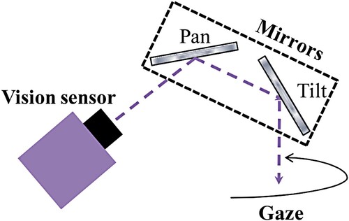
The dual saccade mirror system (Figure ) adopts the translation saccade mirror and tilt saccade mirror. First, the tilt saccade mirror rotates to reflect the motion of the moving object in the vertical direction, and then the horizontal motion of the moving object in the mirror of the tilt saccade mirror is reflected by rotating the translation saccade mirror. Therefore, the dual saccade mirror system can track a moving object in two dimensions. However, the imaging and maximum scanning angles of the dual saccade mirror system are limited due to the structure.
Figure 1. Dual saccade mirror system (Okumura et al., Citation2011).
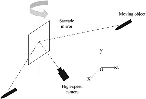
In view of the motion characteristics of the Quasi-1D high-speed moving object, the proposed system adopts the single saccade mirror mode and only requires the translation saccade mirror, which can achieve a larger imaging angle and scanning angle. The system structure is shown in Figure . The centre point of the saccade mirror is considered the origin of the coordinate system, the object motion trajectory is the -axis (the motion direction is set as the positive direction), the rotation axis of the saccade mirror is the
-axis (the upward direction is set as the positive direction), and the orthogonal axis with
plane is the
-axis (the direction from the saccade mirror to the object is set as the positive direction).
Figure 2. The structure of our system.
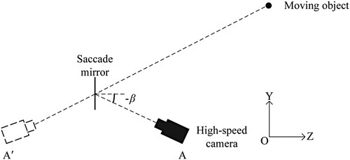
The camera is placed in the plane, with a fixed position, and the object is photographed through the reflection of the saccade mirror. In order to avoid the occlusion caused by the camera body, the camera is placed below the object trajectory, and the angle between the camera perspective and the
axis is
. According to the principle of mirror imaging, position A of the solid camera can be equivalent to position
of the virtual camera in the mirror, as shown in Figure .
Figure 3. Left view of our system.
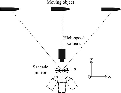
When the saccade mirror rotates around the -axis, the camera's field of view is translated in the X-axis direction. The angle between the mirror and the XOY plane is set as α, the positive angle is set for counterclockwise rotation and the negative angle for clockwise rotation. The rotation angle is determined in accordance with the object position to realize the change in the camera's field of view to ensure that the object is always in the centre of the picture. The principle is shown in Figure .
Figure 4. Top view of our system.
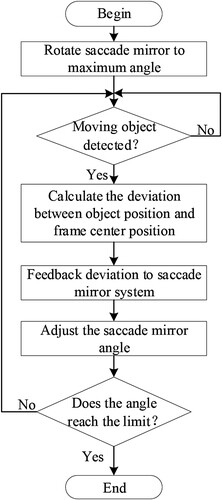
The system operation flowchart is shown in Figure . The system first places the saccade mirror at the corresponding maximum deflection angle according to the direction of the object. The high-speed camera is started to collect images in real time and detect whether moving objects appear in continuous images. When the moving object is detected, the deviation between the position of the object in the picture and the centre point of the picture is calculated and fed back to the saccade mirror control system to form a closed-loop control. Thus, gaze control is achieved for tracking high-speed moving object. By using elevation shooting mode, the system can obtain a larger observation range.
Figure 5. System operation flow chart.
3. System modelling
According to the system structure, when the saccade mirror rotates around the -axis, the camera's field of view can be translated along the X-axis. The model between the saccade mirror rotation angle and the picture translation pixel can be established through the transformation of the world coordinate system, camera coordinate system, imaging coordinate system and pixel coordinate system (Zhu et al., Citation2020).
3.1. Coordinate system transformation
The position of the object at a point in the world coordinate system is set as and the corresponding coordinate in the pixel coordinate system as
. Zhang Zhengyou calibration method is presented as follows (Zhang, Citation1999):
(1)
(1)
where R represents the Camera Extrinsic-Matrix, and
constitutes the rotation matrix, representing the rotation relationship between the world coordinate system and the camera coordinate system.
,
and
represent the translation relationship between the world coordinate system and the camera coordinate system. A represents the Camera Intrinsic-Matrix, which means affine transformation relationship between the pixel coordinate system and the camera coordinate system. f refers to the focal length of the camera. 1/dx and 1/dy represent the scaling transformation factor of the two axes between the imaging coordinate system and the pixel coordinate system, respectively.
and
represent the coordinate components of the origin of the pixel coordinate system in the imaging coordinate system.
represents the
-axis coordinates of the point in the camera coordinate system. R and A can be obtained by the camera calibration toolbox in Matlab. In the process of system gaze control tracking, the Intrinsic-Matrix A is fixed and the Extrinsic-Matrix R changes with the change in the saccade mirror angle.
3.2. Scale relationship between the coordinate systems
The system needs to complete camera calibration in the initialization stage. The camera was calibrated when the deflection angle of the saccade mirror . Zhang Zhengyou calibration method (Zhang, Citation1999) was adopted, and the camera calibration toolbox of Matlab was used as the calibration tool. The world coordinates of the two adjacent corner points in the horizontal direction of the checkerboard are assumed to be
and
, and the
-axis coordinates of all points on the checkerboard is assumed to be 0. The pixel position of
is calculated using Equation (Equation1
(1)
(1) ), as follows:
(2)
(2)
Similarly, the pixel position
can be calculated as follows:
(3)
(3)
Thus, the distance between the two coordinate points in the pixel coordinate system in the horizontal and vertical directions is obtained:
(4)
(4)
Let the checkerboard size in the world coordinate system be
; thus, the pixel length p corresponding to 1 mm in the world coordinate system is calculated as follows:
(5)
(5)
3.3. Conversion of saccade mirror rotation angle and horizontal displacement pixel of camera gaze line
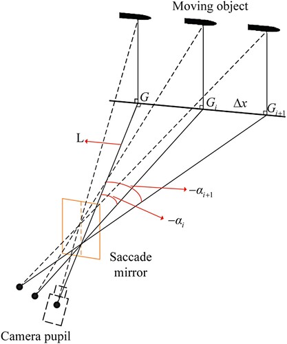
The relationship between the saccade mirror rotation angle and the horizontal displacement of the camera gaze line is calculated in the world coordinate system, as shown in Figure . The dotted line represents the camera gaze line. Suppose that and
are the two deflection angles of saccade mirror, and the corresponding points of the camera gaze line projected on the
plane are
and
. According to the mirror imaging principle, the gaze lines of different angles intersect at the central point of the saccade mirror. L represents the distance between the saccade mirror centre point and the projection point G of the camera gaze line on the
plane when the saccade mirror deflection angle is
. According to the geometric relation, the horizontal displacement of the camera gaze line is equal to the distance between its projections
and
on the
plane:
(6)
(6)
According to Equation (Equation5
(5)
(5) ), the scale transformation relationship between the world coordinate system and the pixel coordinate system is derived. Combining Equations (Equation5
(5)
(5) ) and (Equation6
(6)
(6) ), the relationship between the deflection angle of the saccade mirror and the horizontal pixel displacement of the camera gaze line is calculated as follows:
(7)
(7)
Equation (Equation7
(7)
(7) ) is the camera field motion model. According to this model, it is possible to calculate the position in the image of any point in the world coordinate system by the deflection angle of the mirror.
Figure 6. Saccade mirror rotation angle and object movement displacement.
4. Moving object tracking method in complex dynamic background
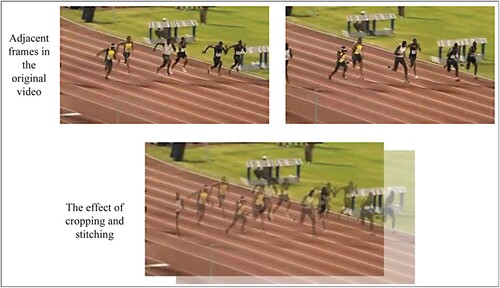
The frame-difference method has a simple principle and fast operation speed. The basic idea is to mark the moving object by differential operation of two adjacent frames in the video. However, the premise of using the frame-difference method is that the camera's field of view remains fixed. If the camera field of view changes, such as the gaze control system, the originally static background becomes dynamic in successive frames, and the frame-difference method cannot distinguish the moving object from the background. An improved frame-difference method based on image cropping (Zeng et al., Citation2019) is put forward; it uses the known gaze system saccade mirror deflection angle calculation between two adjacent frames on the pixel coordinates of offset and crops the parts with different edge positions of the two frames to ensure that the static background on the two adjacent frames in the same pixel position to distinguish between the moving object and background.
4.1. Frame-difference method based on image cropping
Suppose w represents the width of the image and h represents the height of the image. As long as the pixel point of position in the nth frame corresponds to the position
in the
th frame, the frame difference method can be used to detect the moving object in the image. Assuming that the gaze line of the camera in
th frame is shifted by
pixels to the right and
pixels to the down relative to nth frame, the relationship between
and
can be obtained as follows:
(8)
(8)
where,
,
,
, and
; the value range is set to ensure that no boundary overflows during the calculation. Therefore, according to the value ranges of
and
, the image of the nth frame and the image of the
th frame should be cropped, and the pixel points of the
th to the wth column and the
th to the hth line of the image of the nth frame are retained. However, the pixel points of the first to
th column and the first to
th line of the image of the
th frame are retained. This processing method can completely eliminate the offset of the static background on the image caused by the camera gaze line movement, as shown in Figure . The size of the two frame images, which were cropped, is no longer
, but
.
Figure 7. Cropping effect of two adjacent frames in the Bolt video.
Assuming that represents the grey value of
pixel on the nth frame image in the video sequence (with the upper left corner as point
), the difference formula (Zheng, Citation2021) of any adjacent frame image is shown as follows:
(9)
(9)
where,
is the absolute value of the difference image of the next frame minus the current frame image. Let T be the threshold and
be the difference graph. Then,
can be determined by the following formula:
(10)
(10)
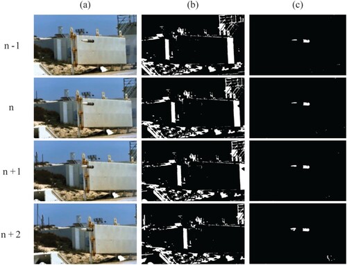
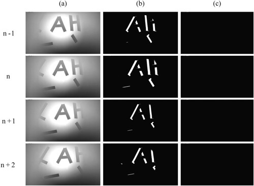
The validity of the proposed method is verified by taking a video of gaze control for tracking a projectile published on the Internet as the object. Figure (a) shows the
th, nth,
th and
th frames of the video. The figure shows that: 1) the camera gaze line is always moving in the direction of the projectile movement; 2) the background is complex, with large interference. Figure (b) shows the difference image of the traditional frame-difference method, and Figure (c) shows the difference image based on the cropping frame-difference method. The findings indicate that the traditional frame-difference method is completely unable to detect the moving projectile, but the improved method can effectively detect the position of the moving projectile.
Figure 8. Tracking results of the projectile video; (a) Sequence of four consecutive frames in the video, (b) Tracking results of traditional frame-difference method, (c) Tracking results of the method in this paper.
The simulation experiment platform is PC (CPU: i7-4790, memory: 16GB, software: Matlab R2018a). Table shows the comparison between the proposed method and other mainstream methods, such as background subtraction, optical flow, correlation filtering and deep learning in terms of computing speed (although correlation filtering and deep learning cannot be used in real-time situations because they need the region of interest on the first frame). The comparison results show that the frame-difference method based on cropping is second only to the traditional frame-difference method in the calculation speed and has a more evident speed advantage than other mainstream target tracking methods.
Table 1. Speed comparison of target tracking methods.
5. Experiments
5.1. Verification experiment of visual method
A Quasi-1D high-speed moving object gaze control system is proposed to calculate the amount of cropping between two adjacent frames by means of the deflection angle of the saccade mirror. A complex background was set in a laboratory environment and the saccade mirror was deflected at a preset speed to verify the effectiveness of the method. In addition, a high-speed camera was used to capture images. During the entire shooting, the background is fixed in the world coordinate system and no moving object appears. The experimental environment is shown in Table .
Table 2. Experimental-related equipment and parameters.
As shown in Figure , although the static background in the world coordinate system presents the translation effect in the video sequence, the proposed method can effectively match the pixel position of a certain background pixel in the previous frame on the current frame, regardless the complexity of the background. The traditional frame-difference method completely regards the moving background in the video sequence as the moving object in the world coordinate system.
Figure 9. Experimental results; (a) Four consecutive images taken by the camera, (b) Tracking results of traditional frame-difference method, (c) Tracking results of the method in this paper.
5.2. System verification experiment
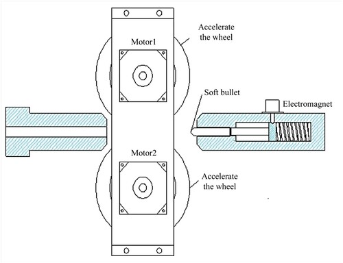
Considering the safety problem, the experimental object is a soft toy bullet made of EVA material with Quasi-1D high-speed movement. According to the geometric relationship in the Ballistic Analysis scene, the semi-physical experimental platform can be built after equal scale reduction. The research group has designed and developed a set of launching device, whose structure is shown in Figure . The radius of the accelerating wheel is 0.1 m, and the speed is 10000 r/min. The soft bullet can obtain an initial velocity of approximately 100m/s by pushing the spring and squeezing the two accelerating wheels.
Figure 10. Launcher.
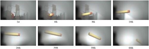
The shooting range of the experiment is 39.4 (optical angle). The object movement speed is approximately 100m/s. As shown in Figure , the proposed system can effectively track the Quasi-1D high-speed moving object.
Figure 11. Gaze control for tracking a soft toy bullet uses our system.
6. Conclusions
A Quasi-1D high-speed moving object gaze control system is designed and studied from two aspects of structural design and method improvement. In the structural design, the single saccade mirror is adopted to solve the problem of limited perspective and tracking range of the traditional dual saccade mirror. In terms of method improvement, the frame-difference method based on cropping is adopted to solve the problem, that is, the traditional frame-difference method cannot be applied in the dynamic field of view. In addition, the method has evident advantages over other mainstream object tracking methods. The effectiveness of the system is verified by experiments in the laboratory. For future work, we consider improving the tracking accuracy of the system to ensure that the object is not only always in the picture but also in the centre of the picture.
Disclosure statement
No potential conflict of interest was reported by the authors.
Data availability statement
Data sharing is not applicable to this article as no new data were created or analysed in this study.
Additional information
Funding
References
- Bai, Z., Gao, Q., & Yu, X. (2019). Moving object detection based on adaptive loci frame difference method. In 2019 IEEE International Conference on Mechatronics and Automation (ICMA) (pp. 2218–2223). https://doi.org/10.1109/ICMA.2019.8816624.
- Chen, Y., Xu, J., Yu, J., Wang, Q., Yoo, B., & Han, J. J. (2020). AFOD: Adaptive focused discriminative segmentation tracker. Proceedings of the 16th European Conference on Computer Vision (ECCV 2020), 12539, 666–682. https://doi.org/10.1007/978–3-030–68238-544.
- Chen, Z., Zhong, B., Li, G., Zhang, S., & Ji, R. (2020). Siamese box adaptive network for visual tracking. In 2020 IEEE/CVF Conference on Computer Vision and Pattern Recognition (CVPR) (pp. 6667–6676). https://doi.org/10.1109/CVPR42600.2020.00670.
- Feng, F., Shen, B., & Liu, H. J. (2018). Visual object tracking: In the simultaneous presence of scale variation and occlusion. Systems Science and Control Engineering, 6(1), 456–466. https://doi.org/10.1080/21642583.2018.1536899.
- Gao, F., & Lu, Y. (2019). Moving target detection using inter-frame difference methods combined with texture features and lab color space. In 2019 International Conference on Artificial Intelligence and Advanced Manufacturing (AIAM) (pp. 76–81). https://doi.org/10.1109/AIAM48774.2019.00022.
- Guo, D., Wang, J., Cui, Y., Wang, Z., & Chen, S. (2020). SiamCAR: Siamese fully convolutional classification and regression for visual tracking. In 2020 IEEE/CVF Conference on Computer Vision and Pattern Recognition (CVPR) (pp. 6268–6276). https://doi.org/10.1109/CVPR42600.2020.00630.
- Guo, Z., Dang, J., Wang, Y., & Jin, J. (2019). Background modeling algorithm for multi-feature fusion. In 2019 Asia-Pacific Signal and Information Processing Association Annual Summit and Conference (APSIPA ASC) (pp. 1117–1121). https://doi.org/10.1109/APSIPAASC47483.2019.9023315.
- Husein, A. M., & Leo, R. (2019). Motion detect application with frame difference method on a surveillance camera. Journal of Physics Conference Series, 1230(1), 1–10. https://doi.org/10.1088/1742–6596/1230/1/012017.
- Ilg, E., Mayer, N., Saikia, T., & Keuper, M. (2017). FlowNet 2.0: Evolution of optical flow estimation with deep networks. 2017 IEEE/CVF Conference on Computer Vision and Pattern Recognition (CVPR), 2(6), 2462–2470. https://doi.org/10.1109/CVPR.2017.179.
- Jonnalagadda, V. K., & Elumalai, V. K. (2021). Hardware-in-the-loop testing of current cycle feedback ILC for stabilisation and tracking control of under-actuated visual servo system. International Journal of Systems Science, 52(5), 1042–1060. https://doi.org/10.1080/00207721.2020.1853273.
- Li, Y., Fu, C., Ding, F., Huang, Z., & Lu, G. (2020). AutoTrack: Towards high-performance visual tracking for UAV with automatic spatio-temporal regularization. In 2020 IEEE/CVF Conference on Computer Vision and Pattern Recognition (CVPR) (pp. 11920–11929). https://doi.org/10.1109/CVPR42600.2020.01194.
- Liu, J., Luo, Z., & Xiong, X. (2019). An improved correlation filter-based target tracking method. In 2019 IEEE 4th International Conference on Signal and Image Processing (ICSIP) (pp. 219–223). https://doi.org/10.1109/SIPROCESS.2019.8868811.
- Lukezic, A., Matas, J., & Kristan, M. (2020). D3S–a discriminative single shot segmentation tracker. In 2020 IEEE/CVF Conference on Computer Vision and Pattern Recognition (CVPR) (pp. 7133–7142). https://doi.org/10.1109/CVPR42600.2020.00716.
- Mehta, S. S., Ton, C., Rysz, M., & Curtis, J. W. (2019). New approach to visual servo control using terminal constraints. Journal of the Franklin Institute, 356(10), 5001–5026. https://doi.org/10.1016/j.jfranklin.2019.04.026.
- Moorthy, S., Jin, Y. C., & Joo, Y. H. (2020). Gaussian-response correlation filter for robust visual object tracking. Neurocomputing, 411(3), 78–90. https://doi.org/10.1016/j.neucom.2020.06.016.
- Okumura, K., Oku, H., & Ishikawa, M. (2011). High-speed gaze controller for millisecond-order pan/tilt camera. In IEEE International Conference on Robotics and Automation (pp. 6186–6191). https://doi.org/10.1109/ICRA.2011.5980080.
- Okumura, K., Yokoyama, K., Oku, H., & Ishikawa, M. (2015). 1ms auto pan-tilt–video shooting technology for objects in motion based on saccade mirror with background subtraction. Advanced Robotics, 29(7), 457–468. https://doi.org/10.1080/01691864.2015.1011299.
- Song, T., Cao, L. B., Zhao, M. F., Luo, Y. H., Yang, X., & Liu, S. (2021). Image tracking and matching algorithm of semi-dense optical flow method. International Journal of Wireless and Mobile Computing, 20(1), 93–98. https://doi.org/10.1504/IJWMC.2021.113228.
- Verma, K., Ghosh, D., Singh, H., Bisht, S., Ansari, Z. A., Marathe, R., & Kumar, A. (2021). Robust visual tracking with occlusion handling using gaussian mixture modeling. In Proceedings of the International Conference on Optics and Electro-Optics (Vol. 258, pp. 333–336). https://doi.org/10.1007/978–981-15–9259-175.
- Vihlman, M., & Visala, A. (2020). Optical flow in deep visual tracking. Proceedings of the AAAI Conference on Artificial Intelligence, 34(7), 12112–12119. https://doi.org/10.1609/aaai.v34i07.6890.
- Voigtlaender, P., Luiten, J., Torr, P., & Leibe, B. (2020). Siam R-CNN: Visual tracking by re-detection. In 2020 IEEE/CVF Conference on Computer Vision and Pattern Recognition (CVPR) (pp. 6578–6588). https://doi.org/10.1109/CVPR42600.2020.00661.
- Xiao, F., Wu, Q., & Huang, H. (2021). Single-scale siamese network based RGB-D object tracking with adaptive bounding boxes. Neurocomputing, 451, 192–204. https://doi.org/10.1016/j.neucom.2021.04.016.
- Xu, T., Feng, Z. H., Wu, X. J., & Kittler, J. (2020). AFAT: Adaptive failure-aware tracker for robust visual object tracking. In 2020 IEEE/CVF Conference on Computer Vision and Pattern Recognition (CVPR) (pp. 1–17).
- Zeng, H., Li, L., Cao, Z., & Zhang, L. (2019). Reliable and efficient image cropping: A grid anchor based approach. In 2019 IEEE/CVF Conference on Computer Vision and Pattern Recognition (CVPR) (pp. 5942–5950). https://doi.org/10.1109/CVPR.2019.00610.
- Zhang, Z. (1999). Flexible camera calibration by viewing a plane from unknown orientations. Seventh IEEE International Conference on Computer Vision, 1, 666–673. https://doi.org/10.1109/ICCV.1999.791289.
- Zhang, Z. (2020). Using three-frame difference algorithm to detect moving objects. Advances in Intelligent Systems and Computing, 928, 923–928. https://doi.org/10.1007/978–3-030–15235-2123.
- Zhang, Z., & Peng, H. (2020). Object-aware anchor-free tracking. In Proceedings of the 16th European Conference on Computer Vision (ECCV 2020) (Vol. 12366, pp. 771–787). https://doi.org/10.1007/978–3-030–58589-146.
- Zheng, D. (2021). Deep learning-driven Gaussian modeling and improved motion detection algorithm of the three-frame difference method. Mobile Information Systems, 2021(15), 1–7. https://doi.org/10.1155/2021/9976623.
- Zhou, A., Xie, W., & Pei, J. (2020). The maritime infrared target detection based on mixture Gaussian background modeling in the Fourier domain. In Automatic Target Recognition and Navigation (p. 11429). https://doi.org/10.1117/12.2535703.
- Zhu, H., Li, Y., Liu, X., Yin, X., Shao, Y., Qian, Y., & Tan, J. (2020). Camera calibration from very few images based on soft constraint optimization. Journal of the Franklin Institute, 357(4), 2561–2584. https://doi.org/10.1016/j.jfranklin.2020.02.006.