
 ?Mathematical formulae have been encoded as MathML and are displayed in this HTML version using MathJax in order to improve their display. Uncheck the box to turn MathJax off. This feature requires Javascript. Click on a formula to zoom.
Abstract
An input shaper-based model predictive control scheme is proposed for an overhead crane to suppress the swing of the payload. A control-oriented mathematical model of the crane is firstly derived based on the small angle hypothesis. Furthermore, three kinds of commonly used shapers are discussed and a zero vibration derivative shaper is selected for the crane. Then, a model predictive swing suppression controller is designed for the crane based on the selected shaper. Constraints on the control input and its slew rate are respected. Besides, the constraint on the swing angle of the payload is also respected as an output constraint. The constrained solution is given in the form of standard quadratic programming. The designed control scheme combines open-loop and closed-loop control techniques, achieving accurate positioning of the trolley and good swing suppression of the payload. A series of simulation demonstrates the effectiveness and advantages of the proposed scheme.
1. Introduction
As a typical representative of crane systems, the overhead crane has the merits of simple structure, high load capacity and convenient operation, etc., widely used in cargo transportation in factories and ports (Ramli et al., Citation2017). For a specific transportation task, the control of a crane mainly includes hoisting, horizontally transporting and lowering. The hoisting and lowering are vertical operations which are easier to implement, while the horizontally transporting is the most challenging. This is because it is closely related to the positioning of the trolley and the swing of the payload.
The main objective of the horizontal transportation phase is that the trolley reaches a desired position as soon as possible while the swing angle of the payload is as small as possible. Clearly, it is a conflict between the fast positioning and the small swing angle, which needs to be considered comprehensively. However, due to physical and economic reasons, most of payloads are usually not controlled directly but dragged by trolleys, which makes crane dynamics underactuated (Aguiar et al., Citation2021). Not only the actuated part should be controlled, but also the underactuated part should be balanced, which puts forward high requirements for the controller design.
The control of overhead cranes has attracted the wide attention of researchers in the communities of mechatronics and control. A great quantity of techniques are available in the literature, and they can be divided into open-loop and closed-loop ones according to the use of information. Open-loop control techniques only need system model information and do not need additional measuring devices, so they are simpler and easier to implement in practice. Input shaping is the most commonly used open-loop control technique in crane swing suppression, proposed by Singer and Seering (Citation1990). This technique fully considers the physical and vibration characteristics of a system, so that the vibration modes in the system are not excited by the input signal, thus the vibration of the system is suppressed fundamentally.
An input shaping control scheme was developed for a crane system, providing additional flexibility in selecting the manoeuvering time and choosing an arbitrary number of inputs through a new optimization technique (Alghanim et al., Citation2019). In order to increase the design flexibility and the operational domain, a modified zero vibration input shaping technique was presented in the work (Mohammed et al., Citation2020), where new parameters were introduced to optimize the system performance. The results show that the modified shaper makes the crane system control powerful and efficient. In the work (Maghsoudi et al., Citation2019), a unity magnitude zero vibration shaper was improved and then applied to a three dimensional overhead crane with hoisting effects. The results show more swing reduction can be achieved due to the high adaptability of the shaper.
As is known to all, due to the lack of feedback mechanism, the performance of open-loop control systems often deteriorates in the face of uncertainties. Therefore, it is necessary to use closed-loop crane control techniques to enhance the robustness of systems. Based on the modified system output, an adaptive control law was developed to a three degree-of-freedom overhead crane in the work (Shen et al., Citation2021). An adaptive anti-swing control strategy was proposed for gantry cranes with desired performance, ensuring that the position error and the swing angle asymptotically converge to the origin (Huang et al., Citation2021). In order to enhance the robustness of systems, both moving sliding mode and fractional-order terminal sliding mode control techniques were used to design controllers for the crane systems (Cuong et al., Citation2021; Gu & Xu, Citation2022). Additionally, techniques such as fuzzy control (Aguiar et al., Citation2021; Sun et al., Citation2021), PID control (Esleman et al., Citation2021; Mohamed et al., Citation2022) and optimal control (Shi et al., Citation2022; Takahashi et al., Citation2022) were also applied in the overhead crane control.
However, many works mentioned above do not fully take into account the physical constraints of crane systems, such as amplitude and swing angle limits. Respecting system constraints is an important way to ensure the actual operation performance and the system security (Elmorshedy et al., Citation2021; Hu et al., Citation2021; Schwenzer et al., Citation2021). Model predictive control (MPC) has a strong ability to deal with constraints, and it can find the optimal solution of a performance function on the premise of satisfying the constraints (Gao et al., Citation2018; Rodriguez et al., Citation2021). And its receding horizon optimization and feedback correction mechanism make the closed-loop system very robust (Tang et al., Citation2017). Therefore, MPC is a promising technique for high-performance crane control.
The constraints in an overhead crane system can be divided into two categories, one is related to the trolley including constraints on the input, the input slew rate, the position, velocity and acceleration of the trolley; the other is related to the payload including constraints on the swing angle, the swing deflection and the velocity of the rope length change. In the work (Jolevski & Bego, Citation2015), the saturation function was used to deal with input constraints, but the resulting control law may not be an optimal solution. According to the recursive feasibility and the definition of input constraint tightening, the input constraint was satisfied in a crane stochastic predictive control system (Hewing & Zeilinger, Citation2019). For the crane motion control system with a DC motor as the actuator, constraints on the input voltage and its slew rate were respected in time optimal model predictive control (Van den Broeck et al., Citation2011). Besides, other constraints on the position and the velocity of the trolley could be considered in the design of model predictive controllers (Giacomelli et al., Citation2018; Khatamianfar & Savkin, Citation2014).
Using a constraint substitution, the constraint on the velocity of the rope length change was met in a real-time model predictive control framework (Käpernick & Graichen, Citation2013). In addition to the trolley constraints, the payload constraints have also been taken into account in the existing research. Under the generalized predictive control scheme, the payload deflection constraint was handled in the work (Smoczek & Szpytko, Citation2016). In order to ensure the safety of crane systems and improve their production efficiency, the swing angles were limited to a certain range by solving constrained predictive control problems (Chen et al., Citation2016; Wu et al., Citation2015).
In view of the importance of satisfying the swing angle constraint, an active swing suppression control scheme based on input shaping and model predictive control techniques is presented. To the best of the authors’ knowledge, the presented work is the first time to combine the input shaping technique with the model predictive control to design a crane control system. The designed system has both open-loop and closed-loop control characteristics, the open-loop control is used to reduce the swing of the payload, and the closed-loop control is used to improve the robustness of the system. The main contributions of the work are summarized as follows.
The practical control performance is guaranteed. For the point-to-point horizontal motion control, constraints on the input and its slew rate are considered, as well as the constraint on the swing angle. These constraints have a great effect on the control performance, if they can be considered in the controller design stage, it is a guarantee to achieve the desired performance in practice.
The treatment of the swing angle constraint is progressive. Unlike the treatment in the work (Chen et al., Citation2016), the swing angle constraint was finally expressed as an input constraint through complex transformation which may result in a conservative solution, i.e. the obtained input constraint is not equal to the original constraint. Herein, the swing angle is regarded as a new output, and the treatment of the output constraint does not bring any conservatism.
The convenience of solving constrained model predictive control law is achieved. In the work (Wu et al., Citation2015), only the description of the crane model predictive control problem was available, which is not conducive to revealing details of the solution. The output prediction, the performance function and the constraints transformation are available in this work. The designed model predictive control law can be conveniently solved by standard quadratic programming algorithms.
The performance of the positioning and the swing suppression is guaranteed. The proposed control scheme organically integrates open-loop and closed-loop control techniques, aiming at the accurate positioning of the trolley and the swing suppression of the payload, respectively. So the comprehensive performance of the system is firmly guaranteed.
The remainder of this work is arranged as follows. Section 2 describes the overhead crane dynamics. The input shaping technology is introduced in Section 3. In Section 4, the active swing suppression control scheme is presented. Finally, a few remarks are made to conclude the work in Section 5.
2. Overhead crane dynamics
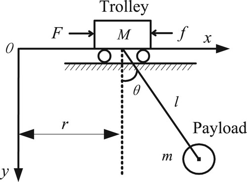
Consider a two-dimensional overhead crane model, as shown in Figure . The Trolley moves along the x-axis, and the payload tied to the trolley through a cable also moves in the same direction. The trolley stops moving when it reaches the desired position, while the payload will make an attenuated swing motion due to its own inertia. Ignoring the viscous friction force of the cable and using Lagranges equations, the dynamic model of this crane system can be given (Wu et al., Citation2009), by.
(1)
(1) where
,
,
,
,
,
,
,
are the trolley mass, the payload mass, the trolley position, the cable length, the payload swing angle with respect to the vertical direction, the frictional force, the driving force and the gravity acceleration, respectively. For the friction force
between the trolley and the track, it can be written as
. As described in (1), the trolley position
and the swing angle
are coupled. Additionally, the swing angle
is also affected by the cable changes
. Herein, the focus is on the swing angle movement during point-to-point motion of the trolley, and there is no hoisting action for the payload, so giving
. As a result, the system (1) can be expressed as
(2)
(2) The derived system (2) is the same as the one in the work (Giacomelli et al., Citation2018), but different from the ones in the works (Chen et al., Citation2016; Wu et al., Citation2015, Citation2020). The difference is that the frictional force
of the trolley is taken into account in (2). It seems to be more reasonable because the surface of the track is not completely smooth, and some uncertainty will be brought to the system when ignoring the friction force. Consider that the swing angle is small and generally varies within several degrees, consequently,
,
. Furthermore,
, So the system (2) can be simplified to.
(3)
(3)
Figure 1. Overhead crane model.
It can be seen from the second equation in (3) that the swing angle can be adjusted by controlling the acceleration of the trolley. Therefore, the key to a controller design is to effectively reduce the acceleration of the trolley, while the acceleration is caused by the position tracking of the trolley. Define the state vector as , the control input as
, the output
, then the (3) can be rearranged in state-space form of
(4)
(4) where
,
,
.
The objective of this work is to design a position controller to make the trolley reach the desired position from the origin as soon as possible. At the same time, the amplitude and the convergence time of the swing angle are as small as possible in the course of motion.
3. Input shaping technology
3.1. Basic principle
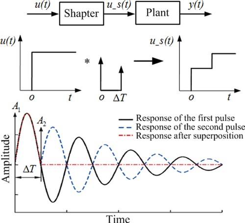
Input shaping is a feedforward filtering technique, which is often used to suppress the residual vibration caused by point-to-point motion of flexible structures (Huseyin Bilgic et al., Citation2021). An input shaper consists of a series of pulses with different amplitudes and delays. The convolution operation between the system input and the pulse sequences generates a new input to drive the system, and the basic principle of a shaper is shown in Figure . In which, a pulse signal with an amplitude of is the input at time
, and its response is represented by a solid line. In order to suppress the vibration excited by the first pulse, a pulse signal with an amplitude of
is another input at time
, and its response is represented by a dashed line. According to the superposition principle of linear systems, the current system response represented by a dash-dotted line is the sum of responses generated by the above two pulses. As long as
,
and
are selected properly, when
, the responses caused by the above two pulses counteracts each other, thus achieving the purpose of vibration suppression.
Figure 2. Principle of input shaping.
Concretely, designing an input shaper requires a series of constraints (Wei et al., Citation2019), including the residual vibration, the robustness, the time optimization and the pulse amplitude. According to the above conditions, the constraint equations about the pulse amplitude and the action time of an input shaper can be solved, from which different shapers can be designed.
3.2. Commonly used shapers
Consider a typical second-order system as follows.
(5)
(5) where
is the natural frequency and
is the damping ratio. Three commonly used shapers are discussed in this section to select one which is more suitable for crane swing suppression. The first one to be discussed is a zero vibration (ZV) shaper which contains two pulses and needs to satisfy the residual vibration, the time optimization and the pulse amplitude constraints (Du et al., Citation2019). The pulse amplitudes and the time lags can be written as
(6)
(6) where
,
. The second one to be discussed is an zero vibration derivative (ZVD) shaper which contains three pulses and needs to satisfy the residual vibration, the robustness, the time optimization and the pulse amplitude constraints (Kang et al., Citation2020). The pulse amplitudes and time lags can be written as
(7)
(7) The third one to be discussed is an extra insensitive (EI) shaper which contains three pulses (Huang et al., Citation2020). The pulse amplitudes and time lags can be written as
(8)
(8) where
is a residual vibration ratio.
In order to verify the swing suppression performance of shapers discussed above, an overhead crane is selected for verification, and its parameters are kg,
kg,
m,
m/s2,
. According to the swing equation in (3), taking
as the input, and then the natural frequency and the damping ratio can be calculated as
and
, respectively. It should be pointed out that the zero damping ratio is determined by the simplified equation, which is not consistent with the actual situation, although the damping ratio is very small. With reference to reference (Van den Broeck et al., Citation2011), the damping ratio is changed to
.
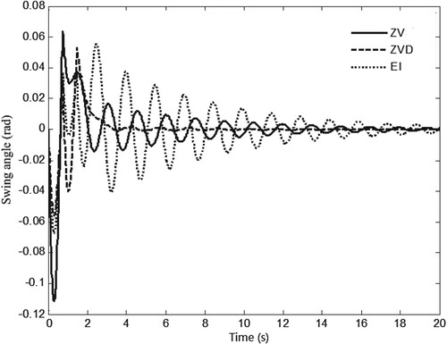
The design of ZV, ZVD and EI shapers can be completed based on the equations of (6), (7) and (8). Setting the desired position of the trolley as m, and the above shapers are applied to the overhead crane system one by one to carry out open-loop control, and the results are shown in Figures and . As shown in Figure , from the initial position to the desired position, there is no significant difference in the horizontal movements of the trolley. However, there is a big difference in the swing angle response, as shown in Figure . It is obvious that the amplitude of the swing angle is the smallest under the ZVD shaper, which shows that the ZVD shaper has the best suppression effect on the swing angle. Therefore, the ZVD shaper will be added to the following crane closed-loop control.
Figure 3. Position response of the trolley.
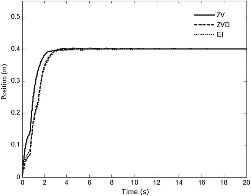
Figure 4. Swing response of the payload.
Remark 3.1:
All the simulations in this paper were carried out by writing m-type files in Matlab 2010b software, in which the fourth-order Runge–Kutta method was used to solve dynamic equations.
4. ZVD shaper-based active swing suppression control scheme
The input shaping technology is an open-loop control algorithm, so it needs to be combined with the feedback control algorithm to enhance the robustness of the closed-loop system. In the following section, two active swing suppression schemes are constructed by combining the shaping technology with PID control and model predictive control algorithms. The PID control algorithm does not need to obtain the dynamic model of a system, so it is easy to implement. While MPC algorithm needs to use the model of a system, obtaining high control performance through the receding horizon optimization and the feedback correction.
4.1. ZVD shaper-based PID swing suppression control
According to the system (3), a double-loop PID control scheme shown in Figure is constructed, in which the outer loop is used for the position control of the trolley and the inner loop is used for the swing angle control of the payload. The ZVD shaper is placed at the output of the position controller. Parameters of the position controller are ,
,
, while parameters of the angle controller are
,
,
. Besides, comparisons between the PID-ZVD control and the ZVD shaper control, the PID control are carried out, the results are shown in Figures and .
Figure 5. Structure of ZVD shaper-based PID control for the crane.
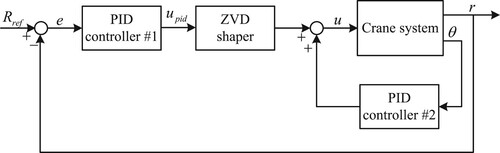
Figure 6. Position response under the different control algorithms.
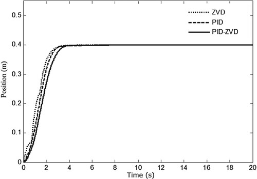
Figure 7. Swing response under the different control algorithms.
Remark 4.1:
Unlike the general shaper-based control, where the shaper is usually connected to the reference signal Rref, the shaper is connected to the position controller. According to the input shaping principle introduced in Section 3.1, it may be more reasonable to connect the shaper to the position controller. Of course, other ways may be used to connect the shaper, such as placing it on the branch of the crane system.
Remark 4.2:
For the selected PID control parameters, they are determined by a large number of simulations based on the role of the parameters. Of course, they are can also be determined based on the parameter setting methods.
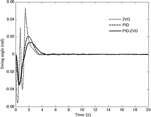
As shown in Figure , the trolley reaches the desired position under these control algorithms, and the dynamic performance is similar. The more obvious difference is the swing angle, as shown in Figure . It is the largest under the ZVD shaper control, it is the smallest under the PID-ZVD control, and it is between the above two cases under the PID control. A conclusion can be drawn that the combination of open-loop and closed-loop control algorithms is helpful to reduce the swing angle. However, the PID-ZVD control effort based on error generation may not be timely for the system. Moreover, this algorithm is easy to cause control input saturation when the error is large.
4.2. ZVD shaper-based model predictive swing suppression control
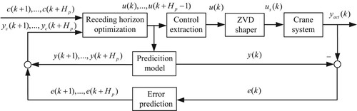
In order to further reduce the residual swing of the payload, a combination of ZVD input shaping technology and model predictive control method is adopted. On the basis of (4), the adopted control structure is shown in Figure . This structure is constructed based on three elements of predictive control, i.e. prediction model, receding horizon optimization and feedback correction. Supposing the control sequence , the model output prediction sequence
is obtained by performing iterative calculation on the prediction model. The error prediction sequence
is generated by the
that equals the difference between the model output
and the actual output
. The corrected model output prediction sequence
equals the sum of the model output prediction sequence and the error prediction sequence. The desired output sequence
and the corrected model output prediction sequence are substituted into the performance function, and the control sequence is obtained by optimization. Finally, through control extraction and shaping, the control
applied to the crane system is obtained.
Figure 8. Structure of MPC-ZVD.
With the rapid development of computer control systems, discrete-time controllers are more suitable for engineering practice. So the system (4) should be discretized at first. Assuming that denotes the sampling period, then the discrete form of the system (4) is.
(9)
(9) where
,
. By performing iterative computations on the state equation in (9), the state prediction can be expressed as
(10)
(10) where
,
,
,
,
is the prediction horizon. And then the output prediction can be obtained as
(11)
(11) with
,
,
. In order to find an optimal control sequence
, select a quadratic performance function as
(12)
(12) in which
is the output prediction compensation term determined by the error between the actual output and the model output at time
(Tang et al., Citation2017),
is the desired output signal,
,
are the weighting matrices. Furthermore, the (12) can be described in a 2-norm form, as
(13)
(13) where
,
,
,
. Perform an expansion on (13) to get
(14)
(14) with
,
,
.
The next is to turn constraints into the form of so that the minimum of (14) can be solved by standard quadratic programming methods. Firstly, consider constraints on input levels, given by.
(15)
(15) where
,
are limits and positive constants. For the (15), it can be rewritten by the matrix inequality, as
(16)
(16) with
. Represent
as a form of
,
and then get.
(17)
(17) in which
,
is the last column of
. Secondly, consider constraints on slew rates of the input, expressed by
(18)
(18) where
,
are also limits and positive constants. Likewise, the (18) can be written as
(19)
(19) with
. Denote
as a form of
, then gives
(20)
(20) where
,
,
is the last column of
. Finally, consider constraints on swing angle ranges, given by
(21)
(21) where
,
are also limits and positive constants. As shown in (4), the swing angle is one of the system states. If it is directly treated as a state constraint, the constraint matrix like
or
will have all zero rows, which brings inconvenience to the solution. On the contrary, this situation can be avoided if it is regarded as the output of the system. To do this, Change the output equation in (9) to
(22)
(22) with
. The output prediction is correspondingly changed to
(23)
(23) in which
,
,
. Based on the change of (22), the (21) can be rewritten as
(24)
(24)
Similarly, the (24) can be written as
(25)
(25) with
. Denote
as the form of
, then gives
(26)
(26) where
,
,
is the last column of
.
Since the variable has nothing to do with
, the optimization of (14) about
is equivalent to.
(27)
(27) subject to
(28)
(28)
Obviously, the optimal solution to (27) is a standard quadratic programming (QP) problem, and many algorithms are available for its solution, such as active set methods (Stomberg et al., Citation2021) and interior point methods (Lin et al., Citation2021). After acquiring the control sequence , its first element is taken out and convoluted with the ZVD shaper and then the result is applied to the plant, i.e.
(29)
(29) where
represents the convolution operation,
is the closest integer to
(take the lesser integer if
has two equally close integers). Herein, the nearest sampling time discrete method to approximate the continuous-time input shaper, which has been proved to be feasible (Baumgart & Pao, Citation2007).
Remark 4.3:
In contrast to the treatment of the swing angle constraint using a system dynamics method in the work (Chen et al., Citation2016), the adopted one using the output change technique is more direct and simple. More importantly, it can overcome the conservatism of the system dynamics method.
Remark 4.4:
As shown in (27) and (28), the standard quadratic programming solution form of a constrained problem is available, rather than its description form in the work (Wu et al., Citation2015). This standard form not only helps to select an appropriate solving algorithm, but also helps to understand the mechanism of predictive control constraint handling.
Parameters of the predictive controller are selected as s,
,
,
. The constraints are described as
,
,
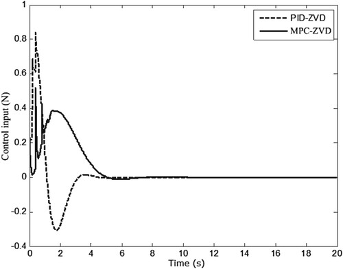
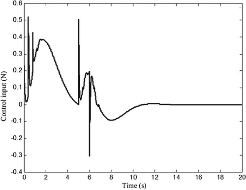
. The above MPC-ZVD algorithm is applied to the crane system, and results are shown in Figures . As can be seen from Figure , the trolley runs from the origin to the desired position without overshoot. Compared with the one of PID-ZVD control, its settling time is about 2 s longer. This is because the required control effort under MPC-ZVD is smaller than that under PID-ZVD, as shown in Figure . And the smaller control effort helps to reduce the swing range, as depicted in Figure . Concretely, the maximum value of offset zero is 0.034 rad under the control of PID-ZVD, while the maximum value of offset zero is 0.012 rad under the control of MPC-ZVD. In addition, all the constraints are satisfied. In summary, the MPC-ZVD control algorithm has certain advantages in reducing the swing angle.
Figure 9. Position response under the MPC-ZVD algorithm.
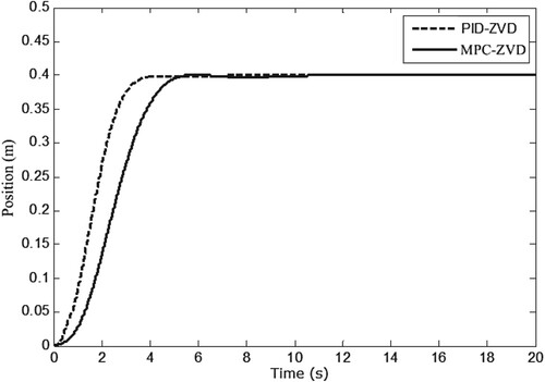
Figure 10. Swing response under the MPC-ZVD algorithm.
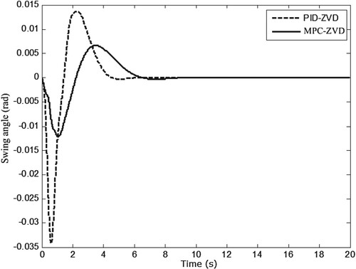
Figure 11. Control inputs under the MPC-ZVD algorithm.
In order to further highlight the advantages of the proposed control strategy, it is compared with the guaranteed MPC algorithm in the work (Chen et al., Citation2016). To this end, the friction force in (2) is set to zero to ensure the consistency of the plant, and the crane system parameters are changed to
kg,
kg,
m. Additionally, the constraints are
N and
, the desired position is
m.
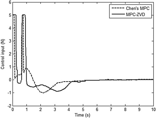
From the position response, these two MPC algorithms can make the trolley reach the desired position, and the control performance is almost the same, as shown in Figure . However, the swing response is different. Specifically, the maximum swing angle of the payload is smaller when the trolley is under the control of MPC-ZVD, as shown in Figure , which shows that the input shaper ZVD plays an active role in suppressing swing. Concretely, the maximum value of offset zero is 1.98° under the control of Chen’s MPC, while the maximum value of offset zero is 1.61° under the control of MPC-ZVD. The Figure describes the required control efforts, and they all reach the maximum limit. Nevertheless, the maximum lasts longer under the control of MPC-ZVD, the reason for this is the trolley reach the desired position faster. Through comparison, it can be seen that the MPC algorithms can effectively deal with constraint problems, and the MPC-ZVD algorithm can further reduce the swing angle of the payload.
Figure 12. Position response under the MPC algorithms.
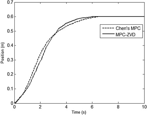
Figure 13. Swing response under the MPC algorithms.
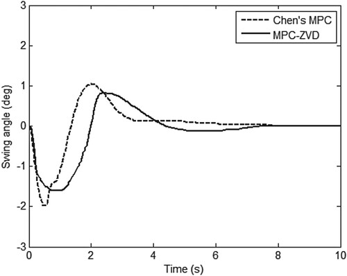
Figure 14. Control inputs under the MPC algorithms.
In order to test the robustness of the close-loop system, a wind disturbance is added to the system control channel at
s, and results are shown in Figures . Compared with the case without disturbance, as shown in Figure , the position response in the case of disturbance has a slight overshoot, as shown in Figure , but the overshoot can be eliminated quickly. This indicates that the closed-loop system has strong anti-disturbance ability, which is beneficial to ensure the control performance in practice. Figures and depict the swing angel and the control input, and they all vary within the allowable ranges.
Figure 15. Position response under the MPC-ZVD algorithm considering disturbance.
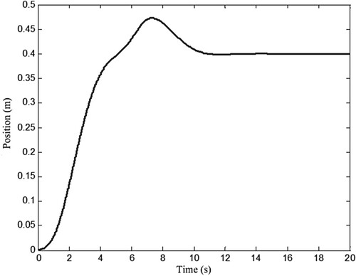
Figure 16. Swing response under the MPC-ZVD algorithm considering disturbance.
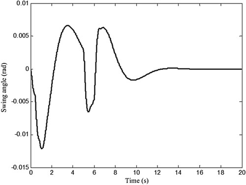
Figure 17. Control inputs under the MPC-ZVD algorithm considering disturbance.
5. Conclusions
A novel swing suppression scheme is presented for overhead cranes based on model predictive control combining with input shaping technology. It can be concluded from theoretical analysis and simulation results: (1) The ZVD shaper is a good open-loop control technique for overhead cranes, combined with a closed-loop control PID algorithm to help reduce the swing of payloads; (2) The constraint treatment is more intuitive, and compared with the conventional model predictive control and the PID–ZVD control algorithms, the proposed algorithm is more obvious to suppress the swing of payloads and (3) The proposed closed-loop system has a certain robustness to uncertainty. The next work will consider the control design in the presence of hoisting and heavy disturbances.
Disclosure statement
No potential conflict of interest was reported by the author(s).
Data availability statement
All data generated or analyzed during this study are included in this study.
Additional information
Funding
References
- Aguiar, C., Leite, D., Pereira, D., Andonovski, G., & Škrjanc, I. (2021). Nonlinear modeling and robust LMI fuzzy control of overhead crane systems. Journal of the Franklin Institute, 358(2), 1376–1402. https://doi.org/10.1016/j.jfranklin.2020.12.003
- Alghanim, K., Mohammed, A., & Andani, M. T. (2019). An input shaping control scheme with application on overhead cranes. International Journal of Nonlinear Sciences and Numerical Simulation, 20(5), 561–573. https://doi.org/10.1515/ijnsns-2018-0152
- Baumgart, M. D., & Pao, L. Y. (2007). Discrete time-optimal command shaping. Automatica, 43(8), 1403–1409. https://doi.org/10.1016/j.automatica.2007.01.003
- Chen, H., Fang, Y., & Sun, N. (2016). A swing constraint guaranteed MPC algorithm for underactuated overhead cranes. IEEE/ASME Transactions on Mechatronics, 21(5), 2543–2555. https://doi.org/10.1109/TMECH.2016.2558202
- Cuong, H. M., Dong, H. Q., & Van Trieu, P. (2021). Adaptive fractional-order terminal sliding mode control of rubber-tired gantry cranes with uncertainties and unknown disturbances. Mechanical Systems and Signal Processing, 154, 107601. https://doi.org/10.1016/j.ymssp.2020.107601
- Du, Y., Wang, C., Lu, J., & Zhou, Y. (2019). Vibration suppression using multi-impulse robust shaping method of zero vibration and derivative. Journal of Sound and Vibration, 440, 277–290. https://doi.org/10.1016/j.jsv.2018.10.038
- Elmorshedy, M. F., Xu, W., El-Sousy, F. F. M., Islam, M. R., & Ahmed, A. A. (2021). Recent achievements in model predictive control techniques for industrial motor: A comprehensive state-of-the-art. IEEE Access, 9, 58170–58191. https://doi.org/10.1109/ACCESS.2021.3073020
- Esleman, E. A., Önal, G., & Kalyoncu, M. (2021). Optimal PID and fuzzy logic based position controller design of an overhead crane using the Bees Algorithm. SN Applied Sciences, 3(10), 811. https://doi.org/10.1007/s42452-021-04793-0
- Gao, H., Zhang, J., & Tang, W. (2018). Offset-free trajectory tracking control for hypersonic vehicle under external disturbance and parametric uncertainty. Journal of the Franklin Institute, 355(3), 997–1017. https://doi.org/10.1016/j.jfranklin.2017.12.007
- Giacomelli, M., Faroni, M., Gorni, D., Marini, A., Simoni, L., & Visioli, A. (2018). Model predictive control for operator-in-the-loop overhead cranes. IEEE 23rd International Conference on Emerging Technologies and Factory Automation (ETFA), 1, 589–596. https://doi.org/10.1109/ETFA.2018.8502591
- Gu, X., & Xu, W. (2022). Moving sliding mode controller for overhead cranes suffering from matched and unmatched disturbances. Transactions of the Institute of Measurement and Control, 44(1), 60–75. https://doi.org/10.1177/0142331220922109
- Hewing, L., & Zeilinger, M. N. (2019). Scenario-based probabilistic reachable sets for recursively feasible stochastic model predictive control. IEEE Control Systems Letters, 4(2), 450–455. https://doi.org/10.1109/LCSYS.2019.2949194
- Hu, J., Shan, Y., Guerrero, J. M., Ioinovici, A., Chan, K. W., & Rodriguez, J. (2021). Model predictive control of microgrids–An overview. Renewable and Sustainable Energy Reviews, 136, 110422. https://doi.org/10.1016/j.rser.2020.110422
- Huang, J., Wang, W., & Zhou, J. (2021). Adaptive control design for underactuated cranes with guaranteed transient performance: Theoretical design and experimental verification. IEEE Transactions on Industrial Electronics, 69(3), 2822–2832. https://doi.org/10.1109/TIE.2021.3065835
- Huang, Y., Li, H., Zhou, J., & Meng, L. (2020). Extra-insensitive shaper with distributed delays: Design and vibration suppress analysis. Journal of Vibration and Control, 26(15-16), 1185–1196. https://doi.org/10.1177/1077546319894490
- Huseyin Bilgic, H., Conker, C., & Yavuz, H. (2021). Fuzzy logic–based decision support system for selection of optimum input shaping techniques in point-to-point motion systems. Proceedings of the Institution of Mechanical Engineers, Part I: Journal of Systems and Control Engineering, 235(6), 795–808. https://doi.org/10.1177/0959651820965705
- Jolevski, D., & Bego, O. (2015). Model predictive control of gantry/bridge crane with anti-sway algorithm. Journal of Mechanical Science and Technology, 29(2), 827–834. https://doi.org/10.1007/s12206-015-0144-8
- Kang, C. G., Hassan, R., & Kim, K. Y. (2020). Analysis of a generalized ZVD shaper using impulse vectors. International Journal of Control, Automation and Systems, 18(8), 2088–2094. https://doi.org/10.1007/s12555-019-0214-2
- Käpernick, B., & Graichen, K. (2013). Model predictive control of an overhead crane using constraint substitution. American Control Conference, 3973–3978. https://doi.org/10.1109/ACC.2013.6580447
- Khatamianfar, A., & Savkin, A. V. (2014). A new tracking control approach for 3D overhead crane systems using model predictive control. European Control Conference (ECC), 796–801. https://doi.org/10.1109/ECC.2014.6862298
- Lin, T., Ma, S., Ye, Y., & Zhang, S. (2021). An ADMM-based interior-point method for large-scale linear programming. Optimization Methods and Software, 36(2-3), 389–424. https://doi.org/10.1080/10556788.2020.1821200
- Maghsoudi, M. J., Ramli, L., Sudin, S., Mohamed, Z., Husain, A. R., & Wahid, H. (2019). Improved unity magnitude input shaping scheme for sway control of an underactuated 3D overhead crane with hoisting. Mechanical Systems and Signal Processing, 123, 466–482. https://doi.org/10.1016/j.ymssp.2018.12.056
- Mohamed, K. T., Abdel-Razak, M. H., Haraz, E. H., & Atef, A. A. (2022). Fine tuning of a PID controller with inlet derivative filter using Pareto solution for gantry crane systems. Alexandria Engineering Journal, 61(9), 6659–6673. https://doi.org/10.1016/j.aej.2021.12.017
- Mohammed, A., Alghanim, K., & Taheri Andani, M. (2020). An adjustable zero vibration input shaping control scheme for overhead crane systems. Shock and Vibration, 2020, 1–7. https://doi.org/10.1155/2020/7879839
- Ramli, L., Mohamed, Z., Abdullahi, A. M., Jaafar, H. I., & Lazim, I. M. (2017). Control strategies for crane systems: A comprehensive review. Mechanical Systems and Signal Processing, 95, 1–23. https://doi.org/10.1016/j.ymssp.2017.03.015
- Rodriguez, J., Garcia, C., Mora, A., Davari, S. A., Rodas, J., Valencia, D. F., Elmorshedy, M., Zuo, K., Tarisciotti, L., Xu, W., Zhang, Z., Zhang, Y., Norambuena, M., Emadi, A., Geyer, T., Kennel, R., Dragicevic, T., Khaburi, D. A., Zhang, Z., … Mijatovic, N. (2021). Latest advances of model predictive control in electrical drives—part II: Applications and benchmarking with classical control methods. IEEE Transactions on Power Electronics, 37(5), 5047–5061. https://doi.org/10.1109/TPEL.2021.3121589
- Schwenzer, M., Ay, M., Bergs, T., & Abel, D. (2021). Review on model predictive control: An engineering perspective. The International Journal of Advanced Manufacturing Technology, 117(5), 1327–1349. https://doi.org/10.1007/s00170-021-07682-3
- Shen, P. Y., Schatz, J., & Caverly, R. J. (2021). Passivity-based adaptive trajectory control of an underactuated 3-DOF overhead crane. Control Engineering Practice, 112, 104834. https://doi.org/10.1016/j.conengprac.2021.104834
- Shi, B., Peng, H., Wang, X., & Zhong, W. (2022). A symplectic direct method for motion-driven optimal control of mechanical systems. Communications in Nonlinear Science and Numerical Simulation, 111, 106501. https://doi.org/10.1016/j.cnsns.2022.106501
- Singer, N. C., & Seering, W. P. (1990). Preshaping command inputs to reduce system vibration. Journal of Dynamic System, Measurement, and Control, 112(1), 76–82. https://doi.org/10.1115/1.2894142
- Smoczek, J., & Szpytko, J. (2016). Particle swarm optimization-based multivariable generalized predictive control for an overhead crane. IEEE/ASME Transactions on Mechatronics, 22(1), 258–268. https://doi.org/10.1109/TMECH.2016.2598606
- Stomberg, G., Engelmann, A., & Faulwasser, T. (2021). A distributed active set method for model predictive control. IFAC-PapersOnLine, 54(3), 263–268. https://doi.org/10.1016/j.ifacol.2021.08.252
- Sun, Z., Ling, Y., Tan, X., Zhou, Y., & Sun, Z. (2021). Designing and application of type-2 fuzzy PID control for overhead crane systems. International Journal of Intelligent Robotics and Applications, 5(1), 10–22. https://doi.org/10.1007/s41315-020-00157-w
- Takahashi, H., Farrage, A., Terauchi, K., Sasai, S., Sakurai, H., Okubo, M., & Uchiyama, N. (2022). Sensor-less and time-optimal control for load-sway and boom-twist suppression using boom horizontal motion of large cranes. Automation in Construction, 134, 104086. https://doi.org/10.1016/j.autcon.2021.104086
- Tang, W., Long, W., & Gao, H. (2017). Model predictive control of hypersonic vehicles accommodating constraints. IET Control Theory & Applications, 11(15), 2599–2606. https://doi.org/10.1049/iet-cta.2017.0265
- Van den Broeck, L., Diehl, M., & Swevers, J. (2011). A model predictive control approach for time optimal point-to-point motion control. Mechatronics, 21(7), 1203–1212. https://doi.org/10.1016/j.mechatronics.2011.07.008
- Wei, Y., Li, B., Ou, P., & Zhang Q.-Z. (2019). Hybrid input shaping control scheme for reducing vibration of robot based on multi-mode control. Journal of Central South University, 26(6), 1649–1660. https://doi.org/10.1007/s11771-019-4119-2
- Wu, J., Guo, Z., & Song, B. (2009). Application of Lagrange equations in heat conduction. Tsinghua Ence & Technology, 14(S2), 12–16. https://doi.org/10.1016/S1007-0214(10)70023-7
- Wu, X., Xu, K., & He, X. (2020). Disturbance-observer-based nonlinear control for overhead cranes subject to uncertain disturbances. Mechanical Systems and Signal Processing, 139, 106631. https://doi.org/10.1016/j.ymssp.2020.106631
- Wu, Z., Xia, X., & Zhu, B. (2015). Model predictive control for improving operational efficiency of overhead cranes. Nonlinear Dynamics, 79(4), 2639–2657. https://doi.org/10.1007/s11071-014-1837-8