
 ?Mathematical formulae have been encoded as MathML and are displayed in this HTML version using MathJax in order to improve their display. Uncheck the box to turn MathJax off. This feature requires Javascript. Click on a formula to zoom.
Abstract
The application of modular multilevel converters (MMCs) to large drive systems is subject to severe low-frequency operation restrictions. The fluctuation of capacitor voltage and the high amplitude of common mode voltage in sub-modules is a thorny problem. In this paper, a novel fly-across capacitor modular multilevel converter topology is adopted to eliminate low-frequency voltage ripples by using the fly-across capacitor as a power transfer channel between the upper and lower bridge arms of the MMC. A novel finite compensation method is proposed—instead of the traditional full compensation method—that introduces a real-time variable limiting factor to change the amplitude of the mixed injected high-frequency differential-mode voltage and high-frequency differential-mode current and reduce the amplitude of the common-mode voltage on the AC side while lowering the current stress of the power devices. Finally, a complete system simulation model is constructed, and the topology with the proposed control strategy are verified to have good output characteristics under different operating conditions; good results are achieved in suppressing the sub-module fluctuation and common-mode voltage.
1. Introduction
Compared to the traditional two-level and three-level converters, the modular multilevel converter (MMC) is a promising alternative for medium- and high-voltage motor drive systems. This is due to its unique structural features, including a lower switching frequency, the generation of an approximate sinusoidal output voltage, and easy scalability; there is also no need for multi-winding phase-shifted transformer topology (Hassan et al., Citation2023; Liu et al., Citation2022; Zhou et al., Citation2023). In the petroleum, mining, traction, and steel industries, variable frequency drive systems are required to handle operating conditions at very low speeds or high-output torques.
The research on medium voltage for MMCs faces several specific challenges, including a capacitor voltage balance strategy, the suppression of common-mode voltage (CMV), and operation at low frequencies (Xu et al., Citation2017; Xu et al., Citation2023). As MMCs disperse and store the energy of the frequency converter in the capacitor of each sub-module (SM), the capacitor voltage fluctuation in the MMC operation state cannot be avoided when the capacitor of the SM is limited. A balanced control strategy based on a sequencing algorithm has been proposed in studies on capacitor voltage balance strategies for MMC SMs (Yue et al., Citation2023; Zhang et al., Citation2020a), but problems such as the large amount of calculation required by the algorithm, the large switching randomness of the SM, and the large power loss have not been solved. An SM capacitor voltage self-balancing control strategy based on a clamped self-voltage equalizing topology structure has been proposed (Zhang et al., Citation2020b). This method is simple in terms of control, has a good voltage equalizing effect, and reduces the amount of calculation in the control process. However, there are no in-depth and clear studies on the specific values of the circuit parameters and rotation control cycle. The voltage balance control strategy, which relies on the modulation of SM capacitors, successfully achieved both energy balance among the three-phase bridge arms and voltage balance across SM capacitors. However, the introduction of additional control links increased the system's complexity and impacted its stability (Behrouzian et al., Citation2017; Liu & Peng, Citation2020).
CMV has a large amplitude and dv/dt, which will produce overvoltage and bearing current due to the action of stray capacitance in the motor, then causing insulation breakdown of the motor winding and corrosion damage to the motor bearing, affecting the reliability and service life of the motor. A common mode LRC filter, a common mode choke, a common mode transformer, and other equipment can be added to suppress the source of the CMV flow, but these methods increase the hardware cost and volume, and the common mode filter design is complex (Jayaraman & Kumar, Citation2020; Jung et al., Citation2021; Zhang et al., Citation2021). It was found that various software control methods with improved PWM modulation strategies can greatly improve the economic efficiency of a CMV suppression scheme without reducing the power density of the system (Jiang et al., Citation2020;Wang et al., Citation2017).
Several studies have focused on methods to suppress low-frequency ripple in the capacitor voltage of MMC SMs, which can limit voltage fluctuation within a certain range by adding various forms of high-frequency (HF) CMV and HF circulation waveforms; however, there is still a problem with the large amplitude of output CMV at the AC side (Chen et al., Citation2022; Le & Lee, Citation2021; Zhou et al., Citation2021). Based on an optimal selection method for the average voltage of SM capacitors (Kumar & Poddar, Citation2018), this method allows for the high voltage ripple on SM capacitors to fluctuate within the voltage limit of the capacitor without injecting HF CMV and HF circulation; however, this method is applied to medium and HF operations, and has difficulty meeting low-frequency operation conditions. A finite compensation method was developed to replace the traditional full compensation method in order to reduce the amplitude of the injected HF current, and achieved good results (Guan et al., Citation2019). An improved SM topology suppressed the voltage ripple generated by the SM in low-frequency operation by using the active power decoupling method, but the improved SM increases the huge cost investment, the decoupling process was too complicated, and the realization cost and difficulties encountered during the actual project were relatively high (Nguyen et al., Citation2023). Another study presented an enhanced MMC topology featuring self-balancing mechanisms, ensuring balanced capacitor voltage operation with reduced ripple, higher current distortion rates, and the minimization of output torque effects, especially under zero/low-frequency conditions (Elserougi et al., Citation2021). The structure of a flyover capacitor modular multilevel converter was adopted, and the traditional double-HF sine wave of control injection was adopted to cause large bridge arm circulation, which was applied to the motor winding; this resulted in winding insulation deterioration and motor bearing damage (Du et al., Citation2017; Le & Lee, Citation2022). In order to address the CMV and SM voltage fluctuation issues during motor startup, researchers employed a fly-across-capacitor modular multilevel converter (FC-MMC). In this case, the motor was simulated with inductive load, and the various working conditions and motor operating characteristics in the actual operation process of the motor were not considered (Wang et al., Citation2021).
To solve the problem of the low-frequency ripple of CMV and SM capacitor voltage mentioned above, the present paper introduces a limit factor that can be changed in real-time according to the output speed of the motor, and combines the mixed injection method that controls the HF difference mode square wave voltage with HF sine circulation to realize the safe operation of the motor in the full speed domain. In addition, considering the dynamic frequency conversion characteristics of the drilling rig during operation, the special structure of the repetitive controller is adopted to eliminate multiple harmonic components and further suppress the fluctuation of the capacitor voltage of the SM. Finally, a simulation analysis of the FC-MMC-driven permanent magnet synchronous motor under different working conditions is carried out, and the results show that the proposed control strategy can effectively suppress the capacitor voltage fluctuation of the SM and that the motor has a good output performance.
2. FC-MMC topology and operating principle
2.1. FC-MMC topology
The topology structure of the FC-MMC inverter is shown in Figure . Similar to the traditional MMC, the FC-MMC also consists of three-phase bridge arms. However, it includes a flying capacitor CF, connected between the midpoint of the upper bridge arm and the midpoint of the lower bridge arm, which further divides the upper and lower bridge arms into four half-bridge arms. Each half-bridge arm is composed of several SM units and a current-limiting inductor L. However, the traditional MMC and FC-MMC topologies have similar structural characteristics, and the operating mechanism is the same as that of the control target. To achieve similar effects, the total inductance of the bridge arms in the proposed configuration remains the same as the total inductance of the bridge arms in the traditional MMC.
Figure 1. Topology of the FC-MMC converter.
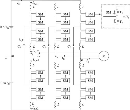
In the diagram, Udc represents the DC-side voltage of the FC-MMC; Idc represents the DC-side output current; ia,p1, ia,p2, ia,n1, ia,n2 correspond to the current in the upper and lower half-bridge arms of phase A; ia,F represents the current flowing through the flying capacitor of phase A; p indicates the upper bridge arm, n indicates the lower bridge arm; and ix represents the phase current of the AC-side output (x = a,b,c).
2.2. FC-MMC operating principle
To provide a more simplified analysis of the operating principles of FC-MMC, Figure presents the single-phase equivalent circuit of the FC-MMC. The four half-bridge arm voltages are ux,p1, ux,p2, ux,n1, and ux,n2, and each half-bridge arm consists of three main parts: base frequency voltage 0.5ux, DC voltage 0.25Udc, and HF differential-mode voltage ux,h.
Figure 2. FC-MMC simplified single-phase equivalent circuit diagram.
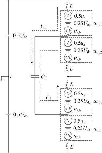
By controlling the total number of SMs in each phase leg to be N, a DC voltage is generated to support the DC bus voltage; the reverse-directional fundamental voltage components in the upper and lower phase legs are used to support the persistence of the output voltage on the motor side; and an HF differential-mode voltage with the same amplitude and opposite phase is injected into each phase half-bridge to maintain a constant total voltage across the bridge arms. With the assistance of the flying capacitor, an internal power transmission loop is formed. Moreover, due to the opposite phases of the injected HF components, their effects on both the DC side and the motor side will mutually cancel out, thus not affecting the output CMV.
3. SM voltage fluctuation suppression principle
When the FC-MMC drives the motor in a stuck-drill situation, it operates at an extremely low speed. In this situation, the FC-MMC needs to provide low-frequency current to the motor, and the interaction between the low-frequency current and the DC voltage component leads to significant fluctuations in bridge arm power. As the motor speed decreases, the amplitude of the output voltage also decreases. Not injecting HF components would cause significant fluctuations in bridge arm voltages. Moreover, the low-frequency current flowing through the SMs would result in substantial power fluctuations, leading to increased fluctuations in the capacitor voltages. It can be seen from Figure that, to suppress the fluctuation of the SM capacitor voltages in addition to the fundamental voltage and the DC voltage, HF components need to be injected into each bridge arm.
The voltage drop of the inductance of the bridge arm in the flyover modular multilevel is usually caused by the transient voltage change, which is produced by the switching action of the switching device when the frequency converter is operating. The voltage drop caused by these changes in the inductance is often transient and of small magnitude. Therefore, regardless of the resistance sensing the voltage drop of the bridge arm in Figure , the voltages of the upper and lower bridge arms are, respectively, expressed as:
(1)
(1)
At this point, it is assumed that the output phase voltage ux per phase and the HF differential-mode voltage ux,h can be expressed as follows, respectively:
(2)
(2)
(3)
(3) In Equations (2)(3): Uo indicates the amplitude of the output phase voltage; Uh indicates the amplitude of the injected HF differential-mode voltage; f indicates the frequency of the fundamental frequency component; fh indicates the frequency of the HF component; and
indicates the initial phase angle of each phase bridge arm.
Based on the defined direction of bridge arm currents in Figure and Figure , the relationship between different currents in the A phase bridge arm can be expressed as follows:
(4)
(4) In Equation (4): ix,d denotes the DC bus current; ix denotes the AC output current; and ix,h denotes the injected differential mode HF current.
At this point ix and ix,h are expressed as:
(5)
(5)
(6)
(6)
In Equations (5)(6): Io denotes the AC output current amplitude; Ix,h denotes the injected differential mode HF current amplitude; and denotes the phase angle between the output voltage and the output current.
By neglecting minor HF power components, the instantaneous power of each phase's half-bridge arm in the FC-MMC can be obtained by multiplying Equation (1) with Equation (4) as:
(7)
(7)
From Expression (7), it can be seen that the power of the four half-bridge arms is composed of five relational expressions, and the symbols of the first term and the second term in each half-bridge arm expression are the same after longitudinal comparison. This has little impact on the total power of the whole phase, so the low-frequency circulation component for the AC/DC transmission power can be obtained. The third and fourth terms of the two half-bridge arms of the upper bridge arm are ‘+’ and ‘−’, respectively. The third and fourth terms of the two half-bridge arms of the lower bridge arm are opposite in polarity, resulting in the power difference between the upper and lower bridge arms. This power difference can be offset by the last HF difference mode voltage ux,h and HF current ix,h. The power balance expression can then be obtained as:
(8)
(8)
In Equation (8),
Then, the DC current ix,d and the HF current Ix,h amplitude are:
(9)
(9) To better suppress the low-frequency voltage ripple of the SM and reduce the magnitude of the bridge arm CM current, it is desirable to maximize the value of Uh within the allowed range. The range of Uh can be obtained from Equation (1) as follows:
(10)
(10)
Assuming that the system modulation system is m, the maximum value of the injected differential-mode HF voltage amplitude can be found by combining Equation (10):
(11)
(11)
To improve the utilization efficiency of the HF differential-mode voltage, we change its injection form to a square wave, at which point there are:
(12)
(12)
Due to the special topology of the FC-MMC converter, its half-bridge arms all have inductance L. The injected HF square wave current is not easy to control, so HF sinusoidal current injection is still used.
Taking into account the dynamic frequency conversion characteristics during a drilling rig operation, the output of the FC-MMC converter must meet the requirements of different working conditions. When the motor speed is higher than a specific speed, the power imbalance in the bridge arms is small. If the FC-MMC converter continues to introduce HF components into the system, it will have a negative impact on the safe operation of the FC-MMC converter and increase the losses in the power equipment. Therefore, the HF current can be removed when the motor reaches a certain speed. This function can be achieved by introducing a frequency limiting factor KFC, with the following functional expressions:
(13)
(13)
4. Low-frequency operation control method
The rotary motor of the oil drilling rig can adapt to different operating conditions, and comprehensive balance control must be applied to the overall system. Comprehensive balance control consists of five main parts: permanent magnet synchronous motor vector control, inter-phase capacitor voltage control, upper and lower bridge arm capacitor voltage control, half-bridge arm capacitor voltage control, and independent control of individual SMs’ capacitor voltage. The low-frequency control principles are illustrated in Figure .
Permanent magnet synchronous motor control
Figure 3. Low-frequency control block diagram of the FC-MMC: (a) Permanent magnet synchronous motor control ; (b) inter-phase capacitive-voltage control; (c) capacitive-voltage control between upper and lower bridge arms; (d) half-bridge arm capacitor voltage control; (e) independent control of the capacitance voltage of the SMs.
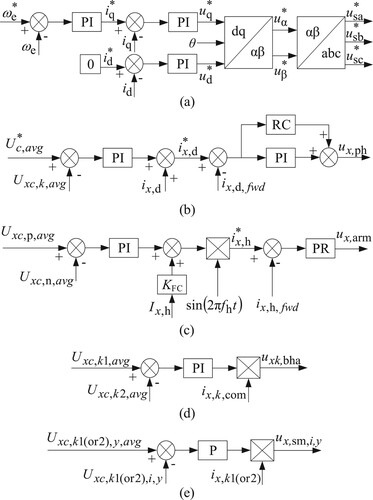
Figure (a) illustrates the vector control employed for the permanent magnet synchronous motor (PMSM). The actual speed
of the turntable motor is obtained by the sensor, and the reference value
is obtained by the speed PI controller from the difference between the rated speed
and the actual speed
. Then, the reference value
is obtained by the current PI controller from the difference between
and the actual value
. The difference between the reference value
and the actual value
is then passed through the current PI controller to obtain
. The final turntable motor modulation signal
is obtained after the coordinate change.
Inter-phase capacitance voltage control
Figure (b) illustrates the control of the interphase capacitance voltage. When the turntable motor speed changes, does its output current frequency. A proportional resonant (PR) controller can only track sinusoidal signals of specific frequencies without a static difference; when there are harmonics of multiple frequencies, multiple PR controllers need to be connected in parallel. The use of repetitive controllers can not only make up for the former deficiency but can also accurately track periodic signals and their multiplicative harmonics. By subtracting the average voltage of the interphase capacitance from the set value of the SM capacitance voltage (k = p,n) and then passing it through a PI controller, the DC circulating current value of the bridge arm is obtained. The DC circulating current value is added to ix,d to obtain the DC and the two-fold circulating current command value; then, it is differenced with ix,d,fwd, and then the PI control and the RC phase are connected in parallel to track and control the circulating current command value to obtain the final inter-phase capacitor voltage correction ux,ph.
(14)
(14) In Equation (14): uxc,k1,i represents the SM capacitance voltage within the front half-bridge arm of each phase, uxc,k2,i represents the SM capacitance voltage within the rear half-bridge arm of each phase, ix,d represents the feedforward value of the bridge arm circulating current for each phase, and ix,d,fwd represents the feedback value of the interphase capacitance voltage control circulating current for each phase.
Capacitor voltage control between upper and lower bridge arms
Figure (c) illustrates the interphase capacitance voltage control between the upper and lower bridge arms. Taking the difference between Uxc,p,avg and Uxc,n,avg and then passing it through a PI controller, the required amplitude of the HF current injection for balancing the power imbalance of the bridge arms is obtained. It is added to the feedforward value Ix,h and is multiplied by the HF sinusoidal current to form the HF current command value
. Taking the difference between
and ix,h,fwd and passing it through a PR controller, the final correction value of the inter-arm capacitance voltage between the bridge arms, denoted as ux,arm, is obtained.
(15)
(15) In Equation (15): Uxc,p,avg is the average value of the capacitance voltage of the upper bridge arm SM per phase; Uxc,n,avg is the average value of the capacitance voltage of the lower bridge arm SM per phase; and ix,h,fwd is the actual feedback value of the HF current.
Half-bridge arm capacitor voltage control
Figure (d) illustrates the control of the half-bridge arm capacitor voltage. From the difference between Uxc,k1,avg and Uxc,k2,avg, the half-bridge arm inter-SM capacitor charging and discharging current is obtained by the PI controller and is then multiplied with ix,k,com to obtain the half-bridge arm capacitor voltage correction uxk,bha.
(16)
(16)
In Equation (16): Uxc,k1,avg represents the average value of the capacitor voltage in the front half-bridge arm; Uxc,k2,avg represents the average value of the capacitor voltage in the rear half-bridge arm of the SM; and ix,k,com represents the CM component of the corresponding inter-SM current.
Independent control of capacitance voltage of SM
Figure (e) illustrates the independent control of the capacitor voltage for each SM unit. The average value of the capacitance voltage of each sub-bridge arm Uxc,k1(or2),y,avg(y = 1∼0.5N) and the actual value of the capacitance voltage of each individual SM Uxc,k1(or2),i,y of each phase are differenced and multiplied by the output of the proportional (P) controller and the corresponding half-bridge arm current ix,k1(or2) of the individual SM to obtain the final individual SM capacitance voltage. The correction quantity is ux,sm,i,y.
In summary, the reference voltage values for each SM are obtained as:
(17)
(17)
5. Validation analysis
This paper focuses on the FC-MMC type inverter driving a PMSM, and simulates the turntable motor in the oil drilling system using simulation software. The analysis includes the SM capacitor voltage fluctuations, speed control performance, and motor load characteristics under different complex operating conditions. The system’s simulation parameters are described in Table . Since the FC-MMC type inverter controls each phase independently, the following analysis and discussion will focus on phase A.
Normal system start-up conditions
Table 1. Simulation parameters of FC-MMC drive rotary motor.
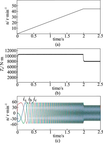
The set turntable motor speed with the FC-MMC type converter is 45r/min and the set load torque Te is 8000N·m at 2s. Figure depicts the simulation of the turntable motor system during a normal start-up process until the rated speed is reached. Figure (a) shows the turntable motor starting the rated speed curve, with no speed overshoot, reaching the rated speed of the turntable motor within 2s. This represents a good dynamic response, and the static difference rate remains within 1%. Figure (b) presents the Te curve of the electromagnetic torque of a turntable motor, showing that the starting acceleration is constant, the starting torque is large, and the torque fluctuation is small. Figure (c) shows the stator current ix curve of the turntable motor during the normal start-up of the system; the starting torque of the turntable motor leads to a large starting current, which remains stable within 0.15s.
Figure 4. Simulation results from start-up of the rotary motor to rated speed: (a) turntable motor speed; (b) turntable motor output torque; (c) turntable motor stator current.
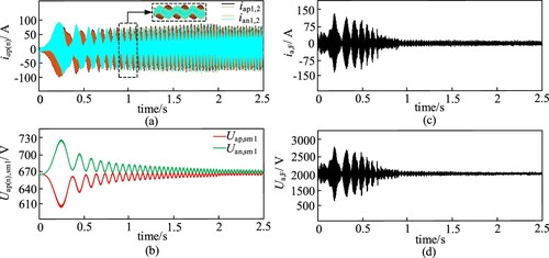
The simulation results of the FC-MMC’s normal start-up to rated speed are shown in Figure . Figure (a) displays the current waveforms of the per-phase half-bridge SMs in the FC-MMC during normal system start-up. During the start-up phase, the amplitudes of the two HF components are equal but in opposite directions. Figure (b) represents the waveform of the individual SMs’ capacitor voltage in the FC-MMC. The fluctuation of the SMs’ capacitor voltage during the startup of the rotary motor is suppressed to approximately 10%. Figure (c) shows the FC-MMC fly span SM capacitor current waveform. When the turntable motor output frequency is greater than the set HF value, the difference in power between the bridge arms is not large, and the injection of HF current is stopped at this time. Figure (d) shows the FC-MMC fly span SM capacitor voltage waveform. When the turntable motor is larger than the set HF value and the injection of HF differential-mode voltage is stopped, the fly span SM voltage keeps fluctuating above and below Udc/2 and does not flow to the motor side. Through the above analysis, we can see that, when the turntable motor proceeds from zero to rated speed, the safe start-up of the motor is ensured by using the limit injection method proposed in this paper, and the maximum voltage fluctuation of the SM is about 10%, which proves the correctness and feasibility of the adopted method.
Variable load and stuck drill operating conditions
Figure 5. Simulation results of FC-MMC start-up to rated speed: (a) FC-MMC upper and lower half-bridge arm current; (b) FC-MMC upper and lower bridge arm individual SM capacitance voltage; (c) FC-MMC fly span SM capacitor current waveform; (d) FC-MMC fly span SM capacitance voltage waveform.
During the extraction process of oil drilling systems, encountering problems such as shale expansion and wellbore collapse can lead to the blockage of drilling equipment. Figure represents the simulation of the turntable motor under varying loads and stuck drilling conditions. As can be seen from Figure (a), the speed response of the oil rig turntable motor shows no overshoot and is maintained close to the rated speed. Figure (b) shows that, at 3 s, the oil rig encounters shale expansion, causing a sudden increase in torque of around 25% for the turntable motor. From Figure (c), it can be seen that the sudden increase in torque causes a decrease in the rotational speed of the oil rig by approximately 0.05 r/min, and the stator current of the turntable motor increases.
Figure 6. Simulation results of the rotary motor under variable load and stuck drilling conditions: (a) turntable motor speed; (b) turntable motor output torque; (c) turntable motor stator current.
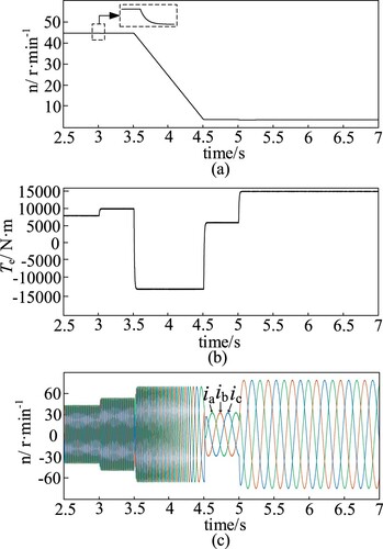
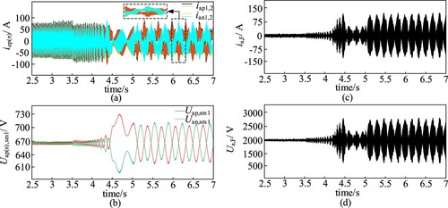
Figure represents the simulation of the FC-MMC under variable load and stuck drilling conditions. At 3.5s, the turntable motor speed is set to 6r/min and the torque load is 8000N·m. At this time, the turntable motor is braking and the torque is negative. At 4.5s, the turntable motor reaches the set speed of 6r/min; in order to solve the stuck drilling condition, the output torque Te increases to 15000N·m at 5s, and the turntable motor starts to run at low speed with large torque, which accelerates the energy exchange between SMs due to the HF injection method, as shown in Figure (a-d). This results in the increase of SM capacitance voltage fluctuation to about 6%. The above analysis shows that the maximum value of the fluctuation of SM capacitance voltage is about 11% when the turntable motor is operated under variable load and jamming conditions, which indicates that the turntable motor with the FC-MMC type converter has good immunity and strong robustness.
Reversing operating conditions
Figure 7. Simulation results of FC-MMC under variable load and stuck drilling conditions: (a) FC-MMC upper and lower half-bridge arm current; (b) FC-MMC upper and lower bridge arm individual SM capacitance voltage; (c) FC-MMC fly span SM capacitor current waveform; (d) FC-MMC fly span SM capacitance voltage waveform.
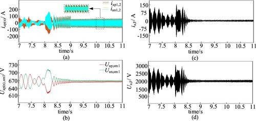
Oil drilling will face complex changes in the working environment, and the reversal of the turntable motor is therefore an important indicator for testing the dynamic performance of the system. Figure shows the simulation results of the turntable motor reversal condition. At 7.5s, the turntable motor jamming condition is solved and the turntable motor torque Te drops to 8000N·m. Figure (a-c) shows that, at 9s, the motor reaches the reverse-rated speed without overshoot, exhibits minimal torque fluctuations, and has low distortion in the three-phase sinusoidal currents.
Figure 8. Simulation results of rotary motor inversion condition: (a) turntable motor speed; (b) turntable motor output torque; (c) turntable motor stator current.
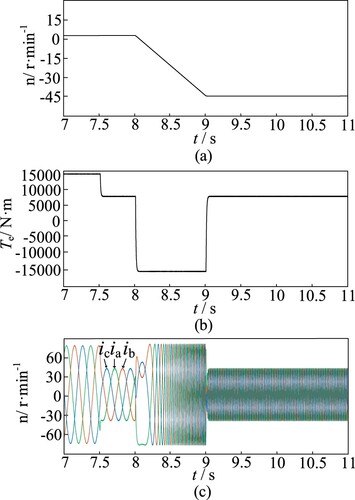
Figure (a-d) shows that, during the motor reversal process, the injected HF components are increased to compensate for the power imbalance in the bridge arms, and the FC-MMC fly across the SM capacitance voltage fluctuates greatly when the turntable motor reverses to reach the set rated speed, and gradually tends to a stable state. In Figure (b), due to the adoption of the combined action of injecting HF components to counteract the low-frequency ripple components in the SM capacitor voltage, caused by the suppression of hybrid HF pulsation, the voltage drop across the bridge arm inductance will increase. As a result, the SM capacitor voltage will unavoidably deviate from the rated voltage value of 666 V and exhibit a stable point at a different value. Therefore, the forward and reverse rotation experiment of the turntable motor proves the bi-directional energy flow function and the four-quadrant operation of the FC-MMC type converter.
Comparative analysis
Figure 9. Simulation results of FC-MMC inversion condition: (a) FC-MMC upper and lower half-bridge arm current; (b) FC-MMC upper and lower bridge arm individual SM capacitance voltage; (c) FC-MMC fly span SM capacitor current waveform; (d) FC-MMC fly span SM capacitance voltage waveform.
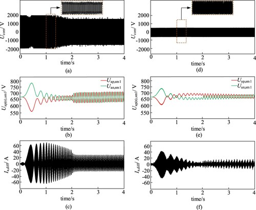
Set the turntable motor regulation system to m = 1/3 and the motor speed from 0 to 15r/min, so that the turntable motor is in the output medium frequency 10 Hz stage. Figure (b) and Figure (e) show a comparison between the traditional MMC and the FC-MMC; due to the oil drilling turntable motor start-up phase, the motor speed is almost zero, and when using the FC-MMC SM capacitor voltage fluctuation rather than the traditional MMC, it decreased by about 8%. From Figure (a) and Figure (d), we can see that the HF CMV injected by the traditional MMC has a larger amplitude, which causes the output CMV of the motor side to be almost equal to the injected CMV amplitude. In contrast, using the FC-MMC topology to inject HF differential-mode voltage, the output CMV amplitude of the drilling rig turntable motor is lower throughout the mid-frequency operating range, with an amplitude of about Uc. Meanwhile, due to the special channel of the topology presented in this paper, these results are compared with the conventional MMC and are shown in Figure (c) and Figure (f). The figures show that the circulating current amplitude of the bridge arm is reduced by about 40%, which relieves the bridge arm’s current stress. The points of excellence of, and the problems that can be solved with, the FC-MMC topology compared to the conventional topology are further illustrated.
Figure 10. Simulation results comparing MMC with FC-MMC: (a) MMC motor side CMV waveform; (b) MMC upper and lower bridge arm individual SM capacitance voltages; (c) MMC bridge arm circulation; (d) FC-MMC AC side CMV waveform; (e) FC-MMC upper and lower bridge arm individual SM capacitance voltages; (f) FC-MMC bridge arm circulation.
6. Conclusion
Aiming to solve the problems of CMV and HF circulating current in the traditional MMC converters for rotary table motors, a new FC-MMC topology is adopted and a new semi-compensated low-frequency control strategy is researched to satisfy different operating conditions and achieve the reliable operation of the rotary table motor in the full-frequency domain. The results show that, in comparison with the conventional topology, using the new FC-MMC topology and the proposed low-frequency control strategy can reduce the output CMV of the AC side of the FC-MMC in the motor start-up phase to about one third of that of the conventional MMC. The amplitude of the voltage fluctuation of the SM capacitor is reduced by about 9% and the circulating current of the bridge arm is reduced by 40%. Additionally, the torque ripple of the turntable motor is small, there is no overshoot in the rotational speed, and the output current is highly sinusoidal, demonstrating that the proposed control strategy ensures the reliability of the overall turntable motor system under different operating conditions.
Disclosure statement
No potential conflict of interest was reported by the author(s).
Additional information
Funding
References
- Behrouzian, E., Bongiorno, M., & Teodorescu, R. (2017). Impact of switching harmonics on capacitor cells balancing in phase-shifted PWM-based cascaded H-bridge statcom. IEEE Transactions on Power Electronics, 32(1), 815–824. https://doi.org/10.1109/TPEL.2016.2535481
- Chen, Q., Xie, R., Lu, H., Zheng, X., Hang, L. J., Fu, C. X., He, Z., He, Y. B., Zeng, P. L., & Qiu, J. (2022). Hybrid injection strategy of sub-module voltage ripple suppression for MMC under low frequency operation. Energy Reports, 8, 1454–1465.
- Du, S. X., Wu, B., Zargari, N. R., & Cheng, Z. Y. (2017). A flying-capacitor modular multilevel converter for medium-voltage motor drive. IIEEE Transactions on Power Electronics, 32(3), 2081–2089.
- Elserougi, A. A., Abdelsalam, I., Massoud, A., & Ahmed, S. (2021). Modular multilevel converter with self-energy equalization for medium voltage AC drive applications. IEEE Transactions on Industry Electronics, 68(12), 11881–11894.
- Guan, W. D., Huang, S. D., & Huang, X. Q. (2019). Modified MMC and its capacitor voltage ripple suppression method employed in medium-voltage wind generator system. IET Power Electronics, 12(12), 3185–3196.
- Hassan, Z., Watson, A. J., Tardelli, F., & Clare, J. (2023). A Switched mid-point modular multilevel converter for HVDC applications. IEEE Transactions on Power Delivery, 38(3), 1534–1547. https://doi.org/10.1109/TPWRD.2022.3217715
- Jayaraman, K., & Kumar, M. (2020). Design of passive common-mode attenuation methods for inverter-fed induction motor drive with reduced common-mode voltage PWM technique. IEEE Transactions on Power Electronics, 35(3), 2861–2870. https://doi.org/10.1109/TPEL.2019.2930825
- Jiang, W. D., Wang, P. D., Ma, M. N., Wang, J. P., Li, J. S., Li, L. B., & Chen, K. W. (2020). A novel virtual space vector modulation with reduced common-mode voltage and eliminated neutral point voltage oscillation for neutral point clamped three-level inverter. IEEE Transactions on Industry Electronics, 67, 884–894.
- Jung, J., Hwang, S. & Kim, J. (2021). A common-mode voltage reduction method using an active power filter for a three-phase three-level NPC PWM converter. IEEE Transactions on Industry Applications, 57(4), 3787-3800.
- Kumar, Y. S., & Poddar, G. (2018). Medium-voltage vector control induction motor drive at zero frequency using modular multilevel converter. IEEE Transactions on Industry Electronics, 65(1), 125–132.
- Le, D. D., & Lee, D. (2021, June 28). A modified modular multilevel converter with features of reduction of submodule capacitor fluctuation and fault-tolerant operation. 2021 IEEE 12th International Symposium on Power Electronics for Distributed Generation Systems (PEDG).
- Le, D. D., & Lee, D. (2022). A modular multilevel converter topology with novel middle submodules to reduce capacitor voltage fluctuations. IEEE Transactions on Power Electronics, 37(1), 70–75.
- Liu, Y. J., Hu, H. T., Yang, X. W., Hu, H. H., He, Z. Y., & Zhu, X. J. (2022). Distributed coordinated control strategy for flexible medium voltage direct current railway traction power system. Electric Power Automation Equipment, 42(12), 184–190.
- Liu, Y. T., & Peng, F. Z. (2020). A modular multilevel converter with self-voltage balancing part I: mathematical proof. IEEE Journal of Emerging and Selected Topics in Power Electronics, 8, 1117–1125.
- Nguyen, V., Kim, J., Park, J., Lee, J., & Park, B. (2023). A modified submodule of modular multilevel converter using active power decoupling method for reducing capacitor voltage ripple under low-frequency operation. IET Power Electronics, 16(5), 868–882.
- Wang, F. S., Weng, S., Zhang, X., & Chen, T. (2021). A low-frequency control strategy of flying-capacitor MMC. Power Electronics, 55(11), 120–124.
- Wang, J. P., Gao, Y., & Jiang, W. D. (2017). A carrier-based implementation of virtual space vector modulation for neutral-point-clamped three-level inverter. IEEE Transactions on Industry Electronics, 64(12), 9580–9586.
- Xu, D. G., Li, B. B., & Zhou, S. Z. (2017). Overview of the modular multilevel converter based high voltage motor drive. Transaction of China Electrotechnical Society, 32(20), 104–116.
- Xu, X. N., Wang, K., Zheng, Z. D., & Li, Y. D. (2023). A review on common-mode voltage reduction methods for three-phase PWM converters. Proceedings of the CSEE, 1–19.
- Yue, Y. J., Fan, Y. Z., Zhao, H., & Wang, H. J. (2023). Research on the capacitor voltage balancing control strategy of MMC sub-module based on improved sorting algorithm. Electrical Measurement & Instrumentation, 60(8), 81–84.
- Zhang, J., Zeng, G. H., Zhao, J. B., Huang, B., & Xiao, B. (2020a). Modular multilevel converter capacitor voltage balancing strategy based on improved bubble sorting. Power System Protection and Control, 48(6), 92–99.
- Zhang, J. P., Cui, D. Q., Tian, X. C., & Zhao, C. Y. (2020b). Self-block and voltage balance modular multilevel converter sub module topology and control. Transactions of China Electrotechnical Society, 35(18), 3917–3926.
- Zhang, Y. C., Shen, Z. W., & Jiang, D. (2021). An integrated EMI filter scheme for paralleled inverter with zero-cm PWM algorithm. IEEE Journal of Emerging and Selected Topics in Power Electronics, 9(1), 716–726.
- Zhou, S. Z., Li, B. B., Wang, J. K., & Xu, D. G. (2021). A modified modular multilevel converter for motor drives capable of high-torque operation at zero/low motor speeds. IEEE Transactions on Circuits and Systems II-Express Briefs, 68(7), 2493–2497.
- Zhou, Y. Y., Qin, L., Yang, S. Q., Yu, X., Pu, Q. X., Liu, Z. X., & Liu, K. P. (2023). Research progress of capacitor voltage balancing strategies for modular multilevel converters. Power System Technology, 47(1), 322–337.