ABSTRACT
Touch is produced by sensations that include approaching, sliding, pressing, and temperature. This concept has become a target of research in biotechnology, especially in the field of bionic biology. This study measured sliding and pressing with traditional tactile sensors in order to improve a machine operator's judgment of surface roughness. Based on the theory of acoustic emission, this study combined polyvinylidene fluoride (PVDF) with a sonic transducer to produce tactile sensors that can detect surface roughness. Friction between PVDF films and experimental materials generated tiny acoustic signals that were transferred into electrical signals through a sonic transducer. The characteristics of the acoustic signals for the various materials were then analyzed. The results suggest that this device can effectively distinguish among different objects based on roughness. Tactile sensors designed using this principle and structure function very similarly to the human body in recognizing the surface of an object.
Introduction
Tactile sensors represent a key technology in the development of intelligent robots.Citation1 Therefore, biotechnology researchers are investing effort in designing robots with the same perception capacity as humans. Tactile sensors are regarded as an indispensable medium to connect robots with the real environment, and they are widely used to imitate human hands through the perceptive cognitions of touching, sliding, and heating. In recent years, in-depth research into dexterous robotic hands has yielded great success in replicating a reliable grab. Currently, polyvinylidene fluoride (PVDF) is widely accepted as an ideal material for tactile sensors because it has special properties that make it possible to gather information that cannot be obtained by the naked eye, including mechanical properties, thermal properties, and vibration properties.Citation2
Dargahi from Simon Fraser University analyzed the piezoelectric and pyroelectric properties of PVDF film, as well as its dynamic response.Citation3 The transient responses recorded in the experiments allowed them to distinguish between piezoelectric and pyroelectric incentives: The time durations of the transient response signals gradually lengthened as the incentive progressed from piezoelectric to piezoelectric-pyroelectric hybrid to a pure thermal response. Based on these results, tactile sensors consisting of 3 pieces of PVDF were put forward. Similarly, Chinese universities and companies have recently released tactile sensors based on PVDF. Researchers at Zhejiang Sci-Tech University developed a new multiple-finger touch system based on PVDF piezoelectric thin-film technology. This new invention has successfully improved the scraping precision of the operator.Citation4,5,6,7
These examples illustrate that most current studies of PVDF film are based on its piezoelectric and pyroelectric properties. Like human hands, the hands of an intelligent robot also need the ability to detect the temperature and pressure of unknown objects. However, 2 factors make it impossible for a robot to “feel” surface roughness: the high price and complexity of a vision system, and the obstacles that exist between vision sensors and objects. Therefore, the industry desperately needs a sensor that can distinguish between materials with different levels of roughness. This paper describes a PVDF film tactile sensor based on the principle of acoustic emission. The proposed sensor is small in volume and easy to use in detecting the surface roughness of objects. This paper also verifies the feasibility of PVDF film as a sensitive material for application in tactile sensors.
Acoustic emission testing
Friction is a ubiquitous and complicated dynamic process that is affected by a number of factors including adhesion, rough deformation, and pear ditch of hard rough.Citation8 Surface roughness is an important factor because the contact surface between objects always features unsmooth microstructures. Acoustic emission (AE) is a phenomenon in which a material emits a transient elastic wave due to a rapid energy release. The AE wave is produced by changes in stress distribution in the contact area when 2 objects rub against each other, and it has a random characteristic. It can be described by an AE signal and detected by an acoustic sensor. Previous work has demonstrated that the elasticity and plasticity of an object with a rough surface can dramatically change under pressure, leading to stronger stress waves. Therefore, the surface roughness of an object by detecting a characteristic value of the AE signal in real-time.
In order to simulate the human tactile sensor as closely as possible, this study applied PVDF membrane adhesive to the surface of the sensor, increasing the sensor's slipping degree. The results demonstrate that the PVDF membrane on the surface of the sensor not only allows the sensor to behave like a finger sliding along the surface of an object, but also improves the vibration signal of the output signal-to-noise ratio (SNR).
Experimental study
The signal acquisition device used in this experiment is composed primarily of PVDF film, an acoustic-electricity converter, and a fixture, as shown in .
Figure 1. Sensor device. The signal acquisition device is composed primarily of PVDF film, an acoustic-electricity converter, and a fixture composed primarily of PVDF film, an acoustic-electricity converter, and a fixture.
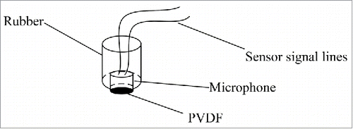
As the contact surface, the PVDF film adheres to a miniature microphone, which in turn is fixed to a piece of rubber. The sensor's signal wires lead from the rubber block into a data acquisition circuit.
When the contact surface of the sensor rubs against the surface of the tested object, an acoustic-electric converter gathers vibrations and converts them to an electrical signal.Citation9 This experiment used a small microphone with good low frequency responses and high sensitivity as the acoustic-electric converter, because detecting surface roughness requires high sensitivity, and slow sliding contact produces a low-frequency vibration signal. The specific device used was a cylindrical Panasonic WM-61AM miniature microphone with dimensions of Ø6 mm × 3.4 mm, a sensitivity of −35 ± 4 dB (0 dB = 1 V/pa, 1 kHz), and a specified frequency range from 20–2000 Hz, where SNR > 62 dB.Citation10,11,12
shows the schematic diagram of the entire experimental device. The friction material was fixed on a round table connected to a stepper motor by fittings. The stepper motor was driven by a PC, which controlled the rotation speed. The force sensor and the test “sensor” were connected to a bolt by some small fasteners. Adjusting the bolt could change the pressure, which could be tested by the force sensor.Citation13 A data collector obtained the sensor data, and the output was transferred to a data acquisition instrument via signal conditioning and circuit amplification. The sampling frequency was set at 50 kHz, and the sampling time was set at 1 s. The time-domain signals were saved and read by the PC. The fast Fourier transform allowed the different waveforms to be analyzed and compared with each other in the frequency domain. shows the flow diagram of the experiment. Citation14
Figure 2. Experimental device. The friction material was fixed on a round table connected to a stepper motor by fittings. The stepper motor was driven by a PC, which controlled the rotation speed. The force sensor and the test “sensor” were connected to a bolt by some small fasteners.
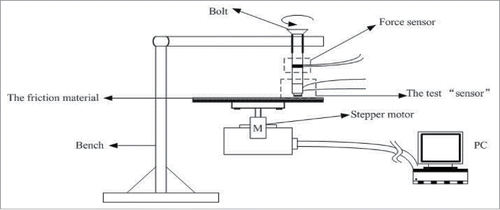
Figure 3. Flow diagram of the experiment. By sliding friction on the surface of objects and transferring tiny acoustic signal generated by the friction of PVDF film sand targeted materials into electrical signal according to the sonic transducer, the characteristics of acoustic signal for the corresponding materials were analyzed and some conclusions were presented.

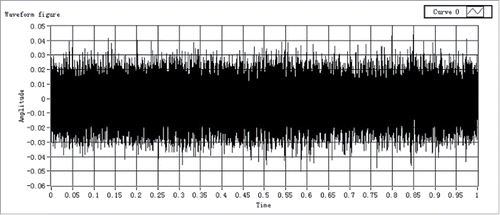
The device was used to assess the surface roughness of 3 different objects: an office desktop, printing paper, and a cardboard box.Citation15 Before the experiment commenced, the device recorded a set of empty data in order to check whether environment noise would affect the experimental data. The empty data also provided insight into whether the system had any major problems. depicts the original empty data.
shows a typical white noise signal with amplitude around ±30 mv, consistent with the expected results. The sensor was then rubbed against the 3 experimental objects at a pressure of 1 N and speed of 100 mm/s. The testing distance was maintained around 5 cm. The frequency, amplitude, and normal force of the rubbing motion did not appear to be critical for sound generation; therefore, these experimental parameters were kept consistent throughout the experiment to ensure reproducibility.
Spectrum analysis one of the most common analysis methods used in signal processing.Citation16 Identifiable information for the AE source eigen can be found by converting the AE signal from the time domain to the frequency domain. However, some complex acoustic signals have features that can only be reflected in the frequency domain. Theoretically, similar AE signals from similar sources have similar spectrum distribution characteristics, while AE signals from different sources contain essential information that reflects their features. Therefore, spectrum analysis can shed light on the the AE source signal and its dynamic characteristics.
Results and discussions
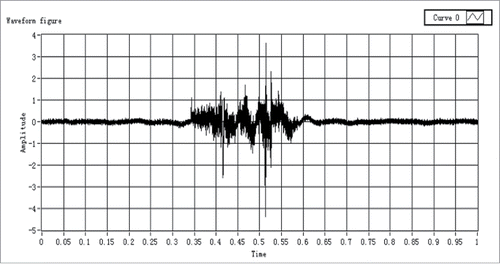
The tactile sensor was gently rubbed against one object repeatedly, and a time period when the waveform was relatively stable was selected as the data source. shows the waveform when the sensor rubbed against the printing paper.
Figure 5. Printing paper friction waveform. The tactile sensor was gently rubbed against the printing paper repeatedly, and a time period when the waveform was relatively stable was selected as the data source.
The tactile sensor was rubbed against the printing paper 3 times at the same pressure and speed. displays the spectrum diagram for the data from all 3 experiments calculated by the fast Fourier transform.
Figure 6. Multiple sampling. The tactile sensor was rubbed against the printing paper 3 times at the same pressure and speed. It is the spectrum diagram for the data from all 3 experiments calculated by the fast Fourier transform.
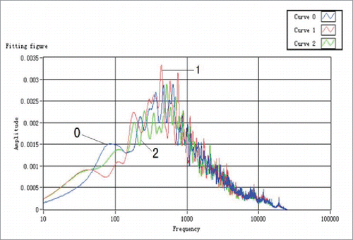
shows that the sizes and the change trends of the 3 curves are very similar to each other. The peak frequencies for curves 0, 1, and 2 are 475 Hz, 450 Hz, and 510 Hz, respectively, with corresponding peak values of 0.00282, 0.00318, and 0.00285. These data are reported in .
Table 1. Results of several tests.
Among the 3 curves, the maximum deviation of the peak frequency is 6.7%, and the maximum deviation of the peak value is 7.8%. Both of these values are below 10%, explaining the high reproducibility of the data. According to friction theory, no matter how smooth a contact surface is, contact between 2 materials is caused by a handful of convex points rather than the entire plane. Additionally, the contact points are not identical over time. Although the friction movement was performed repeatedly under the same circumstances, the 3 curves cannot be expected to look exactly alike.
shows typical acoustic spectra recorded when the tactile sensor was stroked against the 3 different materials. Curve 0 shows the data spectrogram produced by rubbing against the office desktop, curve 1 shows the data produced by rubbing against the printing paper, and curve 2 shows the data produced by rubbing against the cardboard surface. The acoustic signals cover the entire range of frequencies. Among these 3 sets of data, the frequency of curve 2 peaks around 130 Hz. The signal frequency bandwidth of curve 0 is wider than that of curve 2, and the peak frequency of curve 0 is about 300 Hz. The amplitude of curve 0 is clearly less than that of curve 2 below 200 Hz; however, in the range from 200 Hz to 800 Hz, the amplitude of curve 0 is greater than that of curve 2. Curves 0 and 2 attenuate to zero at almost the same rate after 800 Hz. The peak frequency of curve 1 is about 140 Hz, and the amplitude of curve 1 is clearly the lowest of the 3 curves below 360 Hz. In the range from 360 Hz to 4,000 Hz, the amplitude of curve 1 is higher than that of curve 2, and in the range from 600 Hz to 4,100 Hz, the amplitude of curve 1 is greater than that of curve 0. shows these statistics.
Figure 7. Spectrogram of experiment 1. Curve 0 shows the data spectrogram produced by rubbing against the office desktop, curve 1 shows the data produced by rubbing against the printing paper, and curve 2 shows the data produced by rubbing against the cardboard surface.
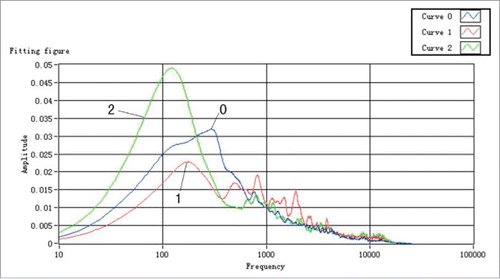
Table 2. Results of different materials.
After comparing and analyzing the curves, we determined that each curve has its own trend, which can be utilized to separate the curves from one another. According to the comparison, we can conclude that the roughness of the cardboard surface is greater than that of the office desktop, which is greater than that of the printing paper. These results are consistent with our daily experience. Therefore, the experiment demonstrates that the proposed sensor is capable of detecting surface roughness.
The pressure and the speed exerted on the sensor can also affect friction. To assess their influences on the results, we carried out the following 2 experiments.
Printing paper was selected as the friction object, and the friction speed was held constant at 5 cm/s. Normal pressure was applied at both 1 N and 3 N. shows the spectra resulting from the 2 trials.
Figure 8. Spectrogram of experiment 2. Curve 0 shows the spectrogram of data produced by rubbing with 1 N of pressure, while curve 1 shows the spectrogram produced by rubbing with 3 N of pressure.
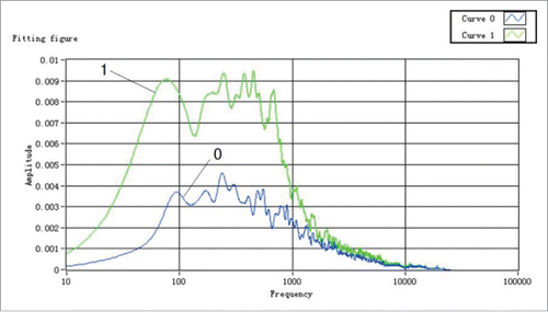
In , curve 0 shows the spectrogram of data produced by rubbing with 1 N of pressure, while curve 1 shows the spectrogram produced by rubbing with 3 N of pressure. The two curves have a high degree of similarity in shape, and the only difference is that the amplitude of curve 0 is less than that of curve 1 at the same frequency. The peak frequency of curve 0 is 239 Hz, with a peak value of 0.0046; meanwhile, the peak frequency of curve 1 is 245 Hz, with a peak value of 0.0094. The peak frequency deviation between the 2 curves is 2.5%, while the peak value deviation is 204%. These results suggest that the pressure magnitude has a greater effect on the curve's amplitude.
Next, the friction pressure was held constant at 2 N, and normal speed was applied at both 10 cm/s and 20 cm/s. shows the spectra resulting from the 2 trials.
Figure 9. Spectra with different normal speeds. Curve 0 shows the spectrogram of data produced by rubbing at a speed of 20 cm/s, while curve 1 shows the spectrogram produced by rubbing at a speed of 10 cm/s.
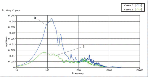
In , curve 0 shows the spectrogram of data produced by rubbing at a speed of 20 cm/s, while curve 1 shows the spectrogram produced by rubbing at a speed of 10 cm/s. The peak frequency of curve 0 is 135 Hz, and the corresponding peak value is 0.0424; meanwhile, the peak frequency of curve 1 is 75 Hz, and the peak value is 0.0129. The peak frequency deviation of the 2 curves is 80%, and the peak value deviation of the 2 curves is 329%. These results suggest that changes in friction speed have a greater effect on amplitude than on frequency.
According to the 2 experiments described above, the magnitude of the friction pressure and the friction speed affect both the peak frequency and the peak value.Citation17 However, no matter the value of the pressure and speed, both have greater effects on the amplitude value than on the frequency. Meanwhile, although the friction speed affects the peak frequency, the effect is far less dramatic than the effect produced by friction pressure after the contrast.
Conclusions
Measuring the acoustic signal produced by contact between 2 materials represents an innovative experimental tool to measure tribological and adhesive contact properties relevant to texture perception. Analysis of the resulting spectra allowed us to identify the frequency and amplitude characteristics of the friction signals, which can be used as a basis for distinguishing among different materials. Using the same kind of material, the influences of different friction velocities and friction load forces were analyzed, as these factors can also impact the signal. These experiments demonstrated the feasibility of using PVDF to detect surface roughness based on AE signals, which suggests that PVDF can be applied as a new sensitive material for use in robotic tactile sensors.
Disclosure of potential conflicts of interest
No potential conflicts of interest were disclosed.
Reference
- Chen W, Dong Y, Chen Y. Experiment and Research of a New Tactile and Slip Sensor. Yadian Yu Shengguang/Piezoelectrics & Acoustooptics 2010; 32(4).
- Gong X, Zhang RC, Zhang XH, et al. Review of the tactile sensor. Electronics Instrumentation Customer 2005.
- Dargahi J. Piezoelectric and pyroelectric transient signal analysis for detection of the temperature of a contact object for robotic tactile sensing. Sensor Actuat A-Phys 1998; 71:89-97.
- Seminara L, Capurro M, Cirillo P, et al. Electromechanical characterization of piezoelectric PVDF polymer films for tactile sensors in robotics applications. Sensors & Actuators A Physical 2011; 169(1):49-58.
- Zahouani H, Mezghani S, Vargiolu R, et al. Effect of roughness on vibration of human finger during a friction test. Wear 2013; 301(1–2):343-52.
- Vezzoli E, Ben MW, Amberg M, Giraud F, Lemaire-Semail B, Bueno MA. Physical and perceptual independence of ultrasonic vibration and electrovibration for friction modulation. IEEE Trans Haptics 2015; 8(2):235-9; PMID:25955993; http://dx.doi.org/10.1109/TOH.2015.2430353
- Pan XY, Ting HU, Liu FC, et al. Underactuated multi-fingered hand with tactile sensor hardware system based on PVDF. Journal of Mechanical & Electrical Engineering 2012.
- Roh Y, Varadan VV, Varadan VK. Characterization of all the elastic, dielectric, and piezoelectric constants of uniaxially oriented poled PVDF films. IEEE Trans Ultrasonics Ferroelectr Freq Control 2002; 49(6):836-47; PMID:12075977
- Azushima, A, Xue, WD, & Yoshida, Y. Effect of surface roughness of roll on coefficient of friction in hot rolling(forming processing and thermomechanical treatment). Tetsu- to- Hagane 2008; 94:134-40.
- Yan XQ, Xie ZL, Fan BS, Ming-Fu FU. Characteristics of friction-introduced acoustic emission based on the surface roughness. Mocaxue Xuebao/Tribology 2011; 31(6):587-91.
- Aken G A V. Acoustic emission measurement of rubbing and tapping contacts of skin and tongue surfaces in relation to tactile perception. Food Hydrocolloids 2013; 31(2):325-31.
- Bajpai V, Mahambare P, Singh RK. Effect of Thermal and Material Anisotropy of Pyrolytic-Carbon in Vibration-Assisted Micro-EDM Process. Materials & Manufacturing Processes 2015.
- Tanaka Y, Tanaka M, Chonan S. Development of a sensor system for measuring tactile sensation. Conference on Information, Intelligence and Precision Equipment: IIP. The Japan Society of Mechanical Engineers, 2004. 116-7.
- Bar HN, Bhat MR, Murthy C R L. Parametric Analysis of acoustic emission signals for evaluating damage in composites using a PVDF film sensor. J Nondestruct Eval 2005; 24(4):121-34; http://dx.doi.org/10.1007/s10921-005-8780-z
- Liu JM, Xiao-Long LV, Chun-Rui WU, et al. The study on the preparation for hydrophobic surface of PVDF hollow fiber membrane. Gongneng Cailiao/Journal of Functional Materials 2013; 44(14):2101-5.
- Meng XR, Zhang HZ, Huang DX, Liang Z, Lei W, Wang XD. Study on structure and properties of polybasic blend PVDF ultrafiltration membrane. Gongneng Cailiao/Journal of Funct Mater 2013; 44(5):660-4.
- Li Q, Xu ZL, Liu M. Preparation and characterization of PVDF microporous membrane with highly hydrophobic surface. Polym Adv Technol 2011; 22(5):520-31; http://dx.doi.org/10.1002/pat.1549

