Abstract
Theoretical prediction of the heterogeneous atomic structures in multicomponent alloys is one of the most challenging issues in materials science. Here we present a first-principles demonstration of this by constructing an on-lattice effective multibody potential model to describe the energetics of hexagonal close-packed Mg crystals containing stacking faults (SFs) with Al and Gd substitutions. Remarkably, we showed that our intuitive model can describe the segregation of solute atoms to SFs and reproduce the characteristic short-range chemical order in dilute Mg–Gd and Mg–Al–Gd systems, including long-period stacking ordered structures, in a manner consistent with recent scanning transmission electron microscopy measurements.
Alloying is important in the production of metallic materials for various scientific applications; it strengthens and enhances metal properties by adding other elements via processing at appropriate compositions and temperatures.[Citation1,Citation2] Due to their light weight, Mg-based alloys containing rare earth (RE) metals,[Citation3] especially Mg–M–RE alloys (M: main group or transition metal) with long-period stacking ordered (LPSO) phases,[Citation4,Citation5] have recently been receiving increased attention because of their outstanding mechanical performances with high yield strength and ductility, which are believed to result from the formation of characteristic microstructures with solute-rich zones; in particular, LPSO phases are known to comprise stacking faults (SFs) at regular intervals where the solute atoms are enriched and even ordered due to their dissolving and binding nature in the matrix. However, because of the lack of experimental observations and theoretical models, details on the fundamental mechanism of solute-atom concentration and clustering at the atomic level have not yet been established.
To properly assess the role of solute-rich zones in the resultant strengthening behavior, identifying and clarifying the controlling factors for the formation and stabilization of solute-atom arrangements in the matrix system are necessary. Predicting the structure at the atomic level, especially in multicomponent systems, remains a fundamental challenge in condensed matter science.[Citation6] State-of-the-art technologies for electron microscopy and imaging—for example, recent advances in high-angle annular dark-field scanning transmission electron microscopy (HAADF-STEM) techniques—have improved our fundamental understanding of the variation in composition and crystal phase containing an ordered arrangement of solute atoms in Mg-based alloys.[Citation5,Citation7–10] However, due to the limited sensitivity and spatial resolution, not all the features of ordering of solute atoms are expected to be readily discernible.
We propose an effective multibody potential model that defines lattice systems of dilute Mg–M–RE ternary alloys while considering the change in stacking of the close-packed planes to provide a theoretical framework for finding energetically favorable configurations from a bottom-up point of view. As an example, the Mg–Al–Gd system was parameterized based on first-principles density functional theory (DFT) calculations in an unambiguous manner, i.e. without any curve fitting. We applied this to atomistic Monte Carlo modeling to predict the segregation and clustering of solute atoms in the system and confirmed its validity by comparison with experimental results.[Citation8,Citation9]
To examine the solid solution properties of Mg–Al–Gd alloy crystals containing SFs, we performed total-energy minimization calculations using the Vienna ab-initio simulation package [Citation11] with the projector-augmented-wave (PAW) construction for pseudopotentials.[Citation12,Citation13] PAW potentials are constructed so that the 3s electrons for Mg, 3s and 3p electrons for Al, and 5p, 5d, and 6s electrons for Gd are treated as valence electrons, and the remaining electrons are kept frozen. The exchange-correlation functional was parameterized in terms of Perdew and Wang's generalized gradient approximation.[Citation14] A plane-wave basis set with 300.5 eV energy cutoff was adopted. We employed (where a0=3.19 Å and c0=5.18 Å are the lattice constants of the relaxed hexagonal Mg) orthorhombic supercells of Mg containing 96 atoms with different stacking sequences—hexagonal close-packed (hcp), face-centered cubic (fcc), single (type I1) and double (type I2) intrinsic SFs, etc.—in which 1–3 Mg atoms are replaced by Al and/or Gd atoms (see Supplementary Materials section). We applied a
Monkhorst–Pack k-mesh [Citation15] to carry out Brillouin-zone integration using the Methfessel–Paxton smearing method [Citation16] (width: 0.2 eV) for ionic relaxations while using the tetrahedron method with Blöchl correction [Citation17] to determine the total energies (E). The E values used as a reference were for relaxed states: the atomic positions and cell parameters are relaxed until their residual forces converge to less than 3 meV/Å.
The binding energies of the solute to the SF and the solute–solute pair (Eb) and the formation energies for the target system (Ef) are defined as follows:
The solute binding to the SFs in Mg can be quantitatively characterized by the values listed in , which correspond to the difference between the dissolution energies of the solute atom in the hcp layer and in the faulted layer. Al and Gd dissolved in fcc-Mg more preferably than in hcp-Mg; in particular, the Gd-binding to the SFs was remarkable.
eV at the type I1 (hċh stacking) SF plane and
eV at the type I2 (hċch stacking) SF plane. Moreover, the binding energies of Al and Gd distinctly depend on the difference in stacking sequence of Al/Gd-substituted layers. It is noteworthy that favorable binding of Al and Gd was clearly observed even at normal hcp layers neighboring SFs, e.g. at the middle layer of ‘hḣc’ stacking, but the strength of the solute binding is weaker at the outer hcp layers than at the inner fcc layers of I2-type SFs, as shown in . This indicates that the energetics of the dissolution and binding of Al and Gd in Mg is affected by changes in the stacking sequence over at least five neighboring layers along the [Citation0001] direction.
Table 1. Binding energies (in eV) between a solute atom (Al or Gd) and SF in the Mg lattice.
The binding energies between various solute pairs () at the 1nn, 2nn, and 3nn positions were also evaluated in the hcp-Mg matrix (). For the Al–Al pairs in hcp-Mg, all Eb values at the 1nn, 2nn, and 3nn distances were negligibly small; thus, the Al–Al binding is not a significant factor in the solute concentration. However, interactions between Al–Gd pairs at the 1nn positions are attractive, i.e.
eV, where the local strain around the pair can be reduced by combining the atoms of different elements with small and large atomic radii. Gd–Gd binding was found to be repulsive at the 1nn distance but considerably attractive at the 2nn and 3nn ones, i.e.
and −0.10 eV, respectively. This indicates that combinations of 1nn Al–Gd pairs and 2nn and/or 3nn Gd–Gd pairs are possible candidate units for the formation of local ordered clusters in Mg–Al–Gd systems.
Table 2. Binding energies (in eV) for the 1nn, 2nn, and 3nn solute–solute pairs in the hcp-Mg matrix.
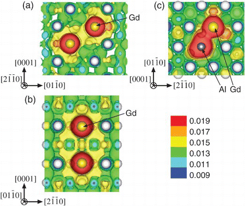
To confirm the origin of attractive interactions between the solute atoms, charge density distributions around the 1nn Al–Gd and 2nn/3nn Gd–Gd pairs in the hcp-Mg system were analyzed (). The large accumulation of electrons around the Al and/or Gd atoms and their joined shape suggest the presence of chemical interactions that lead to such strong binding energies. It is obvious that the Al–Gd and Gd–Gd pairs in Mg show binding features that may lead to the cross-linked distribution of charge density between the solute atoms. This implies that the binding nature of these solute pairs contributes to steady growth of short-range ordering and clustering among the solute atoms.
Figure 1. Charge density distributions around the (a) 2nn Gd–Gd, (b) 3nn Gd–Gd, and (c) 1nn Al–Gd pairs in the hcp-Mg matrix. White, gray, and yellow spheres represent Mg, Al, and Gd atoms, respectively.

To describe such characteristics concerning the energetics and configurations of the solute atoms, a multibody interatomic potential model for the Mg–M–RE system was constructed that considers the dependence of the strength of pair interaction with the local environment (i.e. bond order effect) in a simplified manner. We describe the potential of the system U as an approximation of the formation energy Ef in the form
In the present model, U3body and Umbody are introduced as correction terms to the two-body additive approximation for the formation energy. The U3body term has the following form:
The Umbody term has the following form:
Eventually, all potential parameters described above were obtained from relations concerning the binding and formation energies of the system listed in –. For more details on the potential parameterization, please refer to the Supplementary Materials section.
Table 3. Reproduction and prediction of formation energies (in eV) from the Mg–M–RE interaction potential developed in this study compared to those from our ab initio DFT calculations.
To prove the validity and effectiveness of the developed potential, thermal equilibrations of the Mg–Gd and Mg–Al–Gd systems with and without SFs were carried out by using Markov chain Monte Carlo (MCMC) simulations.[Citation18] To accelerate the sampling process for such complex multicomponent systems, we employed the MCMC method without detailed balance.[Citation19] For the equilibrium simulations of the Mg–Gd and Mg–Al–Gd supersaturated solid solutions, orthorhombic supercells of Mg containing 1344 atoms with 2H stacking were used. As an initial configuration, solute atoms were randomly distributed on the sites of a hcp lattice with a composition of Mg–5.4at%Gd (
), Mg–12.5at%Gd (
), Mg–4.0at%Al–5.4at%Gd (
), and Mg–9.4at%{ }Al–12.5at%Gd (
) with an Al/Gd ratio of ¾. The simulations starting from multiple (typically five) initial configurations with different sets of random positions of solute atoms were conducted for 5×10⁶ steps at 500 K via successive swapping of neighboring pair elements under periodic boundary conditions.
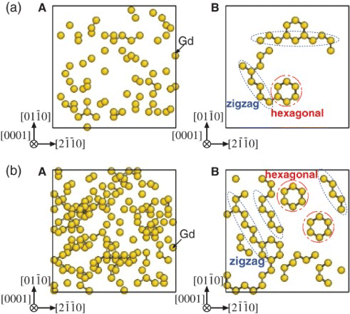
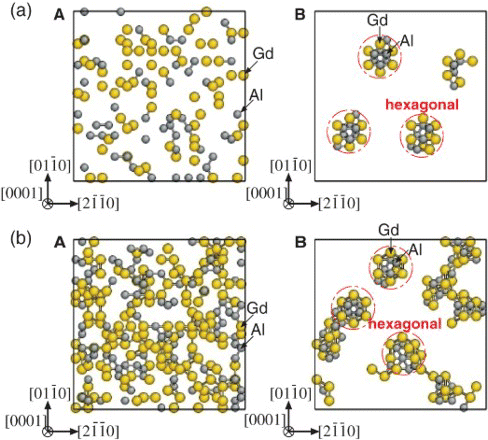
For the Mg–Gd system (), two kinds of characteristic local clusters were observed: linear zigzag patterns (along the direction) and localized hexagonal patterns. These corresponded to local structures of β′-Mg7Gd (base-centered orthorhombic) [Citation7] and
(D019), respectively. Both are arranged from 2nn and 3nn Gd–Gd pairs, and the coexistence of the two kinds of short-range orders (corresponding to β″ phase) was experimentally observed by HAADF-STEM images of an Mg–5at%Gd alloy at early stages of aging at 200°C.[Citation8] The linear zigzag patterns became dominant over the hexagonal ones as the aging time increased as a reflection of the lower formation energy of the β′ structure than that of the D019-type structure (see Supplementary Materials section). For the Mg–Al–Gd system (), the linear zigzag patterns disappeared, and only rather isolated hexagonal patterns survived. Note that the Al enrichment was distinctly confined inside the hexagonal arrangements formed by the 2nn and 3nn Gd–Gd pairs. This indicates that the addition of Al stabilizes the local D019-type structure because the energy gain by the formation of 1nn Al–Gd pairs overcomes the energy loss caused by the change in Gd arrangements with high
.
Figure 2. Solute clusters distribution for the (a) Mg–5.4at%Gd and (b) Mg–12.5at%Gd alloy systems with 2H stacking projected on the (0001) plane. Only Gd atoms are displayed in yellow spheres. (A) Initial configuration with all atoms distributed randomly over the hcp lattice. (B) Clustering because of a 5×10⁶-step MCMC run at 500 K. Bars between the solute atoms represent the 2nn Gd–Gd pairs.

Figure 3. Solute clusters distribution for the (a) Mg–4.0at%Al–5.4at%Gd and (b) Mg–9.4at%Al–12.5at%Gd alloy systems with 2H stacking projected on the (0001) plane. Only solute atoms are displayed: Gd atoms in yellow and Al atoms in gray spheres. (A) Initial configuration with all atoms distributed randomly over the hcp lattice. (B) Clustering because of a 5×10⁶-step MCMC run at 500 K. Bars between the solute atoms represent the 1nn Al–Gd pairs.

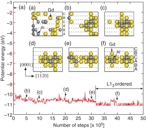
We performed MCMC simulation of the Mg–Al–Gd system with an SF by employing a monoclinic supercell of Mg containing 144 atoms with 18R stacking, where an I2 SF was introduced in the middle of six atomic layers (i.e. hhcchh). At the beginning of the simulation, solute atoms were randomly distributed on the sites of a lattice with a composition of Mg–8.3at%Al–11.1at%Gd (). and the supplemental movie (SupplMovie.mpg) show that solute atoms gathered near each other due to the formation of 1nn Al–Gd and 2nn Gd–Gd pairs and also gradually segregated into the SF layer during the configuration sampling. The formation and in-plane alignment of L12-type solute clusters (Al6Gd8×2) were clearly achieved after equilibration of the system, which is completely consistent with recent HAADF-STEM measurements for the Mg–Al–Gd LPSO phases.[Citation9] The obtained L12-ordered configuration was not a fitting target in the development of our potential model but was predicted.
Figure 4. Evolution of potential energy for the Mg–Al–Gd alloy system with 18R stacking at 600 K. The inset shows snapshots of the simulated solute atom clusters during MCMC sampling.

lists the formation energies of the various Mg–Al–Gd configurations obtained from the potential developed here. We found that this interaction potential provides reasonable agreement with the results from the DFT calculations. The Umbody term (i.e. f(1) and f(2)) proposed here played a crucial role in reproducing the energetics of the various Mg–Al–Gd configurations. This suggests that this term pertinently extracts the essential features of the inherent multibody nature of the dilute Mg–M–RE system and that the complex and cooperative interactions in the system can be characterized and understood from the viewpoint of the cubicity and chemical occupancy in the local environment with a range of 2r(1)=6.4 Å at most. In this study, the effects of long-range interactions (>6.4 Å) on the system were omitted and thus the energetic preference between the different stacking polytypes in the LPSO phases [Citation9] was not distinguished. The analysis about the effect of such interactions on the formation of long-period stacking and chemical order will be the subject of the future work.
We confirmed that our approach can successfully describe the formation and arrangement of Al/Gd clusters in a system and provide clear-cut insights into the short-range chemical order in Mg-based alloys, including LPSO structures, by taking into account the identified multibody effects on the system. The considerable agreement between the ab initio potential-based predictions and HAADF-STEM images is encouraging with regard to predictive validity as a physics-based framework for alloy exploration and explanation; this will help improve our understanding of these multicomponent systems and provide further clarity on the organizing principles that govern local atomistic ordering in various alloy systems. We firmly believe that such efforts will open a new design space in the advanced alloy engineering.
Supplementary online material
A more detailed information on calculations is available at http://dx.doi.org/10.1080/21663831.2013.838705.
Supplementary_Material.zip
Download Zip (7.3 MB)Acknowledgements
This study was supported by Grants-in-Aid for Scientific Research on Innovative Area, No. 23109004; Young Scientists (A), No. 24686072; Scientific Research (A), No. 23246025; and Challenging Exploratory Research, No. 25630013. We also appreciate the support from the Elements Strategy Initiative for Structural Materials, No. 22656030, and useful discussions with M. Fronzi.
References
- Clouet E, Laé L, Épicier T, Lefebvre W, Nastar M, Deschamps A. Complex precipitation pathways in multicomponent alloys. Nat Mater. 2006;5:482–488. doi: 10.1038/nmat1652
- National Science and Technology Council. Materials genome initiative for global competitiveness. Washington, DC; 2011.
- Rokhlin LL. Magnesium alloys containing rare earth metals: structure and properties. London: Taylor & Francis; 2003.
- Kawamura Y, Hayashi K, Inoue A, Masumoto T. Rapidly solidified powder metallurgy Mg97 Zn1 Y2 alloys with excellent tensile yield strength above 600 MPa. Mater Trans. 2001;42:1172–1176. doi: 10.2320/matertrans.42.1172
- Abe E, Ono A, Itoi T, Yamasaki M, Kawamura Y. Polytypes of long-period stacking structures synchronized with chemical order in a dilute Mg–Zn–Y alloy. Philos Mag Lett. 2011;91:690–696. doi: 10.1080/09500839.2011.609149
- Woodley SM, Catlow R. Crystal structure prediction from first principles. Nat Mater. 2008;7:937–946. doi: 10.1038/nmat2321
- Nishijima M, Hiraga K, Yamasaki M, Kawamura Y. Characterization of β′ phase precipitates in an Mg–5at%Gd alloy aged in a peak hardness condition, studied by high-angle annular detector dark-field scanning transmission electron microscopy. Mater Trans. 2006;47:2109–2112. doi: 10.2320/matertrans.47.2109
- Nishijima M, Hiraga K. Structural changes of precipitates in an Mg–5at%Gd alloy studied by transmission electron microscopy. Mater Trans. 2007;48:10–15. doi: 10.2320/matertrans.48.10
- Yokobayashi H, Kishida K, Inui H, Yamasaki M, Kawamura Y. Enrichment of Gd and Al atoms in the quadruple close packed planes and their in-plane long-range ordering in the long period stacking-ordered phase in the Mg–Al–Gd system. Acta Mater. 2011;59:7287–7299. doi: 10.1016/j.actamat.2011.08.011
- Kishida K, Yokobayashi H, Inui H, Yamasaki M, Kawamura Y. The crystal structure of the LPSO phase of the 14H-type in the Mg–Al–Gd alloy system. Intermetallics. 2012;31:55–64. doi: 10.1016/j.intermet.2012.06.010
- Kresse G, Furthmüller J. Efficient iterative schemes for ab initio total-energy calculations using a plane-wave basis set. Phys Rev B. 1996;54:11169–11186. doi: 10.1103/PhysRevB.54.11169
- Blöchl PE. Projector augmented-wave method. Phys Rev B. 1994;50:17953–17979. doi: 10.1103/PhysRevB.50.17953
- Kresse G, Joubert D. From ultrasoft pseudopotentials to the projector augmented-wave method. Phys Rev B. 1999;59:1758–1775. doi: 10.1103/PhysRevB.59.1758
- Perdew JP, Chevary JA, Vosko SH, Jackson KA, Pederson MR, Singh DJ, Fiolhais C. Atoms, molecules, solids, and surfaces: applications of the generalized gradient approximation for exchange and correlation. Phys Rev B. 1992;46:6671–6687. doi: 10.1103/PhysRevB.46.6671
- Monkhorst HJ, Pack JD. Special points for Brillouin-zone integrations. Phys Rev B. 1976;13:5188–5192. doi: 10.1103/PhysRevB.13.5188
- Methfessel M, Paxton AT. High-precision sampling for Brillouin-zone integration in metals. Phys Rev B. 1989;40:3616–3621. doi: 10.1103/PhysRevB.40.3616
- Blöchl PE, Jepsen O, Andersen OK. Improved tetrahedron method for Brillouin-zone integrations. Phys Rev B. 1994;49:16223–16233. doi: 10.1103/PhysRevB.49.16223
- Frenkel D, Smit B. Understanding molecular simulation: from algorithms to applications. 2nd ed. San Diego: Academic Press; 2002.
- Suwa H, Todo S. Markov chain Monte Carlo method without detailed balance. Phys Rev Lett. 2010;105:120603-1–4. doi: 10.1103/PhysRevLett.105.120603