
Abstract
Controlling phase growth during solidification is essential to obtain desirable structures and properties in metallic materials by casting. However, only limited ways are available for controlling the growth of phases during solidification. Here, we report a general approach to control the growth of phase domains during solidification by adsorption of nanoparticles on the growing interface. The effectiveness of the approach is demonstrated in an Sn–Al alloy. With nanoparticle-enabled growth control, the size of the primary Al phase is reduced substantially and the dendrite growth is restricted. This work potentially provides an effective way to control the structure of alloys during solidification.
Solidification processing is a basic, simple and economical way to obtain various metallic materials and parts.[Citation1–7] It is well known that the properties of materials are dictated by their microstructures. Thus, controlling the microstructure evolution during solidification is essential. If we can control the microstructure of as-cast materials to the extent we want, the costly and time-consuming heat treatment (solution heat treatment, precipitation treatment, etc.), and plastic deformation processing (rolling, extrusion, forging, etc.) can be minimized or even eliminated. Furthermore, in many situations, we would only use the as-solidified materials, such as in welding and soldering. The properties of materials in these applications cannot be improved by post-solidification plastic deformation processing. Therefore, our ability to control the as-solidified structure determines the properties available in these materials. Moreover, controlling the microstructure during solidification is also important for the solidification processing itself. For example, a globular primary phase is a prerequisite for semisolid processing [Citation8,Citation9]; the refined intermetallic phase is required for avoiding hot tearing during casting of the alloys with a wide solidification range.[Citation10] Effective microstructure refinement during solidification also brings many direct and indirect benefits for wrought alloys, such as the possibility of faster production rates.[Citation11]
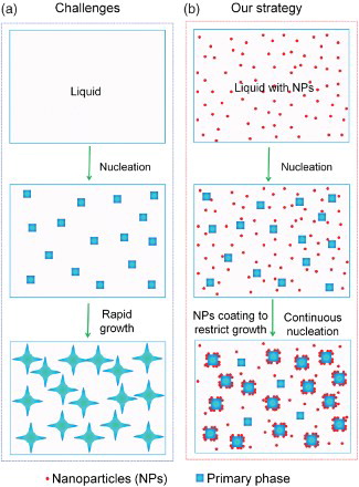
However, to control the microstructure of materials during solidification is difficult. The key challenge for microstructure control during solidification is the fast phase growth, as schematically shown in (a). Due to the high diffusion coefficient in liquid metal and the high supersaturation encountered in most alloys, the growth speed of the solidification front is very fast, from micrometer per second to millimeter per second.
Figure 1. Schematic of the strategy to control phase growth by nanoparticles during solidification. (a) After the initial nucleation of the primary phase from liquid, the initially nucleated grains/phase domains grow rapidly and release latent heat, preventing the nucleation of new grains/phase domains. This results in a course structure. (b) In contrast, with uniform dispersed nanoparticles in the liquid, after initial nucleation, the nanoparticles rapidly adsorb on the surface of the nucleated phase and restrict their growth, enabling continuous nucleation in the whole period of cooling. Finally, a much fine microstructure can be achieved.
To control the microstructure of materials during solidification, the commonly used way is to adjust the cooling rate. By increasing the cooling rate, a fine microstructure can be achieved.[Citation12,Citation13] However, due to the growth speed significantly increasing with an increase in the cooling rate, to get fine microstructure, thousands to millions of kelvin per second is needed.[Citation14] The size of the as-solidified sample and the processing window time are severely restricted to micrometers (at least in one dimension) and milliseconds, respectively, substantially restricting the size and complexity of the products.
Another widely used way to control the structure of materials during solidification is using a grain refiner to nucleate more grains at the beginning of the solidification. By increasing the number of grains in the solidified material, the size of the grain is reduced. However, the grain-refining efficiency (number of grains per number of inoculant particles) by inoculant particles is very low; usually only less than 1% of the added particles successfully nucleate grains; and the grain-refining efficiency decreases rapidly with an increase in the number of added particles.[Citation11,Citation15,Citation16] The limited grain-refining efficiency achievable by inoculation is mainly due to the fast crystal growth from the nuclei formed early.[Citation15] The fast growth of the grains nucleated first will release heat and increase the temperature of the surrounding melt immediately. Consequently, the inoculant particles in the surrounding melt do not have a chance to nucleate new grains, due to a lack of sufficient undercooling. Thus, the spontaneous nucleation of high-density grains is usually not practical. The minimum grain size achievable in engineering alloys by inoculation can only down to tens of micrometers in common solidification practice.[Citation17] Thus, the key to control the microstructure during solidification is to slowdown the growth of the phases.
Adsorption of nano-sized precipitates on the surface of a growing phase is an interesting and effective way to modify the structure of materials during solidification. The adsorbed nano-sized precipitates on the surface of the growing phase can modify both the size and morphology of the phase. For example, strontium can modify the morphology and size of silicon phase in Al–Si alloy by precipitation of strontium cluster on the surface of the silicon phase during solidification.[Citation18] However, this method is only occasionally successfully used in a few alloys with specific compositions, due to the difficulty to get fine precipitates.[Citation19]
Recently, we developed an approach to rapidly control the phase domain growth through blocking diffusion by densely packed nanoparticles on the growing interface.[Citation20] In this paper, we will show that, in addition to blocking diffusion, the growth of solid-phase domains during solidification can be controlled through modifying the temperature and/or solute concentration field, increasing the free energy of the growing phase, and pinning down the growth front by adsorption of nanoparticles on the growing interface. A dense coating of nanoparticles on the growing interface is not needed for controlling the growth of solid-phase domains. (b) schematically shows our approach to control the growth of solid-phase domains during solidification by using thermal and chemical stable nanoparticles. The thermally and chemically stable nanoparticles are incorporated and dispersed uniformly in molten metal. Driven by the reduction of total interfacial energy, during solidification, the nanoparticles rapidly adsorb on the surface of the nucleated phase to restrict the further growth of the phase. The effective growth restriction will allow other nearby nuclei to survive and enable continuous nucleation in the whole period of solidification.[Citation20] With the fast and effective growth control, the fine microstructure can be obtained in as-cast materials at a low cooling rate. The effectiveness of this strategy is demonstrated in a simple Sn–6.8Al (wt.%) eutectic alloy.
The Sn–6.8Al alloy was selected as a model system to study the growth of the primary phase due to the simplicity of this alloy, as shown in Figure S1(a).[Citation21] Since the eutectic point is very close to Sn, the primary Al phase dominates the Al phase, which facilities the study of the primary Al phase. The TiC0.7N0.3 particles with an average diameter of about 80 nm (from Sigma-Aldrich, shown in Figure S1(b)) were selected for this study because of their good thermal and chemical stability in Al–Sn alloy melt, good lattice match with aluminum (indicating a low interfacial energy between nanoparticle and aluminum), smaller particle size and availability from the market.[Citation20]
The Sn–6.8Al alloy melt was prepared by melting commercial pure tin (99.9%, Alfa Aesar) and aluminum (99.5%, AA1350) in an alumina crucible using an electrical resistance furnace. TiC0.7N0.3 nanoparticles (shown in Figure S1(b), with a diameter of less than 150 nm and an average diameter of about 80 nm, from Sigma-Aldrich), were fed and dispersed into the molten metal by an ultrasonic cavitation-based method.[Citation22,Citation23] After ultrasonic processing, the crucible was taken out of the furnace. The Sn–6.8Al melt with nanoparticles was cooled down inside the crucible in air. For comparison, the pure Sn–6.8Al alloy was also prepared under the same conditions (except no nanoparticles). We measured the cooling rate by inserting thermocouples inside the melt during cooling. The cooling rate before solidification is about 1 K/s. To get various high cooling rates, we cast the melt into a wedge copper mold. The cooling rates at different locations are calculated from the thickness of the sample based on an empirical equation.[Citation24] After solidification, the morphology and size of the primary Al phase were studied by FESEM (field-emission scanning electron microscopes, Zeiss LEO 1530) by using an SE2 detector. The structure of the Al phase was studied by electron backscattering diffraction (EBSD). The nanoparticle distribution was investigated by FESEM by using an in-lens detector. More details of experimental procedures are described in Supplementary Section 1 and Figure S2.
The morphology of the primary Al phase in Sn matrix was studied by SEM. To show the Al phase clearly, we use ion milling to preferentially remove Sn from the surface of the SEM samples. (a) shows that the primary Al phase grows to a huge dendrite-like structure in pure Sn–6.8Al during solidification at a cooling rate of about 1 K/s. In contrast, the huge dendrite-like structure is absent in the sample with 2 vol% of TiCN nanoparticles prepared under the same conditions. The primary Al forms a cluster-like structure, uniformly distributed in the Sn matrix, as shown in (d). The size of the Al cluster in Sn–6.8Al + 2 vol% TiCN nanoparticles sample is much smaller than the size of the huge dendrite in pure Sn–6.8Al. The connected arms are clearly observed in the pure Sn–6.8Al sample, as shown in (b). However, the Al phase domains in cluster-like structure in Sn–6.8Al + 2 vol% TiCN nanoparticles sample are separated. To confirm that the separated Al phase domains in the cluster are not dendrite arms of a huge grain connected somewhere inside the sample, we investigated the structure of the Al phases by EBSD. The EBSD can detect the orientation of the atomic lattice. The different atomic lattice orientations are shown in different colors in the EBSD image. Therefore, the dendrite arms of a single grain should show the same color in the EBSD image. Thus, we can use the EBSD image to check whether the Al phases in the cluster-like structure are parts of a huge grain. (f) shows the EBSD image of the Al cluster marked by a black square in (e). The different color of the each part in the cluster confirms that they are separated individual grains. In contrast, the main part of the dendrite-like structure in the pure alloy shows the same color, indicating that they are parts of one big grain, as shown in (c). Interestingly, we also find that two branches of the dendrite-like structure show different colors. This indicates that the floating Al phases in liquid metal are prone to coagulate.
Figure 2. The morphology and structure of the Al phase and distribution of nanoparticles. (a–f) The morphology and structure of the Al phase in Sn–6.8Al with 0 (a–c) and 2 vol.% of TiC0.7N0.3 nanoparticles (d–f). Dark phases in (a), (b), (d) and (e) are Al, taken by an SE2 detector; (c) and (f) are EBSD images (different color indicates different grains). (g) SEM image of the interface region between primary aluminum and tin matrix in Sn–6.8Al with 2 vol.% of the TiCN nanoparticles sample, showing distribution of nanoparticles (NPs). The white circle highlights one nanoparticle inside the Al phase. To see nanoparticles clear, the image is taken by in-lens detector. (e) EDS spectrum of the particles in (g).
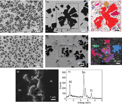
To understand the role of nanoparticles on growth of the primary Al phase, the distribution of nanoparticles was studied by SEM using an in-lens detector. (g) shows the SEM image of the Al–Sn interface region. The nanoparticles are clearly seen in the interface region. Most of the nanoparticles are on the surface of the Al phase; the nanoparticles are only occasionally found inside the Al phase, as marked by a white circle in (g). The nanoparticle coating on the Al phase is not fully complete and dense. The surface of the Al phase with high density of nanoparticles is concave, whereas the area with low density of nanoparticles is convex. This indicates that nanoparticles influence the growth of the Al phase during solidification. The energy-dispersive X-ray spectroscopy (EDS) spectrum of the nanoparticles region shows the strong Ti peak, indicating that the nanoparticles we observed are the nanoparticles we put in, as shown in (h).
The effects of cooling rate of up to 1000 K/s on the morphology of the Al phase and on the formation of nanoparticles coating on the surface of the Al phase were also studied. With incorporation of nanoparticles, the size of the Al phase is substantially refined, as shown in . Furthermore, the morphology of the Al phase changes from dendrite structure in pure alloy to nearly spherical particles in samples with nanoparticles.
Figure 3. The morphology and size of the primary Al phase and distribution of nanoparticles in fast cooled samples. (a) The SEM image of pure Sn–6.8Al cooled at 20 K/s; (b,c) SEM images of Sn–6.8Al with 2 vol.% TiCN nanoparticles at low (b) and high (c) magnifications cooled at 20 K/s; (d) The SEM image of pure Sn–6.8Al cooled at 1000 K/s; (e) SEM images of Sn–6.8Al with 2 vol.% TiCN nanoparticles cooled at 1000 K/s. (f) The size of primary Al phase versus cooling rate. Since the distribution of nanoparticles and the size of the Al phase in the sample cooled at 1 K/s are uniform, there is no data point for less NPs region in (f).
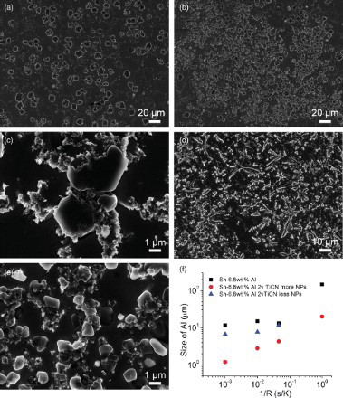
Even though the Al phase tends to form more branched dendrite structure in pure alloy with an increase in the cooling rate from 20 K/s to 1000 K/s, the nanoparticles still effectively modified the Al phase to nearly spherical particles at 1000 K/s, as shown in (d) and 3(e). This indicates that nanoparticles can quickly adsorb on the surface of the growing Al phase to control the growth of the primary Al phase. We also found that some Al phases in samples with nanoparticles are much larger than the average value. A careful analysis shows that these larger Al phases are free of nanoparticle coating. The morphology and size of the larger Al phase are comparable to those in pure alloy, as shown in (f). This further confirms that the adsorption of nanoparticles on the growing interface is essential for the modification of the primary Al phase.
The origin of the modification of Al phase domains by adsorbed nanoparticles was investigated. The concave surface of the primary Al phase associated with nanoparticle coating (in (g)) implies that the TiCN nanoparticles restrict the growth of the primary Al phase during solidification. The growth restriction may result from the modification of both thermodynamics and kinetics of the Al phase growth by TiCN nanoparticles. Several possible mechanisms of growth restriction are discussed below.
The first mechanism is the modification of the temperature and/or solute concentration fields around the solidification front by nanoparticles. When nanoparticles approach the solidification front, the nanoparticles may affect the local temperature and/or solute concentration fields, which influence the growth of the Al phase, as shown in (a). The lower thermal conductivity of the nanoparticles inhibits the removal of the latent heat from the solidification front and therefore restricts the growth of the phase; the nanoparticles can also block the solute diffusion away from the solidification front, thereby restricting the phase growth.[Citation25]
Figure 4. Mechanisms of growth restriction by nanoparticles. (a) Modifying temperature and/or solute concentration fields, (b) blocking diffusion, (c) increasing energy of growing phase, (d) step pining by the Gibbs–Thomson effect, (e) The SEM image of the concave surface of Al phase around nanoparticles, (f) The SEM image of curved surface between two nanoparticles.
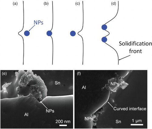
The second mechanism is blocking of diffusion and attachment of atoms to the surface of the growing phase by the adsorbed nanoparticles. When nanoparticles touch the solidification front and adsorb on the solid–liquid interface, the nanoparticles will block the transportation of the atoms to the solidification front.[Citation20] Thus, the growth of the phases at the area with nanoparticles adsorption is stopped, as schematically shown in (b). (e) shows a direct evidence of the growth restriction by adsorption of nanoparticles on the primary Al surface. The nanoparticle-free part of the surface of the Al phase is flat. However, the area with adsorbed nanoparticles exhibits an indent, as shown in (e). This clearly demonstrates the growth restriction by nanoparticles, highly possible due to the blocking of diffusion of Al atoms to the solidification front by the adsorbed nanoparticles.
The third possible mechanism is increasing the free energy of the growing phase by nanoparticles capture. When nanoparticles are incorporated into the growing phase through nanoparticle capture, the free energy of the growing phase usually increases due to the nanoparticle-induced distortion in the growing phase. This will lower the driving force for the phase growth and therefore slow down the phase growth, as schematically shown in (c).
The fourth mechanism is growth front pinning by nanoparticles through the Gibbs–Thomson effect. The molar free energy increase due to the interface curvature is known as the Gibbs–Thomson effect. The molar free energy increase depends on the radius of the curvature of the interface [Citation26]:
where
is the molar free energy increase, γ is the interfacial energy of the interface, r is the radius of curvature of the interface, and Vm is the molar volume of the phase. When multiple separated nanoparticles adsorb on the solidification front, the Al phase can only grow through the space between the nanoparticles to form a curvature with a much smaller radius, which results in an increase in
. If the distance between the adsorbed nanoparticles is less than a critical value, the growth of the Al phase stops at current undercooling and/or supersaturation, as schematically shown in (d). The curved interface between the two nanoparticles in (e) shows the evidence of growth front pinning by nanoparticles through the Gibbs–Thomson effect.
The above discussions show that the nanoparticles can restrict the growth of the primary Al phase by several mechanisms through modifications of both thermodynamics and kinetics of the phase growth. This indicates that the nanoparticles are very effective in controlling the growth of solid phases. However, to quantify the growth restriction effect enabled by each mechanism is a challenge, and will be studied in the future.
Nanoparticles can work as a grain refiner to refine the grain size by nucleation of more grains. A previous study has shown that TiCN nanoparticles could refine the Al phase due to the good lattice match between TiCN and Al.[Citation27] Thus, inoculation of the Al phase by TiCN nanoparticles is another possible contribution to the modification of the Al phase in the Sn matrix we observed. To roughly estimate the contribution of the inoculation on the size and morphology of the primary Al phase, we incorporated and dispersed 0.2 vol% of TiCN nanoparticles into the Sn–6.8Al melt. This amount of nanoparticles is enough for inoculation,[Citation27] but not enough for the growth restriction of the primary Al phase. As discussed in Supplementary Information Section 2 and Figure S3, the TiCN nanoparticles can work as a nucleation agent to moderately refine the primary Al phase, but the primary Al phases still show large dendrite arms. This indicates that inoculation alone cannot achieve the size and morphology modification shown in and . The growth restriction by nanoparticles should be the major contribution to the substantially modified structure in the Sn–6.8Al + 2 vol.% TiCN nanoparticles sample.
The adsorption of nanoparticles on the solidification front is essential for nanoparticle-enabled growth control. The driving force for the adsorption of nanoparticles to the solid–liquid interface is the reduction of the total interfacial energy of the system resulting from the reduction of interfacial area between the growing phase and liquid matrix due to the presence of particles at the growing interface.[Citation20] However, to quantify the driving force for adsorption is extremely hard due to the lack of interfacial energy data from open literatures,[Citation28–32] and the difficulty to accurately measure the interfacial energies of the nanoparticle–solid metal interface and nanoparticle–liquid metal interface. Extensive effort is needed in the future.
In summary, with incorporation and dispersion of 2 vol% of TiCN nanoparticles into the Sn–6.8Al alloy, the size and morphology of the primary Al phase are substantially modified during solidification. The modification of the primary Al phase is mainly attributed to the adsorption of nanoparticles on the solidification front. The growth of the primary Al phase is restricted by the nanoparticles’ adsorption through several mechanisms simultaneously. The results reported in this work potentially provide a general and effective way to control the phase growth during solidification processing of metals and alloys.
Supplementary Online Material
A more detailed information on experiments is available at http://dx.doi.org/10.1080/21663831.2014.956264.
Supplementary material
Download MS Word (1.2 MB)Acknowledgement
This work is supported by the National Institute of Standards and Technology (NIST).
References
- Asta M, Beckermann C, Karma A, Kurz W, Napolitano R, Plapp M, Purdy G, Rappaz M, Trivedi R. Solidification microstructures and solid-state parallels: recent developments, future directions. Acta Mater. 2009 Feb;57: 941–971.
- Boettinger WJ, Coriell SR, Greer AL, Karma A, Kurz W, Rappaz M, Trivedi R. Solidification microstructures: recent developments, future directions. Acta Mater. 2000 Jan;48:43–70. doi: 10.1016/S1359-6454(99)00287-6
- Flemings MC. Solidification processing. New York: McGraw-Hill; 1974.
- Kerr HW, Kurz W. Solidification of peritectic alloys. Int Mater Rev. 1996 Jan;41:129–164. doi: 10.1179/imr.1996.41.4.129
- Mirihanage WU, Dai H, Dong H, Browne DJ. Computational modeling of columnar to equiaxed transition in alloy solidification. Adv Eng Mater. 2013 Apr;15: 216–229. doi: 10.1002/adem.201200220
- Rappaz M, Rettenmayr M. Simulation of solidification. Curr Opin Solid State Mater Sci. 1998 Jun;3: 275–282. doi: 10.1016/S1359-0286(98)80103-4
- Shevchenko N, Boden S, Eckert S, Borin D, Heinze M, Odenbach S. Application of X-ray radioscopic methods for characterization of two-phase phenomena and solidification processes in metallic melts. Eur Phys J Spec Top. 2013 Mar;220:63–77. doi: 10.1140/epjst/e2013-01797-y
- Atkinson H. Modelling the semisolid processing of metallic alloys. Prog Mater Sci. 2005 Mar;50:341–412. doi: 10.1016/j.pmatsci.2004.04.003
- De Cicco MP, Li X, Turng LS. Semi-solid casting (SSC) of zinc alloy nanocomposites. J Mater Process Technol. 2009 Sep;209:5881–5885. doi: 10.1016/j.jmatprotec.2009.07.001
- Choi H, Cho W, Konishi H, Kou S, Li X. Nanoparticle-induced superior hot tearing resistance of A206 alloy. Metall Mater Trans A. 2012 Nov;44:1897–1907. doi: 10.1007/s11661-012-1531-8
- Greer A, Bunn A, Tronche A, Evans P, Bristow D. Modelling of inoculation of metallic melts: application to grain refinement of aluminium by Al–Ti–B. Acta Mater. 2000 Jun;48:2823–2835. doi: 10.1016/S1359-6454(00)00094-X
- Greer AL. Nanostructure by nucleation. Nature. 1994;368: 688–689. doi: 10.1038/368688a0
- Nagarajan R, Chattopadhyay K. Intermetallic Ti2Ni/TiNi nanocomposites by rapid solidification. Acta Met Mater. 1994;42:947–958. doi: 10.1016/0956-7151(94)90289-5
- Lavernia EJ, Srivatsan TS. The rapid solidification processing of materials science: principles, technology, advances, and applications. J Mater Sci. 2010 Dec;45:287–325. doi: 10.1007/s10853-009-3995-5
- Kelton KF, Greer AL. Nucleation in condensed matter: applications in materials and biology. Oxford: Pergamon; 2010.
- Maxwell I, Hellawell A. A simple model for grain refinement during solidification. Acta Metall. 1975;23: 229–237. doi: 10.1016/0001-6160(75)90188-1
- Stjohn DH, Qian MA, Easton MA, Cao P, Hildebrand ZOË. Grain refinement of magnesium alloys. Metall Mater Trans A. 2005;36:1669–1679. doi: 10.1007/s11661-005-0030-6
- Timpel M, Wanderka N, Schlesiger R, Yamamoto T, Lazarev N, Isheim D, Schmitz G, Matsumura S, Banhart J. The role of strontium in modifying aluminium–silicon alloys. Acta Mater. 2012 May;60:3920–3928. doi: 10.1016/j.actamat.2012.03.031
- Lu S, Hellawell A. The mechanism of silicon modification in aluminum-silicon alloys: impurity induced twinning. Metall Trans A. 1987;18:1721–1733. doi: 10.1007/BF02646204
- Chen LY, Xu JQ, Choi H, Konishi H, Jin S, Li XC. Rapid control of phase growth by nanoparticles. Nat Commun. 2014 Jan;5:3879.
- McAlister A, Kahan D. The Al-Sn (aluminum-tin) system. Bull Alloy Phase Diagr. 1983;4:410–414. doi: 10.1007/BF02868095
- Chen LY, Peng JY, Xu JQ, Choi H, Li XC. Achieving uniform distribution and dispersion of a high percentage of nanoparticles in metal matrix nanocomposites by solidification processing. Scr Mater. 2013 Oct;69:634–637. doi: 10.1016/j.scriptamat.2013.07.016
- Yang Y, Lan J, Li X. Study on bulk aluminum matrix nano-composite fabricated by ultrasonic dispersion of nano-sized SiC particles in molten aluminum alloy. Mater Sci Eng A. 2004 Aug;380:378–383. doi: 10.1016/j.msea.2004.03.073
- Pryds N, Huang X. The effect of cooling rate on the microstructures formed during solidification of ferritic steel. Metall Mater Trans A. 2000;31:3155–3166. doi: 10.1007/s11661-000-0095-1
- Schultz BF, Ferguson JB, Rohatgi PK. Microstructure and hardness of Al2O3 nanoparticle reinforced Al–Mg composites fabricated by reactive wetting and stir mixing. Mater Sci Eng A. 2011 Dec;530:87–97. doi: 10.1016/j.msea.2011.09.042
- Porter DA, Easterling KE. Phase transformations in metals and alloys. 2nd ed. London: Chapman & Hall; 1992.
- Wang D, De Cicco MP, Li X. Using diluted master nanocomposites to achieve grain refinement and mechanical property enhancement in as-cast Al–9Mg. Mater Sci Eng A. 2012 Jan;532:396–400. doi: 10.1016/j.msea.2011.11.002
- Jones DRH. The free energies of solid-liquid interfaces. J Mater Sci. 1974;9:1–17. doi: 10.1007/BF00554751
- Gündüz M, Hunt JD. The measurement of solid-liquid surface energies in the Al-Cu, Al-Si and Pb-Sn systems. Acta Metall. 1985;33:1651–1672. doi: 10.1016/0001-6160(85)90161-0
- Jiang Q, Shi HX, Zhao M. Free energy of crystal–liquid interface. Acta Mater. 1999 May;47:2109–2112. doi: 10.1016/S1359-6454(99)00085-3
- Jiang Q, Lu HM. Size dependent interface energy and its applications. Surf Sci Rep. 2008 Oct;63:427–464. doi: 10.1016/j.surfrep.2008.07.001
- Eustathopoulos N. Energetics of solid/liquid interfaces of metals and alloys. Int Met Rev. 1983 Jan;28:189–210. doi: 10.1179/imr.1983.28.1.189