
Abstract
In nanoindentation, when stresses near the theoretical strength are reached, it is commonly assumed that the volume tested is dislocation free. This study examines the case where permanent deformation occurs prior to an apparent yield point. Force-modulated creep and quasi-static (QS) nanoindentation tests were conducted on Co, W, Ir, and Pt. Statistical comparisons show that the percentage of tests displaying creep correlates with the percentage of QS tests displaying plasticity prior to pop-in. This is evident that apparent plastic behavior prior to pop-in is due to dislocation motion, and permanent deformation can and does occur at extremely small indenter displacements before pop-in.
Experimental measurements of the nucleation of dislocations in crystalline materials, the limiting factor of strength in some cases when designing ultra-strong metallic alloys, can be carried out with tensile testing,[Citation1] uniaxial compression testing,[Citation2,Citation3] or indentation methods.[Citation4–6] One critical case is the need to sample a small volume of material at a high stress; otherwise, the mechanical test will probe the motion of, rather than the creation of, dislocations. Uniaxial tensile testing of small volumes currently relies upon growth and subsequent handling of whiskers, whereas uniaxial compression uses micromachining techniques (such as focused ion beam milling) [Citation7] to form compression cylinders. Both methods for uniaxial testing require significant investments of time and complex instrumentation, and often lead to small sample sets. One available method to create statistically significant data sets for both materials discovery and validation processes for computational modeling approaches is to utilize instrumented indentation (nanoindentation).
Nanoindentation yield points, often referred to as pop-ins as they were first noted in load-controlled instrumentation, frequently occur when performing indentations using sub-micrometer radius tips in relatively defect-free crystalline materials.[Citation8–15] For brevity, here we refer to pop-in as both the strain bursts associated with load-controlled indentation and the sudden load drops associated with depth-controlled tests. During elastic deformation, prior to pop-in, the elastic contact mechanics solution developed by Hertz [Citation16] is a good estimation of the load versus depth curve,[Citation10] and if the initial loading follows a general 3/2 power law with depth it is often assumed that the loading is indeed elastic.[Citation10]
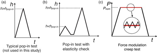
If confirmation of elastic behavior prior to pop-in is desired, a convenient method is to carry out small load and unload segments in the region of nominally elastic behavior. If only elastic deformation has occurred, the load and unload segment data will be identical when the load is plotted versus depth. Without checking to ensure that the loading is elastic, it is possible to still have a nominal 3/2 power law describing the load–depth relationship by assuming a slightly different tip radius, if there is a pop-in after this loading condition it would be common to assume that pop-in was indicative of the nucleation of dislocations. Typical load functions for pop-in tests with and without checks for elasticity are shown in (a) and (b), respectively. After performing many nanoindentation tests with checks for elastic behavior, we have noted that often there is some plasticity, or some phenomenon that mimics plasticity, occurring prior to pop-in. In the present work, we call this phenomenon of elastic-like loading followed by pop-in pseudo-Hertzian behavior.
Figure 1. Loading functions for QS and creep tests. (a) A typical test to determine pop-in load or depth. (b) The pop-in test with check for elasticity used in this study. (c) A force modulation technique creep test.
There is considerable evidence [Citation11,Citation12,Citation17–25] that, in the absence of dislocations, the transition from elastic to plastic behavior can be concurrent with pop-in; this leads to an implication that this defect-free condition is required for pop-in. Many of these works derive this conclusion from pristine sample volumes, dependencies that suggest nucleation, dislocation observation before and after pop-in, or simulations showing simultaneous load drop and dislocation multiplication.
There have, however, been reports of experimental evidence of plastic deformation prior to pop-in. Early suggestions in the literature assumed that plastic deformation prior to pop-in was attributed to phenomena such as the fracture of an oxide film.[Citation26] Elegant and convincing experimental evidence of dislocation activity prior to pop-in has been reported in the literature by Minor et al.,[Citation27] who conducted in situ nanoindentation tests inside a transmission electron microscopy. They found that volumes with considerable dislocation density could support shear stresses approaching the theoretical shear stress of the material. Kramer et al. detected a residual impression in the surface of electropolished single-crystal tungsten using an atomic force microscope at sub-critical loads immediately after load and hold experiments.[Citation28] The impression is reported to have disappeared after some time. Kiely et al. [Citation29] experimentally noted distinct changes in slope of the load–depth curve separate from and prior to pop-in during indentations in a pristine gold surface. Such ‘minor events’ could be from individual nucleation events, and left surface depressions from one to five atomic layers deep. In their tests, the fraction that displayed minor events decreased with increasing probe radius over a range of 400 nm to 2 µm, indicating that, for larger tip radii, individual nucleation events are more difficult to identify given the increasing load–to-maximum shear stress ratio for large indenters. In other studies, it has been found that the pop-in load is also inversely proportional to the dislocation density in the vicinity of the test.[Citation13,Citation25] This is discrepant with the notion that locally dislocation-free volumes are required for pop-in events, implying that all small volumes of material are not equivalent and that perhaps geometrical features such as dislocations are responsible. Further evidence of this is provided by Ma et al. [Citation30] who demonstrated the dependence of stress at pop-in on the size of the plastic zone by changing probe radius. This suggests that defects in the material are being sampled.
In addition to the experimental evidence of plasticity before pop-in, there have been recent simulations that show similar behavior. Engels et al. [Citation31] showed dislocation nucleation prior to softening in a perfect single crystal. Salehinia et al. [Citation32] investigated the transition from elastic to plastic behavior during nanoindentation with molecular dynamics. Their simulations, with vacancies in the vicinity of the indent, produce load–depth curves with jerky flow where the load–depth curve deviates erratically from the smooth loading curve, which is a characteristic of many simulations and experiments. The jerky flow correlates with the migration and eventual propagation of the vacancy to the surface. Only once dislocations are nucleated from the vacancy and propagated to the surface does a significant load drop reminiscent of pop-in occur. Further work by the same group [Citation33] used simulations and experiments to show that indentation near internal defects can lead to ‘sub-critical’ events (small perturbations in the smooth load–depth curve) and suggest ‘that the first event observed experimentally may not correspond to the first plastic deformation event’. Behavior like these sub-critical events and jerky flow curves has been observed by the authors in a variety of materials prior to a yield event.
Clearly, a discrepancy exists between the classical view of reversible indentation deformation and recent simulations and experimental work, warranting further investigation. If the apparent plasticity during the checks is a true representation of the material behavior and not due to machine drift or other equipment-related phenomena, then the plastic behavior is most likely the result of (1) plasticity due to mobile defects in the stressed volume, (2) surface asperities being flattened, or (3) deformation of a layer of surface contamination. It should be noted that case 2 would generate case 1 as described by Corcoran et al. [Citation9] Mobile dislocations in the stressed volume can be detected by the method of Asif and Pethica.[Citation34] Using the force modulation technique, they demonstrated room temperature indentation creep after pop-in. The pop-in is thought to be a dislocation nucleation or multiplication event, and consequently after this event, the small oscillating load combined with the static load is sufficient to further deform the material. In smooth samples they found no creep prior to pop-in.
It is impossible to know a priori whether any volume of material tested via nanoindentation contains defects such as mobile dislocations, or if the check for elasticity deforms or changes the material in some way. Such a change was described by Cross et al. [Citation35] where cyclic elastic loading produced ‘softening’, at the very earliest stages of contact. Here, additional compliance is evident, the extent of which scales with the amount of strain induced by the first indentation cycle. Because of these reasons, we take a statistical approach for determining if mobile dislocations are present in the small volumes probed by the indenter prior to pop-in. First, the general approach is described, then, further details of the tests and methods are presented. On each sample, depth-controlled quasi-static (QS) indentation tests with a check for elasticity were conducted ((b)). The statistical occurrence of apparent plasticity prior to pop-in was then compared to the occurrence of creeping creep tests at similar depths. For these experiments, we assume that the behavior of the material probed during the creep tests nominally describes the behavior of the material at different but adjacent positions in the sample where the QS tests were performed. That is, while the structure, properties, etc. may be different from point to point within a localized probe volume, one region of the bulk sample behaves the same as any other.
In each QS test, a check for elasticity was performed before a deeper indent by pressing the indenter into the material to a depth of 5 nm at a rate of 0.5 nm/s then retracting it to the zero depth. Next, in the same position on the sample, the indenter was pressed again into the material, but to a depth of 25 nm at a rate of 2.5 nm/s. The indenter was then retracted fully, completing the test. Using this loading scheme made it possible to determine if behavior suspected as plasticity was occurring before pop-in happened.
Twenty-five QS indents were performed in each sample. The frequency of the following three behaviors displayed by the QS tests was recorded: (1) truly elastic behavior during the elasticity check and prior to pop-in (we call this behavior elastic), (2) plastic behavior during the elasticity check with pop-in occurring during reloading (called pseudo-Hertzian), and (3) plastic behavior during the elasticity check, with gradual transition from elastic to plastic behavior when reloaded (plastic).
Samples of four materials with varying crystal structures were tested, cobalt (HCP), iridium (FCC), platinum (FCC), and tungsten (BCC). All materials were ‘commercially pure’, and above 99% purity. The polycrystalline cobalt and the (1 0 0) single-crystal iridium were mechanically polished through 0.05 µm alumina, annealed to reduce the dislocation density enough to produce pop-ins, then indented. These two samples were annealed at 40% of their melting temperature in an Ar-95% H-5% atmosphere, this, coupled with their inherent oxidation resistance, prevented significant oxides from forming on their surfaces. The polycrystalline platinum was tested directly after mechanical polishing and the tungsten sample used was an electropolished (1 0 0) single crystal. The average roughness of the Co sample was less than 10 nm as determined by a atomic force microscope using a 10-µm square scan. The other mechanically polished samples should have a similar roughness. The electropolished tungsten should be significantly smoother.
QS nanoindentation tests can be susceptible to the thermal drift of the depth measurement. This is problematic for tests covering long periods of time. The force modulation technique, first applied to creep tests by Asif and Pethica,[Citation34] eliminates this shortcoming by measuring the contact stiffness continuously throughout the test. In such tests, load-control is used to apply a prescribed nominal load between the indenter and the sample. A smaller oscillating force is then superimposed upon the nominal load, which causes the indenter displacement to oscillate while continuously maintaining contact with the sample. In this way, the stiffness during each oscillation is measured and a continuous measurement can be made. An increase in the contact stiffness indicates an increase in the penetration depth, and for these tests with a constant nominal load, increases in the contact stiffness also indicate indentation creep. For this reason, the force modulation technique in the manner of [Citation34] was used for the creep tests. Thirty-six creep tests ((c)) were performed in each sample at each of two loads for 100 s. These creep tests were sorted into either creeping or not-creeping behavior. If the contact stiffness changed more than 10% from its initial value, then that test was identified as one that was creeping. Two nominal loads between 10 and 40 µN were chosen for each sample. The larger of the two loads for the Co, Ir, and Pt samples was chosen as the approximate maximum load developed during the initial loading segment of the most compliant QS test in the respective material. The second load was set at half of the first value. Choosing the creep test load in this manner ensures that the creep tests were performed at about the same, or slightly below the amount of deformation induced by the QS test during the check for elasticity. The same loads used on the Ir sample were applied to the W sample because of its similar stiffness and because it was known that the W sample reliably displayed elastic behavior prior to pop-in. The load amplitude was chosen to be as small as possible but maintain a displacement amplitude typical of force modulation method tests found in the literature. The load amplitude for all creep tests was 7 µN. This resulted in a displacement amplitude typically between 0.6 nm and 0.8 nm, depending on the stiffness of the sample. The oscillation frequency was 220 Hz. The loading function used for the creep tests is shown in (c). Some tests were performed with a short 5-s hold period at the start of the creep tests at the same nominal load but with the load amplitude reduced by 25%. This was to check for effects of changing the load amplitude.
Both the QS and creep tests were performed with a Hysitron Triboindenter (Eden Prairie, MN), using a Berkovich tip with a radius of 200 nm. As is typical, the radius was determined by fitting the contact approximation proposed by Hertz [Citation16] to the load–depth curves of elastic indentation data. Seven randomly chosen elastic QS indents in the tungsten sample were used for this purpose.
To test the effect of surface contamination, 10 QS and 10 creep tests were conducted on a 370×490-µm region of the tungsten sample after it was scanned in a Phillips/FEI XL40 scanning electron microscope (SEM) (FEI Company, Hillsboro, OR) for approximately 35 min. The electron beam contaminates the sample by depositing a thin carbonaceous layer.[Citation36] Assuming the carbon layer to be more compliant than the metal substrates, any effect on the layer would be most easily detectable via creep tests on the tungsten sample because of its smooth surface and high stiffness. This test also replicates the case where indenter tips are imaged in an SEM then immediately put into service.
Upon completion of the tests, it was found that all the samples demonstrated a range of behaviors. A typical curve of each type of behavior from QS tests in Ir is shown in . The tungsten sample demonstrated the greatest number of indents where the material displayed elastic behavior from the QS tests with only one falling into the pseudo-Hertzian category. The platinum displayed no elastic behavior though there were multiple pop-ins throughout all of the tests. The other two samples displayed all three types of behavior. This is summarized in .
Figure 2. Typical QS curves from tests in Ir showing (1) completely elastic behavior prior to pop-in, (2) pseudo-Hertzian behavior prior to pop-in, and (3) gradual elastic-to-plastic transition with no pop-in (pseudo-Hertzian and plastic curves are depth offset for clarity).
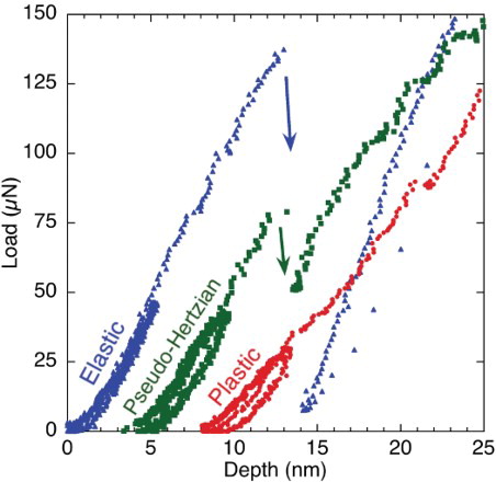
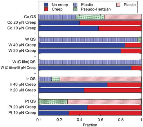
Figure 3. Relative fractions of material behavior from QS tests and creep tests.
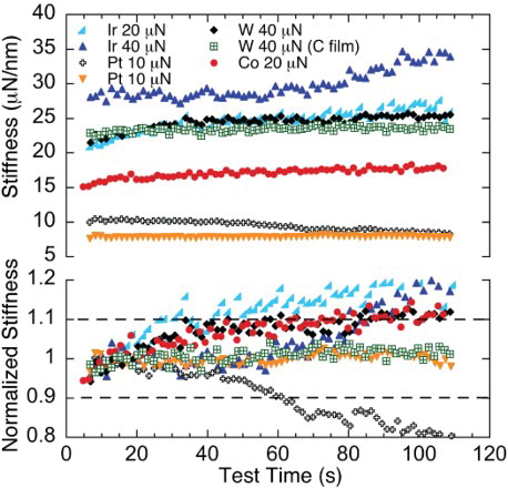
The contact stiffness during the creep tests typically increased or remained constant. Typical contact stiffness (S) versus time curves are shown in . There were some tests, particularly in Pt at the lowest loads, where the stiffness decreased during the hold. These decreasing stiffness tests are evidence of mobile dislocations, and so are binned with the creeping indents. summarizes the incidence of creeping and not-creeping material behavior as a fraction of the total number of tests. To normalize the stiffness for easier identification of creeping behavior, the initial stiffness, S0, which is the average stiffness over the first 12.5 s of the test, was first determined. If the instantaneous value of the stiffness became more than 10% different from the initial value, the material was said to be creeping. also shows the value of the normalized stiffness (S/S0) for some typical curves. The previously mentioned change in load amplitude did not influence the trend of the material behavior.
Figure 4. Typical contact stiffness and normalized stiffness versus time curves from the reference creep tests.
When comparing the tungsten sample after possible contamination by the SEM, the contact stiffness was in the same range as before. If a carbonaceous contamination layer influenced the sample behavior, it would be detectable by reduced contact stiffness since the tip would be measuring the properties of the layer. Figure shows that the percentage of tests displaying each material behavior is generally the same between samples imaged in the SEM and as-prepared pristine samples. In light of this, it appears that contamination by deposition of carbon in an SEM prior to indentation does not appreciably alter the apparent material behavior at tests to extremely shallow depths.
Having ruled out surface contamination as a factor in these experiments, we turn our discussion to creep behavior. Asif and Pethica [Citation34] demonstrated that creeping occurred in mechanically polished tungsten with ‘a 0.25-µm finish’, but that pop-in did not. However, in electropolished samples, no creeping occurred until after a pop-in event. They attribute this difference to the significant mobile dislocation content generated by the mechanical polishing. With loads around 1 mN, their study used significantly higher loads than ours. Because of this, the contact radius should be much larger, and a larger zone of high stresses and/or plastic behavior would exist when compared to our creep tests in W. For greater loads, and thus larger volumes with significant stresses, a smoother surface with larger regions devoid of dislocations would be required to prevent creep. The behavior of the materials in our study suggests that when the material is brought to a finer surface finish, even if by mechanical means, the dislocation structure below the surface is such that there are large enough regions devoid of dislocations that they are not moved during nominally elastic regime stresses at small indentation loads, that is, the traditional pop-in phenomenon still occurs. This is demonstrated by the elastic and non-creeping behaviors that occur at shallow depths.
In the case of the plastic QS indents, it is believed that significant dislocation content exists in localized regions. Indents that happen to be performed in these regions encounter material that accommodates significant general plasticity and no pop-in occurs. Material with this local structure would also display significant plastic deformation when tested for creep.
Now, comparing the QS tests to the creep tests, it is found that the sum of the frequencies of QS tests displaying plastic and pseudo-Hertzian behavior compares similarly to the frequency of the creeping behavior from the creep tests in all cases except for the Ir. The behavior of the Ir could be the result of the two loads used in these creep tests being too low to adequately represent the plastic zone developed by the QS test. This is likely since Ir is stiffer than the other samples yet similar loads were used. The similar frequency of these behaviors from the two different types of tests shows that the apparent plastic behavior prior to pop-in is the result of mobile dislocations. This can be explained as follows. When the material behavior is pseudo-Hertzian, there are mobile dislocation lines, but initially the stress field is spatially insufficient to engulf a significant source for multiplication at a stress level needed to activate that source. As the indenter penetrates deeper into the material, these existing dislocations move to accommodate some plasticity until they are pinned or their motion is otherwise impeded, only when the stress at these trapped dislocations reaches a critical level or do the stresses grow great enough to activate some other source further from the tip will pop-in occur. This is consistent with the findings of [Citation27] as described earlier.
Two other features of should be discussed. First, the Pt sample displayed no truly elastic QS tests, yet the corresponding behavior in the creep test, not-creeping behavior, is present. In our determination of the behavior of individual creep tests, we strictly adhered to the 10% change criterion that was established. Had some of these tests, particularly in the Pt and Ir samples, continued they would likely have crossed the 10% threshold (see ), been counted as creeping, and thus reduced the number of ‘not-creeping’ tests. A longer creep test time would then provide better correlation between the percentage of tests displaying not-creeping and truly elastic behaviors, or conversely, between the creeping tests and the other two QS behaviors. However, in an effort to make this process amenable to statistical testing, we selected a time of test and an arbitrary ‘10%’ value that we felt would be adoptable within conventional testing methodologies.
The other feature of which bears further examination is the fact that, in most cases, the creep tests carried out at a lower load exhibit more creep than those at the higher load condition. This is likely an artifact due to the normalization procedure and our definition of ‘creeping’ as a change in stiffness of 10%. Take for example, the tests in Ir shown in . Here, the magnitude of the change in stiffness is in most cases about the same, for both the larger and the smaller of the two loads. This change, as a percentage of the initial load, is greater for the smaller load, therefore, when normalizing it is easier to exceed the ‘10% rule’ that was chosen. A more refined definition of creep at very low loads may be needed in the future to explore a broader range of mechanisms using quantitative, statistically based assessments of nanoindentation behavior.
In light of these findings, it is suggested that for studies on incipient plasticity, a hybrid method of determining the elastic versus the plastic nature of contacts would provide a more robust way to identify the nature of the deformation. In such a hybrid method, the force modulation technique should be performed for an appropriate amount of time at a sub-critical load until the nature of the contact is determined, then the test can be continued on the same volume of material using the QS method for detection of the pop-in event.
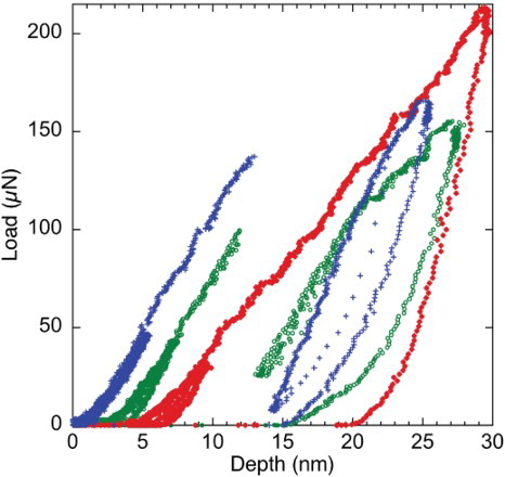
In a final observation, we note that there appears to be an inverse relationship between the pop-in load and the amount of plastic behavior during the initial load/unload portion in the QS tests. The load at pop-in decreases when there is more-plastic behavior, as can be seen in . If the plastic behavior is the result of dislocations, then our results are consistent with the inverse relationship between first pop-in load and dislocation density as previously mentioned. Further, it is clear from the inspection of the data that while generally the material behavior can be classified into elastic, pseudo-Hertzian, or plastic, the material does display a spectrum of behaviors between the extremes of purely elastic and plastic. This is due to the probability of indenting material with the appropriate microstructural or surface features for each type of behavior.
Figure 5. Load–depth curves in cobalt, displaying a weak trend between pop-in load and degree of plasticity recorded prior to pop-in (the two more-plastic curves are depth offset for clarity).
Since flattening of surface asperities will contribute to the dislocation content in a thin region of the material near the indenter tip, pop-in behavior should be influenced by surface roughness. Wang et al. demonstrated this by indenting single-crystal Mo with different surface finishes.[Citation37] It is likely that surface asperities on the Co, Pt, and Ir samples generate mobile dislocations near the surface of the sample when indented. It seems logical that these dislocations contribute to both the creep and the plastic QS indent behavior. Additionally, since the pseudo-Hertzian behavior tracks with the creep behavior it seems that these asperity-generated dislocations contribute when there is plasticity prior to pop-in as well. The conclusion of this current study is that it is now clearly evident that in a wide range of metallic materials pop-ins will occur despite mobile dislocations in the sampled volume. Studies of incipient plasticity must be conducted with checks for elasticity at each location for the results to be considered the true elastic-plastic transition. If such studies are compared to simulations suggesting design approaches for ultra-strong defect-free volumes this statistically accessible testing methodology provides a viable method for direct comparison in assessing ‘theoretical strength’ in what may have been considered a defect-free volume.
Acknowledgements
The authors would like to thank Samantha K. Lawrence for the surface roughness measurement of the Co, and for the financial support of the National Science Foundation's CMMI program under grant #1030843.
References
- Brenner SS. Tensile strength of whiskers. J Appl Phys. 1956;27(12):1484. doi: 10.1063/1.1722294
- Bei H, Shim S, Pharr GM, George EP. Effects of pre-strain on the compressive stress–strain response of Mo-alloy single-crystal micropillars. Acta Mater. 2008;56(17):4762–4770. doi: 10.1016/j.actamat.2008.05.030
- Ng KS, Ngan AHW. Stochastic nature of plasticity of aluminum micro-pillars. Acta Mater. 2008;56(8):1712–1720. doi: 10.1016/j.actamat.2007.12.016
- Gane N. Microdeformation of solids. J Appl Phys. 1968;39(3):1432. doi: 10.1063/1.1656376
- Page TF, Oliver WC, McHargue CJ. The deformation behavior of ceramic crystals subjected to very low load (nano)indentations. J Mater Res. 1992;7(02):450–473. doi: 10.1557/JMR.1992.0450
- Spary IJ, Bushby AJ, Jennett NM. On the indentation size effect in spherical indentation. Philos Mag. 2006;86(33–35):5581–5593. doi: 10.1080/14786430600854988
- Lowry MB, Kiener D, LeBlanc MM, Chisholm C, Florando JN, Morris JW, Minor AM. Achieving the ideal strength in annealed molybdenum nanopillars. Acta Mater. 2010;58(15):5160–5167. doi: 10.1016/j.actamat.2010.05.052
- Oliver WC, Pharr GM. An improved technique for determining hardness and elastic modulus using load and displacement sensing indentation experiments. J Mater Res. 1992;7(6):1564–1583. doi: 10.1557/JMR.1992.1564
- Corcoran SG, Colton RJ, Lilleodden ET, Gerberich WW. Anomalous plastic deformation at surfaces: nanoindentation of gold single crystals. Phys Rev B. 1997;55(24):R16057. doi: 10.1103/PhysRevB.55.R16057
- Bahr DF, Kramer DE, Gerberich WW. Non-linear deformation mechanisms during nanoindentation. Acta Mater. 1998;46(10):3605–3617. doi: 10.1016/S1359-6454(98)00024-X
- Schuh CA, Mason JK, Lund AC. Quantitative insight into dislocation nucleation from high-temperature nanoindentation experiments. Nat Mater. 2005;4(8):617–621. doi: 10.1038/nmat1429
- Tromas C, Gaillard Y, Woirgard J. Nucleation of dislocations during nanoindentation in MgO. Philos Mag. 2006;86(33–35):5595–5606. doi: 10.1080/14786430600690499
- Zbib AA, Bahr DF. Dislocation nucleation and source activation during nanoindentation yield points. Metall Mater Trans A. 2007;38(13):2249–2255. doi: 10.1007/s11661-007-9284-5
- Dietiker M, Nyilas RD, Solenthaler C, Spolenak R. Nanoindentation of single-crystalline gold thin films: correlating hardness and the onset of plasticity. Acta Mater. 2008;56(15):3887–3899. doi: 10.1016/j.actamat.2008.04.032
- Lawrence SK, Bahr DF, Zbib HM. Crystallographic orientation and indenter radius effects on the onset of plasticity during nanoindentation. J Mater Res. 2012;27(24):3058–3065. doi: 10.1557/jmr.2012.368
- Hertz H. Miscellaneous papers. New York: MacMillan; 1896. p. 163–183.
- Gerberich WW, Venkataraman SK, Huang H, Harvey SE, Kohlstedt DL. The injection of plasticity by millinewton contacts. Acta Metall Mater. 1995;43(4):1569–1576. doi: 10.1016/0956-7151(94)00351-H
- Mann AB, Pethica JB. The role of atomic size asperities in the mechanical deformation of nanocontacts. Appl Phys Lett. 1996;69(7):907. doi: 10.1063/1.116939
- Biener MM, Biener J, Hodge AM, Hamza AV. Dislocation nucleation in bcc Ta single crystals studied by nanoindentation. Phys Rev B. 2007;76(16):165422. doi: 10.1103/PhysRevB.76.165422
- Li J, Van Vliet KJ, Zhu T, Yip S, Suresh S. Atomistic mechanisms governing elastic limit and incipient plasticity in crystals. Nature. 2002;418(6895):307–310. doi: 10.1038/nature00865
- Montagne A, Audurier V, Tromas C. Influence of pre-existing dislocations on the pop-in phenomenon during nanoindentation in MgO. Acta Mater. 2013;61(13):4778–4786. doi: 10.1016/j.actamat.2013.05.004
- Lorenz D, Zeckzer A, Hilpert U, Grau P, Johansen H, Leipner HS. Pop-in effect as homogeneous nucleation of dislocations during nanoindentation. Phys Rev B. 2003; 67(17):172101. doi: 10.1103/PhysRevB.67.172101
- Bahr DF, Vasquez G. Effect of solid solution impurities on dislocation nucleation during nanoindentation. J Mater Res. 2005;20(08):1947–1951. doi: 10.1557/JMR.2005.0244
- Gerberich WW, Nelson JC, Lilleodden ET, Anderson P, Wyrobek JT. Indentation induced dislocation nucleation: the initial yield point. Acta Mater. 1996;44(9):3585–3598. doi: 10.1016/1359-6454(96)00010-9
- Lodes MA, Hartmaier A, Göken M, Durst K. Influence of dislocation density on the pop-in behavior and indentation size effect in CaF2 single crystals: experiments and molecular dynamics simulations. Acta Mater. 2011 Jun;59(11):4264–4273. doi: 10.1016/j.actamat.2011.03.050
- Venkataraman SK, Kohlstedt DL, Gerberich WW. Continuous microindentation of passivating surfaces. J Mater Res. 1993;8(4):685–688. doi: 10.1557/JMR.1993.0685
- Minor AM, Syed Asif SA, Shan Z, Stach EA, Cyrankowski E, Wyrobek TJ, Warren OL. A new view of the onset of plasticity during the nanoindentation of aluminium. Nat Mater. 2006;5(9):697–702. doi: 10.1038/nmat1714
- Kramer DE, Yoder KB, Gerberich WW. Surface constrained plasticity: oxide rupture and the yield point process. Philos Mag A. 2001;81(8):2033–2058. doi: 10.1080/01418610108216651
- Kiely JD, Jarausch KF, Houston JE, Russell PE. Initial stages of yield in nanoindentation. J Mater Res. 1999;14(6):2219–2227. doi: 10.1557/JMR.1999.0298
- Ma L, Morris DJ, Jennerjohn SL, Bahr DF, Levine LE. The role of probe shape on the initiation of metal plasticity in nanoindentation. Acta Mater. 2012;60(12):4729–4739. doi: 10.1016/j.actamat.2012.05.026
- Engels P, Ma A, Hartmaier A. Continuum simulation of the evolution of dislocation densities during nanoindentation. Int J Plast. 2012;38:159–169. doi: 10.1016/j.ijplas.2012.05.010
- Salehinia I, Perez V, Bahr DF. Effect of vacancies on incipient plasticity during contact loading. Philos Mag. 2012;92(5):550–570. doi: 10.1080/14786435.2011.628635
- Salehinia I, Lawrence SK, Bahr DF. The effect of crystal orientation on the stochastic behavior of dislocation nucleation and multiplication during nanoindentation. Acta Mater. 2013;61(5):1421–1431. doi: 10.1016/j.actamat.2012.11.019
- Syed Asif SA, Pethica JB. Nanoindentation creep of single-crystal tungsten and gallium arsenide. Philos Mag A. 1997;76(6):1105–1118. doi: 10.1080/01418619708214217
- Cross GLW, Schirmeisen A, Grütter P, Dürig UT. Plasticity, healing and shakedown in sharp-asperity nanoindentation. Nat Mater. 2006;5(5):370–376. doi: 10.1038/nmat1632
- Randolph SJ, Fowlkes JD, Rack PD. Focused, nanoscale electron-beam-induced deposition and etching. Crit Rev Solid State Mater Sci. 2006;31(3):55–89. doi: 10.1080/10408430600930438
- Wang Z, Bei H, George EP, Pharr GM. Influences of surface preparation on nanoindentation pop-in in single-crystal Mo. Scripta Mater. 2011;65(6):469–472. doi: 10.1016/j.scriptamat.2011.05.030