
Abstract
Understanding radiation effects on the mechanical properties of SiC composites is important to their application in advanced reactor designs. By means of molecular dynamics simulations, we found that due to strong interface bonding between the graphene layers and SiC, the sliding friction of SiC fibers is largely determined by the frictional behavior between graphene layers. Upon sliding, carbon displacements between graphene layers can act as seed atoms to induce the formation of single carbon atomic chains (SCACs) by pulling carbon atoms from the neighboring graphene planes. The formation, growth, and breaking of SCACs determine the frictional response to irradiation.
1. Introduction
SiC composites are an important enabling material for components of future advanced reactor systems because they are both chemically and neutronically inert and retain physical properties at high temperature (>1600°C).[Citation1,Citation2] Nuclear applications for SiC composites include light water reactor (LWR) fuel cladding, fast reactor fuel cladding, and advanced high temperature reactor (AHTR) fuel clad.[Citation3,Citation4] SiC composites can potentially facilitate higher burn up levels in future nuclear reactors enhancing their reliability and economic competitiveness. The need to develop SiC-based cladding or other suitable alternatives is urgent considering past accidents at Fukushima, and Three Mile Island. Both accidents resulted from loss of coolant and subsequent chemical reaction of zircaloy fuel cladding, which produced explosive hydrogen. Steam reaction rates with SiC are ∼50–100 times lower than zircaloy at high temperature.[Citation5,Citation6] In general, high thermal stability, reduced oxidation reaction, and reduced hydrogen generation make SiC attractive as fuel cladding materials of enhanced accident tolerance. But, as a ceramic, SiC is brittle and its ductility needs to be improved.
Among various SiC composites, fiber-strengthened SiC composites have gained a great interest because of their superior mechanical strength. The benefit comes from the fact that fibers can easily slip under loading, thus providing a way for stress energy release and for improving ductility.[Citation7] The almost friction-free slip is realized by adding a layer of graphitic materials, such as pyro-carbon, as lubricant between the SiC fibers and the SiC matrix. In the fabrication process, such composites are fabricated via chemical vapor infiltration, a process in which reactant gases diffuse into an isothermal porous preform of long continuous fibers and form a deposit.[Citation8]
To the best of our knowledge, no studies have addressed the effect of radiation damage on the frictional behavior of SiC composites via an atomistic approach. If the friction-free property is lost upon irradiation, a transition toward fragile nature of bulk materials is expected. This complexity calls for the need of fundamental studies to obtain atomic-scale understanding. By means of molecular dynamics (MD) simulations, the present study is aimed to understand the fundamental frictional behavior of SiC fibers in composites. The study is not indented to build a linkage to neutron damage due to both time and length scale limits.
2. Methodology
In the present work, we studied the atomic-scale frictional behavior of two graphene sliding systems with preloaded C displacements. The first systems are few-layer graphene sandwiched between two SiC substrates. The second system is composed of two graphene sheets, representing an ideal system to reveal the fundamental physics. As to be discussed, the physical mechanism behind the frictional behavior seen in the SiC/graphene/SiC composite is revealed in the bilayer graphene system.
MD simulations were performed using the Large-scale Atomic/Molecular Massively Parallel Simulator code.[Citation9] Our model system is a sandwich-like structure with few-layer graphene buried between two SiC layers. The adaptive intermolecular reactive bond order (AIREBO) potential was used to describe carbon interactions in graphene layers.[Citation10] The AIREBO potential has been widely used to describe carbon systems because of the good agreement between modeling prediction and experimental observation.[Citation10] The Tersoff potential with a short-range pairwise interaction smoothly linked to the Ziegler–Biersack–Littmark potential is used to describe atomic interactions within the SiC layers, and the SiC/graphene interfacial regions.[Citation11,Citation12] These potentials led to an interplanar spacing in graphite of 3.4 Å, which was selected based on experimental measurements in graphite.[Citation13]
The SiC/graphene/SiC composite and the bilayer graphene were self-irradiated by 300 eV carbon atoms at random positions with an incident angle ranging from 7° to 11° away from the normal to the graphene planes to avoid ion channeling effects. The selection of 300 eV considers the need to confine the damage to the region of the interest and the fact that damage cascades are created at low energies (C irradiation in SiC reaches its peak nuclear stopping power at an energy of a few keVs). The system consisted of 17 Å of 3C-SiC on the top, 4 layers of graphene in the middle, and 10 Å of SiC on the bottom. The length and width of the system were 86 Å × 124 Å, which were much larger than a typical damage cascade created from 300 eV C atom bombardments. The created damage was allowed to evolve toward the formation of stable defects. In the composite model, radiation and cooling process are repeated up to 75 times to increase the damage levels, whereas only single C irradiations were performed in the bilayer graphene system. The frictional force was determined by horizontally moving the top SiC(graphene) layer with a constant speed of 1 Å/ps (0.25 Å/ps) in the composite (bilayer graphene). The structures were relaxed at 300 K under NVT ensemble (fixed particle number N, volume V, and temperature T) before and after collisions, while the collision process used an NVE ensemble (fixed particle number N, volume V, and energy E). The sliding process used the NVE ensemble and the sliding temperature was kept at 300 K by rescaling the velocities every 100 time step. The modeling time step was 0.1 fs for the collision process and relaxation and 1 fs for the sliding process.
3. Results and discussion
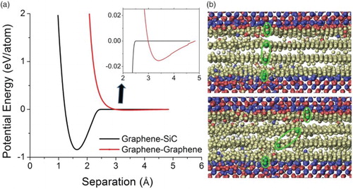
In order to answer the question of how friction forces are distributed across the composite, the interaction strength between SiC and graphene, and between graphene layers is computed. (a) compares the per atom potential energy change for interaction between an SiC/graphene system and a graphene/graphene system. For the SiC/graphene interface, the energy shows a deep dip of ∼0.7 eV per atom at an equilibrium separation distance of 1.65 Å. In comparison, the graphene–graphene interplanar interaction is much weaker since the interaction here is dominated by the weak Van der Waals force, resulting in a dip that is barely noticeable in (a). As shown by the inset, the energy dip is less than 0.02 eV per atom and the equilibrium separation distance is about 3.4 Å. This distance agrees well with the experimental results.[Citation13] The significant difference in interaction strengths leads to sliding exclusively between graphene layers with very little slip occurring between the graphene and SiC. In other words, frictional contributions from the SiC/graphene interfaces are negligible in comparison to that from the graphene–graphene sliding. This difference is clearly observed in (b). In contrast to the top and bottom SiC/graphene interfaces, the two graphene planes in the central region show a large relative displacement between one another.
Figure 1. (color online) (a) Interaction energy changes of graphene–SiC and graphene–graphene systems as a function of separation distance and (b) atom positions of SiC/graphene/SiC composite before (top) and after sliding (bottom).
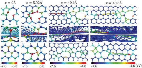
Since the frictional behavior of SiC/graphene composites is dominated by interactions between graphene planes, we now focus on atomic-scale details of gliding between two graphene planes. shows the atomic-scale structural evolution of a bilayer system upon sliding. At zero displacement, one carbon interstitial is introduced between the planes. The interstitial reaches a stable configuration by forming sp3 bond with the lower graphene plane and sp2 bond with the top graphene plane. This configuration presents one likely scenario upon energy minimization, as reported by previous studies.[Citation14,Citation15] Upon displacement to 5.02 Å, instead of the bond breaking, the interstitial begins to pull out a chain of atoms from the planes, leading to cavity formation on both planes and a 6 atom single carbon atomic chain (SCAC). The pulled carbon atoms along the one-dimensional chain form sp bonds with their immediate neighbors. Only those atoms close to both chain ends have bonds with the neighboring graphene planes. Upon displacement to 40.4 Å, the SCAC is 14 atoms long. The angle between the chain and the graphene plane is small enough (∼10°) that some chain atoms begin to form sp2/sp3 bonds with the planes, depending on their vicinity to the plane atoms. Upon further displacement to 40.6 Å, the pulling process stops and the increased chain interactions with graphene planes create a large stress on the chain, leading to the chain breaking in the middle. The broken chains will not remain straight. Upon relaxation, they become curved or self-entangled.
Figure 2. (color online) The formation of an SCAC upon sliding a bilayer graphene layer system as a function of horizontal displacements. The color represents the atoms’ potential energies. One carbon displacement is initially loaded between the graphene planes.
The bond breaking and reformation process sensitively affects the system energy, and thus the friction force upon sliding. links the microscopic potential energy change and atomic-scale rearrangement upon SCAC formation. The potential energy change is extracted from a region within a 50 Å radius from the initial displacement. As shown in (a), the energy rises to a saturated value with increasing sliding displacement. The potential energy change is superimposed with periodic spike-like features. (b) represents a single spike from the boxed region. (c) shows snapshots of MD simulations corresponding to the three arrows indicated in (b). At position ‘1’, the potential energy reaches the peak of the spike. This corresponds to the maximum distortion associated with the atom pulling due to accumulated stress energy from pulling. However, the structure can release energy through atomic rearrangement of the cavity. This rearrangement is more difficult when the cavity size is small. Thus, the potential energy increases with cavity size for short displacements (≤20 Å). Once the cavity reaches a certain size, the potential energy trend becomes saturated.
Figure 3. (color online) (a) Potential energy as a function of sliding displacements for an interstitial-loaded bilayer graphene system, (b) enlarged plot of the box marked region, and (c) atomic configurations corresponding to three marked positions in (b).
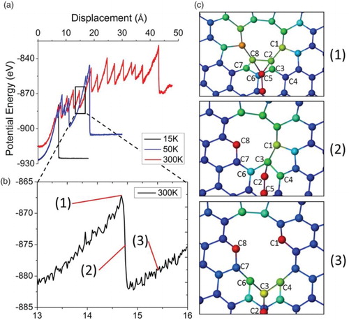
(c) clearly reveals the atomic-scale details of the pulling and relaxation process. At position ‘1’, the atoms marked as C2 and C8 form sp3 bond with the chain end atom (C5) and other surrounding graphene atoms. For the next step, either C2 or C8 will be pulled out. At position ‘2’, C2 breaks the bond with C8 and joins the chain as the newest atom at the end of the chain. This process is immediately followed by rebonding of C1 and C3 along the cavity edge. Next, C3 is debonded from C1 and joins the chain. At position ‘3’, the bond configurations among C6, C4, and C3 resemble the structures at position ‘1’. A similar debonding process follows with further pulling, causing the cavity size to increase. This process will repeat until the chain breaks. The chain breaking leads to the last spike drop shown in (a).
At room temperature with a slow sliding speed, the sliding induced temperature rise is believed to be small. Therefore, the work done is almost fully converted to stress energy. The repeating spike pattern is a result of the small sampling size. For much larger systems, there will be more chains contributing to the frictional force, resulting in a smooth curve. At higher temperatures, both pulling and debonding will be relatively easier due to the reduced threshold energy for bond breaking. The thermal vibration is expected to assist both debonding at the chain ends and bonding to the graphite planes along the mid-section of the chain. Further complexity arises when the enhanced interactions between chain atoms with the graphene planes due to thermal vibrations are considered and when the chain angle with the graphene plane becomes small. The low energy required to pull a chain and the increased likelihood for chain–graphene interactions represent two competing mechanisms to determine the maximum SCAC length, since the former will increase the chain length, but the latter will decrease the chain length.
The present study reports, for the first time, SCAC formation between sliding graphene planes. SCACs were first discovered in trace amounts in nature around 1968.[Citation16] Since then, a wealth of research has been devoted to understanding mechanical and electrical properties of SCACs.[Citation17–19] While it is highly debatable whether this material can exist in bulk, individual SCACs have been experimentally created by numerous methods including gas-phase deposition, epitaxial growth, electrochemical synthesis, and thinning of carbon nanoribbons.[Citation20–27] Recent experimental studies have shown SCAC formation under transmission electron microscopy (TEM). Hobi et al. observed an individual SCAC formation by bombarding graphene nanoribbons by electrons. Electron irradiation displaces atoms narrowing down the ribbon width, eventually thinning the ribbon into a SCAC.[Citation25] In another experimental and modeling integrated study, Borrnert et al. shows the SCAC formation upon coalescence of fullerenes filled in a single-wall carbon nanotube (CNT).[Citation27] Similar SCAC formation has been predicted by modeling in other carbon systems.[Citation28–30] Wang et al. showed SCAC formation between the edges of two incrementally separated graphene islands using classical MD and the Car–Parinello MD method.[Citation30] Furthermore, Wang found that the formation process was statistical in nature and strongly dependent on the temperature of the system. In another modeling study, Castelli et al. shows SCAC formation in nanoholes formed in graphene via density functional theory modeling.[Citation30]
In order to understand the role of SCACs in determining the macroscopic frictional behavior, we now return to the SiC/graphene/SiC composite system. The mechanical properties of the irradiated composite are studied by changing the number of bombarding carbon atoms. compares the shear force vs. sliding displacements at different damage levels. For an unirradiated composite, (a) shows a relatively flat curve, which is determined solely by Van der Waals interactions. After a bombardment by 25 carbon atoms, the shear force increases and reaches its peak value at about 15 Å, then decreases slightly to a saturated value. By increasing the number of bombarding atoms to 50 and 75, (c) and 4(d) show that the maximum shear forces are further increased. Furthermore, the slopes before reaching the maximum also increase with increasing damage levels. Examination shows that the peak force occurs at about 15 Å which corresponds to the critical sliding distance at which SCACs start to break. However, a fraction of SCACs can survive at much longer sliding distances. Beyond the peaks, the shear forces decrease and expose a tail, toward a saturated value still above the value of the unirradiated composite. The enhancement seen in the saturated region is caused by the breaking of SCACs of longer surviving lengths as well as reattachment of broken SCACs. This variability in SCAC lifetime, as well as the reattachment of broken SCACs contributes to the gradual decline in force seen after the peak.
Figure 4. The averaged force per unit area required for sliding at a constant speed of 1 Å/ps, for SiC/graphene/SiC composite (a) unirradiated and irradiated by (b) 25, (c) 50, and (d) 75 carbon atoms of 300 eV.

Results in can easily be converted to typical shear stress vs. strain curves, showing that the irradiated composite will have irradiation enhanced shear modulus and shear strength. However, there are several distinctive features when compared to bulk materials. First, although irradiation enhanced shear strength is generally observed in bulk materials, irradiation is not expected to change the shear modulus since this intrinsic property is determined by the bonding nature, which does not change in bulk materials as a result of irradiation. However, in irradiated graphene systems, the formation of SCACs indeed changes the bonding nature, from Van der Waals forces in defect-free graphene to a mixture of Van der Waals force from undamaged regions and covalent bonding from SCACs. Second, in bulk materials, dimension changes caused by stress lower than the shear strength are reversible. However, in defective graphene systems, SCACs will not disappear once they form since the chain atoms are unable to refill the formed cavities. Third, in graphene systems irradiated to ultra-high damage levels, frictional behaviors are further complicated due to competing effects from SCACs and associated cavity formation. SCACs will increase interplanar roughness and promote the mid-chain bond formation between SCACs and graphene atoms, leading to enhanced frictional forces, while cavity formation will reduce the areas governed by Van der Waals interactions. SCAC reattachment to other SCACs and cavities was observed in this study. Fourth, in a cyclic force loading process, the previously formed unbroken and untangled SCACs have a small contribution to the frictional force at the beginning of sliding, but sudden frictional force rises are expected when the sliding stretches the SCACs, which is different from the traditional stress–strain behaviors seen in deformation/cold-work hardened bulk materials.
Experimental verification of the modeling prediction is challenging. One possible way is to study the frictional behaviors of an SiC fiber in SiC composites by applying either a continuous or repeated force loading. Radiation damage can be introduced by using ion irradiation. To alleviate the issue that ion irradiation creates damage zones of limited depths, the unirradiated regions need to be separated from the irradiate region. This might be achievable by using a focused ion beam technique to make a trench to isolate the surface irradiated region. The required forces to pull one SiC fiber out of the matrix,, and the force changes as a function of radiation damage levels, can be used to compare with the modeling prediction from the present study.
4. Conclusion
We have modeled the frictional interactions introduced by irradiation in SiC/graphene/SiC and bilayer graphene structures. The bilayer graphene simulations revealed that an interplanar defect created in graphene could result in the formation of an SCAC. As the graphene layers are further displaced, the SCAC breaks into two isolated chain each anchored to its respective graphene sheet. The formation and breaking of SCACs is shown to dominate the frictional response in the SiC/graphene/SiC composite. The shear modulus measured in the composite is determined by the SCAC density. Furthermore, the breaking of SCACs and debonding seen in the composite system points to a possible mechanism for debonding observed in SiC fiber composite systems.
Further work is required to fully understand the role of friction in the irradiated SiC/graphene-based composite and determine the suitability of the fiber-strengthened SiC composite as reactor core component materials. First of all, the enhanced shear modulus and frictional forces will inhibit the pulling out process, which decreases the capability of the matrix to release stress energy. Second, pulling in after pushing out an SiC fiber causes SCACs or broken SCACs to curve or entangle making the mechanical properties irreversible. Furthermore, SCAC formation is promoted by environments which combine irradiation effects with stress/sliding. Therefore, stress/sliding participates in damage creation and enhances cavity formation. SCACs and interplanar defect clustering resulting from structural relaxation of broken SCACs will speed up the structural collapses leading to lower amorphization tolerance. These unique radiation effects must be appropriately considered in the materials screening process.
Disclosure statement
No potential conflict of interest was reported by the authors.
Additional information
Funding
References
- Katoh Y, Snead LL, Henager CH Jr., et al. Current status and critical issues for development of SiC composites for fusion applications. J Nucl Mater. 2007;367–370:659–671. doi: 10.1016/j.jnucmat.2007.03.032
- Katoh Y, Snead LL, Szlufarska I, Weber WJ. Radiation effects in SiC for nuclear structural applications. Curr Opin Solid State and Mater Sci. 2012;16:143–152. doi: 10.1016/j.cossms.2012.03.005
- Katoh Y, Wilson DF, Forsberg CW. Assessment of silicon carbide composites for advanced salt-cooled reactors. ORNL/TM-2007/168, Oak Ridge, TN: Oak Ridge National Laboratory; 2007.
- Hallstadius L, Johnson S, Lahoda E. Cladding for high performance fuel. Prog Nucl Energy. 2012;57:71–76. doi: 10.1016/j.pnucene.2011.10.008
- Cheng T, Keiser JR, Brady MP, Terrani KA, Pint BA. Oxidation of fuel cladding candidate materials in steam environments at high temperature and pressure. J Nucl Mater. 2012;427:396–400. doi: 10.1016/j.jnucmat.2012.05.007
- Pint BA, Terrani KA, Brady MP, Cheng T, Keiser JR. High temperature oxidation of fuel cladding candidate materials in steam–hydrogen environments. J Nucl Mater. 2013;440:420–427. doi: 10.1016/j.jnucmat.2013.05.047
- Vashishta P, Kalia PK, Nakano A. Large-scale atomistic simulations of dynamic fracture. Comput Sci Eng. 1995;1:56–65. doi: 10.1109/5992.790588
- Deck CP, Khalifa HE, Sammuli B, Hilsabeck T, Back CA. Fabrication of SiC–SiC composites for fuel cladding in advanced reactor designs. Prog Nucl Energy. 2012;57:38–45. doi: 10.1016/j.pnucene.2011.10.002
- Plimpton S. Fast parallel algorithms for short-range molecular dynamics. J Comput Phys. 1995;117:1–19. doi: 10.1006/jcph.1995.1039
- Stuart SJ, Tutein AB, Harrison JA. A reactive potential for hydrocarbons with intermolecular interactions. J Chem Phys. 2000;112:6472–6486. doi: 10.1063/1.481208
- Tersoff J. Modeling solid-state chemistry: interatomic potentials for multicomponent systems. Phys Rev B. 1989;39:5566–5568. doi: 10.1103/PhysRevB.39.5566
- Ziegler JF, Biersack JP, Littmark U. Stopping and ranges of ions in matter. Oxford: Pergamon Press; 1985.
- Bacon GE. The interlayer spacing of graphite. Acta Cryst. 1951;4:558–561. doi: 10.1107/S0365110X51001781
- Banhart F, Kotakoski J, Krasheninnikov AV. Structural defects in graphene. ACS Nano. 2011;5:26–41. doi: 10.1021/nn102598m
- Gulans A, Krasheninnikov AV, Puska MJ, Nieminen RM. Bound and free self-interstitials in graphite and bilayer graphene: a computational study. Phys Rev B. 2011;84:024114. doi: 10.1103/PhysRevB.84.024114
- Goresy AE, Donnay G. A new allotropic form of carbon from the ries crater. Science. 1968;161:363–364. doi: 10.1126/science.161.3839.363
- Castelli IE, Salvestrini P, Manini N. Mechanical properties of carbynes investigated by ab initio total-energy calculations. Phys Rev B. 2012;85:214110. doi: 10.1103/PhysRevB.85.214110
- Zanolli Z, Onida G, Charlier JC. Quantum spin transport in carbon chains. ACS Nano. 2010;4:5174–5180. doi: 10.1021/nn100712q
- Lang N, Avouris P. Electrical conductance of parallel atomic wires. Phys Rev B. 2000;62:7325–7329. doi: 10.1103/PhysRevB.62.7325
- Lagow RJ, Kampa JJ, Wei HC, et al. Synthesis of linear acetylenic carbon: the “sp” carbon allotrope. Science. 1995;267:362–367. doi: 10.1126/science.267.5196.362
- Kavan L, Hlavatý J, Kastner J, Kuzmany H. Electrochemical carbyne from perfluorinated hydrocarbons: synthesis and stability studied by Raman scattering. Carbon. 1995;33:1321–1329. doi: 10.1016/0008-6223(95)00081-N
- Casari CS, Bassi AL, Ravagnan L, et al. Chemical and thermal stability of carbyne-like structures in cluster-assembled carbon films. Phys Rev B. 2004;69:075422. doi: 10.1103/PhysRevB.69.075422
- Cataldo F. Polyynes: synthesis, properties, and applications. Boca Raton: CRC Press; 2005.
- Jin C, Lan H, Peng L, Suenaga K, Iijima S. Deriving carbon atomic chains from graphene. Phys Rev Lett. 2009;102:205501. doi: 10.1103/PhysRevLett.102.205501
- Hobi E, Pontes RB, Fazzio A, da Silva AJR. Formation of atomic carbon chains from graphene nanoribbons. Phys Rev B. 2010;81:201406. doi: 10.1103/PhysRevB.81.201406
- Chuvilin A, Meyer JC, Algara-Siller G, Kaiser U. From graphene constrictions to single carbon chains. New J Phys. 2009;11:083019. doi: 10.1088/1367-2630/11/8/083019
- Börrnert F, Börrnert C, Gorantla S, et al. Single-wall-carbon-nanotube/single-carbon-chain molecular junctions. Phys Rev B. 2010;81:085439. doi: 10.1103/PhysRevB.81.085439
- Castelli IE, Ferri N, Onida G, Manini N. Carbon sp chains in graphene nanoholes. J Phys: Condens Matter. 2012;24:104019.
- Ataca C, Ciraci S. Perpendicular growth of carbon chains on graphene from first-principles. Phys Rev B. 2011;83:235417. doi: 10.1103/PhysRevB.83.235417
- Wang Y, Lin ZZ, Zhang W, Zhuang J, Ning XJ. Pulling long linear atomic chains from graphene: molecular dynamics simulations. Phys Rev B. 2009;80:233403. doi: 10.1103/PhysRevB.80.233403