
Abstract
Through examination of radiation tolerance properties of amorphous silicon oxycarbide (SiOC) and crystalline Fe composite to averaged damage levels, from approximately 8 to 30 displacements per atom (dpa), we demonstrated that the Fe/SiOC interface and the Fe/amorphous FexSiyOz interface act as efficient defect sinks and promote the recombination of vacancies and interstitials. For thick Fe/SiOC multilayers, a clear Fe/SiOC interface remained and no irradiation-induced mixing was observed even after 32 dpa. For thin Fe/SiOC multilayers, an amorphous FexSiyOz intermixed layer was observed to form at 8 dpa, but no further layer growth was observed for higher dpa levels.
GRAPHICAL ABSTRACT
Developing radiation-tolerant materials with superior structural integrity and minimum thermal/mechanical degradation under harsh environments is crucial to ensure longer and safer life cycles in current and future reactor designs.[Citation1,Citation2] Various grain boundaries and interfaces have been introduced as defect sinks to remove radiation damage and suppress radiation-induced dimensional and property changes.[Citation3] For example, grain boundaries in nanocrystalline metals have proven to assist defect annihilation and enhance radiation resistance.[Citation4,Citation5] In oxide dispersion strengthened steel systems, interfaces between nanoscale oxide particles and the metal matrix have exhibited enhanced swelling resistance and creep resistance.[Citation6,Citation7] In addition, several incoherent interfaces including Cu/Nb,[Citation8] Cu/V,[Citation9] and Fe/W [Citation10] interfaces have been demonstrated as efficient defect sinks to promote vacancy and interstitial recombination. Rather than preventing microstructure changes in polycrystalline aggregates, a new kind of irradiation-tolerant material, amorphous silicon oxycarbide (SiOC), has been developed where radiation-induced damage is annihilated as fast as it is created. This unique property is able to allow these alloys to persist indefinitely in an externally driven steady state, with time-invariant structures and properties. Previous studies have shown that SiOC alloys remain amorphous after both room temperature (RT) and 600°C irradiation with damage levels up to 20 displacement per atom (dpa).[Citation11,Citation12] To step toward applications, an amorphous SiOC/crystalline Fe composite has been developed. α-Fe was as a model material for steel.[Citation13] The developed α-Fe/amorphous SiOC composite showed radiation stability after irradiation to 1.3 dpa at RT where the crystalline/amorphous interface was very effective at annihilating point defects and enhancing radiation tolerance.[Citation14]
While the crystalline/amorphous interface in Fe/SiOC composites has been shown to effectively remove defects, the limit to which Fe/SiOC multilayers can sustain radiation damage remains unclear. Also, how the interface density affects the irradiation stability of the Fe/SiOC layered system needs to be further studied. The main purpose of the present work is to investigate irradiation stability of the Fe/SiOC interface and the capacity of these interfaces in absorbing radiation-induced defects spanning a fluence range from 4 × 10²⁰ to 8 × 10²¹ ions/m2.
In this work, magnetron sputtering was used to fabricate nano-structured Fe/SiOC multilayer films with well-controlled individual layer thicknesses. Also, pure nanocrystalline α-Fe films with a thickness of 180 nm were prepared for comparison. The base pressure was 9.8 × 10⁻⁶ Pa or lower prior to depositions. The typical Ar partial pressure used for film deposition was 0.65 Pa. Nanocrystalline Fe layers were obtained by using DC magnetron sputtering, while amorphous SiOC layers were synthesized by radio frequency co-sputtering from SiO2 and SiC targets at RT. All films had a similar total thickness of approximately 420 nm and the individual layer thickness was controlled by deposition time. In thick Fe/SiOC multilayer films, Fe and SiOC layers are 60 and 80 nm in thickness, respectively. The individual layer thickness for thin Fe/SiOC multilayer films is 14 nm. The detailed microstructure characterization of as-deposited Fe/SiOC multilayers can be found in reference [Citation14].
The Fe/SiOC multilayers and pure Fe films were irradiated together at RT using 120 keV He ions. The total fluences of 2 × 10²¹, 5 × 10²¹ and 8 × 10²¹ ions/m2 were used to create an average of approximately 8, 20 and 32 dpa of damage in these films, respectively. The dose rate was 3.43 × 10¹³ ions/second and the estimated wattage was 0.66 W/cm2. The sample temperature was never above even 40°C during the irradiation. The cross-sectional microstructures of Fe/SiOC multilayers and pure Fe films before and after irradiation were characterized by transmission electron microscopy (TEM). All cross-sectional TEM specimens were prepared by conventional dimple and grinding followed by ion-milling. To reduce the ion-milling damage, a low energy (3.5 keV) and a low angle (5°) were selected. A FEI Tecnai G2 F20 TEM with an operation voltage of 200 kV was employed to characterize microstructures. Depth-dependent damage and defect concentration profiles were calculated by the Stopping and Range of Ions in Matter (SRIM)-2008 using the detailed calculation with full damage cascades option in the SRIM software.[Citation15] The displacement energies for Fe, Si, O and C elements were taken as the default values in the SRIM software, which were 25 eV for Fe, 15 eV for Si and 28 eV for O and C. The density of this Fe–Si2O2C layer used for the simulation was 7.8 × 10²² ions/cm3.
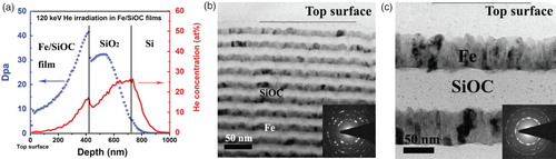
To maximize displacement creation efficiency and minimize He doping in the films, 120 keV He ions were selected for the irradiation. Different fluences of 2 × 10²¹, 5 × 10²¹ and 8 × 10²¹ ions/m2 were applied to examine the structure evolution as a function of doses. Figure (a), 1(b) and 1(c) shows the depth profiles of dpa values and helium concentrations in the Fe, thin and thick Fe/SiOC films with a fluence of 2 × 10²¹ ions/m2, respectively. The results were obtained by using the SRIM simulation.[Citation15] Because the dpa values and helium concentrations of the films are proportional to the total fluence, the damage depth profile of other fluences can be obtained by multiplying the factor of fluence. From Figure (a) and 1(b), the He+ irradiation with a dose of 2 × 10²¹ ions/m2 results in an approximate average of 5.5 dpa in the pure Fe films and 8 dpa in the Fe layers of the Fe/SiOC multilayer films. For the simulation of Fe/SiOC multilayers, the dpa value in Fe layers is approximately 3–4 times higher than that of the SiOC layer next to it. For pure Fe films, the majority of He ions came to rest in the Si substrate, while in irradiated Fe/SiOC composite films, there was a negligible amount of He in the near-surface region (<200 nm) and a notable amount of He close to the film/substrate interface. Therefore, the surface regions were selected in this study for examining pure irradiation-induced defect formation effects.
Figure 1. The depth profile of radiation damage and helium concentration for (a) nanocrystalline Fe, (b) thick and (c) thin Fe/SiOC multilayer which is simulated by SRIM (dose of 2 × 10²¹ ions/m2).
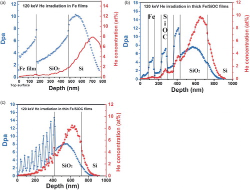
Figure (a) and 2(b) shows the cross-sectional TEM micrographs of thin and thick Fe/SiOC films after irradiation to 8 dpa at RT. The SiOC layers retain their amorphous state and no defect clusters are observed in the Fe layer. The glassy features are further confirmed by corresponding selective area diffraction (SAD) patterns shown as insets in Figure (a) and 2(b), respectively. Both SAD patterns exhibit ring diffraction patterns with similar interval spacing, suggesting body-centered cubic (BCC) structure of Fe. In addition, a diffuse halo around the central beam indicates the amorphous nature of the SiOC layers. The results suggest that Fe/SiOC crystalline/amorphous interfaces and Fe grain boundaries act as highly efficient defect sinks, enhancing point-defect recombination in Fe and maintaining the amorphous structure in SiOC. For thick Fe/SiOC films after irradiation, sharp Fe/SiOC interfaces are clearly observed, indicating no irradiation-induced mixing or no secondary phase formation between the Fe layers and the amorphous SiOC layers. Compared with thick Fe/SiOC films after irradiation, the thin Fe/SiOC sample develops amorphous intermixed layers between Fe and SiOC layers near the film/substrate region. Figure (c) shows the typical TEM micrograph of those amorphous intermixed layers. Energy-dispersive X-ray (EDX) spectroscopy results, not shown here, indicate that the intermixed layer consisted of Fe, Si and O elements. At this point, it is unclear why intermixing is observed in the thin Fe/SiOC multilayers. One possibility is the greater number of interfaces adds an addition mixing driving force to the system, as suggested by Liu et al. [Citation16,Citation17] Liu et al. have shown that interfaces can assist ion-beam mixing in several immiscible metallic systems even with a large positive heat of mixing.
Figure 2. The typical cross-sectional TEM images of (a) thin, (b) thick Fe/SiOC multilayers after RT irradiation (dose of 2 × 10²¹ ions/m2). (c) A high-magnification cross-sectional TEM micrograph of thin Fe/SiOC multilayer exhibiting an intermixed layer between Fe and SiOC layers. (d) The intermixed layer thickness as a function of damage levels in Fe layers. (e) The EDX line scan results of thin Fe/SiOC multilayers after RT irradiation (dose of 2 × 10²¹ ions/m2).
Because there is a damage level gradient in the multilayer samples, as seen in Figure (b), the averaged intermixed layer thickness as a function of damage in Fe layers can be calculated, and is plotted in Figure (d). It is shown that the averaged intermixed layer thickness increases in a linear manner as the damage level increases in the dpa range from approximately 4.5 to 14. After 14 dpa, there is little further intermixing. To depict the overall trend of intermixed layer thickness as a function of damage level up to approximately 56 dpa, the results obtained in thin Fe/SiOC sample after an approximate 32 dpa irradiation (Figure (a) and 3(b)) are also plotted as red points in Figure (d). To examine any difference in the chemical components for the intermixing layer under different dpa, EDX spectroscope element line scan has been carried out for the first 5 alternating Fe/SiOC layers, seen in Figure (e). The EDX results present similar Fe/Si EDX peak shape and width, suggesting that the chemical components for the intermixing layer do not vary under different dpa. The results indicate that the existence of an intermixed layer blocks further Fe, Si and O diffusion, which benefits the layer stability in accord with previous results.[Citation18] It is also interesting to note that the intermixed layer (FexSiyOz) is amorphous after irradiation. Wang et al. reported that fayalite (Fe2SiO4) was easily amorphized at doses <0.2 dpa.[Citation19] Therefore, the crystalline/amorphous interface transforms from a Fe/SiOC interface to a Fe/FexSiyOz interface and keeps acting as a point-defect sink.
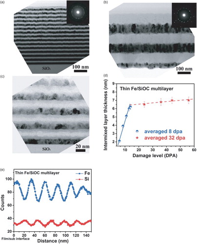
Figure 3. The typical cross-sectional TEM images of (a) thin, (c) thick Fe/SiOC multilayers after RT irradiation (dose of 8 × 10²¹ ions/m2). The corresponding scanning transmission electron microscopy (STEM) images are shown as (b) and (d), respectively.
To further investigate the structural stability of Fe/SiOC films at increased fluence, He+ irradiations with a dose of 8 × 10²¹ ions/m2 were conducted. The typical cross-sectional TEM images of thin and thick Fe/SiOC multilayers after irradiation with a dose of 8 × 10²¹ ions/m2 are shown in Figure (a) and 3(c), respectively. With such a high dose, the average damage level in Fe/SiOC reaches up to 32 dpa. However, there is no layer breakdown for either thin or thick multilayer samples. Meanwhile, the Fe layers retain a BCC structure and the SiOC layers remain amorphous, which is confirmed by the corresponding SAD patterns shown as insets of Figure (a) and 3(c). Both the SiOC and Fe layers show no evidence of void formation at this dpa level. To further examine the composition profile of thin and thick Fe/SiOC multilayers after 32 dpa irradiation, scanning transmission electron microscopy (STEM) was conducted under a high-angle annular dark field condition. The corresponding STEM images of Figure (a) and 3(c) are presented as Figure (b) and 3(d), respectively, where the contrast is roughly proportional to the atomic number square (Z2, also called Z-contrast imaging). Figure (b) clearly exhibits an alternating Fe and SiOC layer structure. A light contrast layer is observed between the bright contrast Fe layer and the dark contrast SiOC layer, indicating the formation of a FexSiyOz layer. Note that the thickness of all FexSiyOz layers is approximately 7 nm. These data show that the layer structure is maintained up to 32 dpa and that the FexSiyOz layer thickness does not further increase at these damage levels. Compared with thin Fe/SiOC multilayers, there is no intermixed layer observed for the thick Fe/SiOC multilayer samples after irradiation. A very clear Fe/SiOC interface is visible in Figure (d). All of the results demonstrate that these crystalline/amorphous interfaces can act as highly efficient defect sinks to enhance point-defect recombination, therefore benefiting the structure stability.
Because both crystalline/amorphous interfaces and Fe grain boundaries are capable of assisting defect annihilation, a question naturally arises as to whether only crystalline/amorphous interfaces or only Fe grain boundaries work as efficient defect sinks in preventing defect complex formation and in maintaining layered structure stability. To address the question, the irradiations were conducted on pure α-Fe films. Figure (a) and 4(c) presents the typical cross-sectional TEM images of pure α-Fe film after RT irradiation with a dose of 2 × 10²¹ and 5 × 10²¹ ions/m2, respectively. There are no indications of defect cluster formation in the nanocrystalline Fe films after 5.5 and 13.8 dpa irradiation. Compared with bulk Fe, small defect clusters have been observed even after 0.01 dpa irradiation.[Citation20,Citation21] The presence of a large density of grain boundaries results in the suppression of defect cluster formation in nanocrystalline Fe films and similar results have been shown in recent simulation work.[Citation4,Citation5] The other main feature in irradiated pure Fe films is the increased Fe grain size, which is also observed in Fe/SiOC multilayer systems.
Figure 4. The typical cross-sectional TEM images of (a) Fe film, (b) thick Fe/SiOC multilayers after RT irradiation (dose of 2 × 10²¹ ion/m2). Microstructure evolution of Fe film and thick Fe/SiOC multilayer after RT irradiation with a dose of 5 × 10²¹ ion/m2 is shown as (c) and (d), respectively.
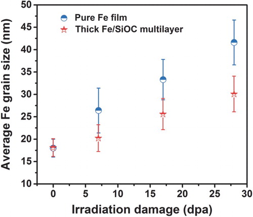
To have a fair comparison with irradiated pure Fe films (Figure (a) and 4(c)), cross-section TEM micrographs of thick Fe/SiOC films with same dose are shown as Figure (b) and 4(d), respectively. Figure summarizes the averaged Fe grain size as a function of irradiation damage level in both pure Fe films and thick/SiOC multilayer samples. It can be seen that, under the same irradiation damage level, there is a sharper increase in Fe grain size in pure Fe films compared to that in the thick Fe/SiOC multilayer sample. The primary reason for the increased Fe grain size after irradiation is irradiation-enhanced diffusion. Irradiation processes result in multi-displacement cascades which create isolated defects (vacancies and interstitials) and defect clusters. The surviving isolated defects and defect clusters increase the overall concentration of mobile defects of the system, which is directly related to the diffusion rate.[Citation22] The smaller increase in Fe grain size in the Fe/SiOC multilayer system suggests that there is a lower concentration of mobile defects in Fe/SiOC multilayers compared to that in the pure Fe layer during irradiation. This implies that not only the Fe grain boundaries, but also the crystalline/amorphous interfaces are acting as efficient defect sinks to promote interstitials and vacancies recombination and to enhance the irradiation stability of the system.
Figure 5. The average grain size in Fe film and thick Fe/SiOC multilayer as a function of dpa level. Grain size in pure Fe film has a sharper increase compared to that of the thick Fe/SiOC multilayer sample.
In summary, we examined the dose-dependent radiation stability of the Fe/SiOC composite system after RT irradiation. An average of approximately 8, 20 and 32 dpa of damage was applied in these films. After irradiation, no point-defect clusters were observed in the Fe and SiOC layers and the SiOC layers remained amorphous. For thick Fe/SiOC multilayers, clear Fe/SiOC interfaces remained and no irradiation-induced mixing was observed, suggesting good stability of the crystalline Fe/amorphous SiOC interface and RT radiation stability. For thin Fe/SiOC multilayers, the layered structure remained even after a 32 dpa irradiation, but an amorphous FexSiyOz intermixed layer formed between the Fe and SiOC layers during irradiation. The averaged intermixed layer thickness increased linearly as the damage level increased in the dpa range from approximately 4.5 to 14. After 14 dpa, there was little or no increase in the intermixed layer thickness. The new crystalline Fe/amorphous FexSiyOz interface also acted as an efficient defect sink. Fe grain growth was observed in both pure Fe layers and Fe/SiOC multilayers after irradiation. But the Fe grain growth was less in Fe/SiOC multilayers compared to that in pure Fe films, indicating greater suppression of irradiation-enhanced diffusion in Fe/SiOC multilayers. All the findings strongly support that Fe/SiOC, Fe/FexSiyOz crystalline/amorphous interfaces and Fe grain boundaries act as efficient defect sinks, benefiting overall structure stability.
Disclosure statement
No potential conflict of interest was reported by the authors.
Additional information
Funding
References
- Odette GR, Alinger MJ, Wirth BD. Recent developments in irradiation-resistant steels. Annu Rev Mater Res. 2008;38:471–503. doi: 10.1146/annurev.matsci.38.060407.130315
- Was GS. Materials degradation in fission reactors: lessons learned of relevance to fusion reactor systems. J Nucl Mater. 2007;367–370, Part A:11–20.
- Beyerlein IJ, Demkowicz MJ, Misra A, Uberuaga BP. Defect-interface interactions. Prog Mater Sci. 2015;74:125–210. doi: 10.1016/j.pmatsci.2015.02.001
- Chen D, Wang J, Chen TY, Shao L. Defect annihilation at grain boundaries in alpha-Fe. Sci Rep-UK. 2013;3:1450.
- Bai XM, Voter AF, Hoagland RG, Nastasi M, Uberuaga BP. Efficient annealing of radiation damage near grain boundaries via interstitial emission. Science. 2010;327:1631–1634. doi: 10.1126/science.1183723
- Odette GR, Hoelzer DT. Irradiation-tolerant nanostructured ferritic alloys: transforming helium from a liability to an asset. JOM-US. 2010;62:84–92. doi: 10.1007/s11837-010-0144-1
- Wong CPC, Nygren RE, Baxi CB, et al. Helium-cooled refractory alloys first wall and blanket evaluation. Fusion Eng Des. 2000;49–50:709–717. doi: 10.1016/S0920-3796(00)00176-9
- Misra A, Demkowicz MJ, Zhang X, Hoagland RG. The radiation damage tolerance of ultra-high strength nanolayered composites. JOM-US. 2007;59:62–65. doi: 10.1007/s11837-007-0120-6
- Fu EG, Misra A, Wang H, Shao L, Zhang X. Interface enabled defects reduction in helium ion irradiated Cu/V nanolayers. J Nucl Mater. 2010;407:178–188. doi: 10.1016/j.jnucmat.2010.10.011
- Li N, Fu EG, Wang H, et al. He ion irradiation damage in Fe/W nanolayer films. J Nucl Mater. 2009;389:233–238. doi: 10.1016/j.jnucmat.2009.02.007
- Nastasi M, Su Q, Price L, et al. Superior radiation tolerant materials: amorphous silicon oxycarbide. J Nucl Mater. 2015;461:200–205. doi: 10.1016/j.jnucmat.2015.02.039
- Colón Santana JA, Mora EE, Price L, Balerio R, Shao L, Nastasi M. Synthesis, thermal stability and the effects of ion irradiation in amorphous Si–O–C alloys. Nucl Instrum Methods Phys Res Sect B: Beam Interact Mater Atoms. 2015;350:6–13. doi: 10.1016/j.nimb.2015.02.074
- Brimbal D, Meslin E, Henry J, Decamps B, Barbu A. He and Cr effects on radiation damage formation in ion-irradiated pure iron and Fe-5.40 wt.% Cr: a transmission electron microscopy study. Acta Mater. 2013;61:4757–4764. doi: 10.1016/j.actamat.2013.04.070
- Su Q, Price L, Colon Santana JA, Shao L, Nastasi M. Irradiation tolerance of amorphous SiOC/crystalline Fe composite. Mater Lett. 2015;155:138–141. doi: 10.1016/j.matlet.2015.04.085
- Ziegler JF, Biersack JP, Littmark U. The stopping and range of ions in solids. New York: Pergamon Press; 1985.
- Li ZC, Yu DP, Liu BX. Manipulation of ordered layered structures by interface-assisted ion-beam mixing in immiscible Ag-Co and Ag-Ni systems. Phys Rev B. 2002;65:245403. doi: 10.1103/PhysRevB.65.245403
- Zhang ZJ, Jin O, Liu BX. Anomalous alloying behavior induced by ion irradiation in a system with a large positive heat of mixing. Phys Rev B. 1995;51:8076–8085. doi: 10.1103/PhysRevB.51.8076
- Su Q, Jian J, Wang H, Nastasi M. Thermal stability of amorphous SiOC/crystalline Fe composite, submitted for publication.
- Wang LM, Gong WL, Wang SX, Ewing RC. Comparison of ion-beam irradiation effects in X2YO4 compounds. J Am Ceram Soc. 1999;82:3321–3329. doi: 10.1111/j.1151-2916.1999.tb02246.x
- Zinkle SJ, Singh BN. Microstructure of neutron-irradiated iron before and after tensile deformation. J Nucl Mater. 2006;351:269–284. doi: 10.1016/j.jnucmat.2006.02.031
- Arakawa K, Imamura R, Ohota K, Ono K. Evolution of point defect clusters in pure iron under low-energy He+ irradiation. J Appl Phys. 2001;89:4752–4757. doi: 10.1063/1.1357785
- Dienes GJ, Damask AC. Radiation enhanced diffusion in solids. J Appl Phys. 1958;29:1713–1721. doi: 10.1063/1.1723032