
Abstract
The irradiation stability of amorphous SiOC and crystalline Fe interface was investigated by in-situ Kr ion mixing. Results showed intermixing between Fe and SiOC was most severe for irradiation at 50 K and the intermixing decreases as irradiation temperature increases. These findings suggest two characteristic regimes of ion mixing: one regime is independent of temperature and due to ballistic mixing and the other regime is dependent on temperature and is referred to as radiation-enhanced demixing. The occurrence of the temperature-independent mixing and temperature-dependent demixing regimes indicates that the Fe/SiOC nanocomposite is thermodynamically stable and radiation tolerant at elevated temperatures.
IMPACT STATEMENT This report reveals two characteristic ion mixing regimes in Fe/SiOC system: one temperature-independent regime and the other temperature-dependent demixing regime, indicating its thermodynamically stability and radiation tolerance at elevated temperatures.
GRAPHICAL ABSTRACT
Ion-beam irradiation of solids results in significant local rearrangement of atoms.[Citation1] In the case of composited systems containing two or more different materials, the most obvious example is ion mixing and alloying during ion irradiation which can occur at their interfaces.[Citation2–4] As one of few measureable quantities which is directly correlated to damage level, ion mixing has been studied in many solids.[Citation5] Previous systematic experimental results have shown that not only irradiation parameters (such as temperature, dose and dose rate but materials properties (such as heat of mixing and cohesive energy) influence the ion mixing process.[Citation6,Citation7] For example, an early observation of the ion mixing phenomenon suggests a temperature-independent ion mixing regime at low temperature and a temperature-dependent ion mixing regime at elevated temperatures.[Citation8,Citation9] At low temperatures, information is provided about ballistic effects on ion mixing because long-range defect migration is suppressed, and the system can be more easily driven from its equilibrium state. Mixing at elevated temperatures, where diffusion of radiation-induced defects can occur, tends to restore the system toward equilibrium or an energy favorable state.[Citation10] Heat of mixing between two solids also plays a crucial role in determining the ion mixing process.[Citation7] Take two solid systems Au on Cu and W on Cu for example,[Citation11] the former one has a negative heat of mixing while the later one has a positive heat of mixing. If one considered only ballistic models, both systems should have similar response to ion mixing due to their nearly identical parameters such as atomic number, atomic mass and atomic density. However, Au and Cu are well intermixed but W and Cu are barely mixed for the same irradiation conditions.[Citation12] Hence, how different solids mix under ion irradiation can be used to examine their interface stability.[Citation13,Citation14]
The present investigation was undertaken to examine the interface stability between crystalline Fe and amorphous silicon oxycarbide (SiOC). The crystalline Fe/amorphous SiOC system was selected due to two main reasons. First, amorphous SiOC is promising for use under extreme conditions because its crystallization temperature is in excess of 1300°C and it possess good oxidation and creep resistance.[Citation15–19] As a new kind of irradiation tolerant material, amorphous SiOC has been recently shown that its amorphous microstructure remains unchanged after irradiation. Studies have shown that SiOC alloys remain amorphous after both He and Kr irradiation at temperature ranges from room temperature to 600°C with damage levels up to 20 displacements per atom (dpa).[Citation20–22] These findings suggest irradiation-induced damage in this material, over a wide envelope of irradiation conditions, anneals out as fast as it is created.
Second, for potential service in extreme irradiation environments, amorphous SiOC can be paired with a crystalline metal component to form a composite for better heat conductivity and improved mechanical properties.[Citation23,Citation24] For such a situation it will be important to know if the SiOC/metal interface will be stable during irradiation. One example of such a composite is the Fe/SiOC system, which has exhibited promising thermal and radiation tolerant properties.[Citation24–27] An interesting feature of the Fe/SiOC system is that it is composed of crystalline metal and amorphous ceramic. Previous studies mainly focus on mixing in either crystalline/crystalline or amorphous/amorphous systems.[Citation2,Citation3,Citation28,Citation29] One observation was that ion mixing in amorphous materials exceeds 2–3 times than that observed in the crystalline counterpart, which was attributed to the more open structure and less long-range order in amorphous solids.[Citation30] At present, the crystalline metal/amorphous ceramic interface response to ion mixing is still largely unknown. In this study, the Fe/SiOC interface mixing and stability are investigated using a marker specimen where one Fe layer is embedded between two amorphous SiOC layers. In-situ Kr irradiation at 50 Kelvin (K), room temperature, 423 and 573 K were carried out to understand irradiation response of the crystalline/amorphous Fe/SiOC interface.
In this work, magnetron sputtering was used to fabricate a marker sample (SiOC/Fe/SiOC, 200/7/200 nm). Prior to depositions, the base pressure was 8.0 × 10⁻⁶ Pa or lower. The Ar partial pressure used for film deposition was ∼0.65 Pa. DC magnetron sputtering was used to synthesize the α-Fe layer while radio frequency co-sputtering was used to prepare amorphous SiOC layers from SiC and SiO2 targets at room temperature.
All cross-sectional specimens for transmission electron microscopy (TEM) were prepared by conventional grinding and polishing, followed by an ion milling process. To reduce the ion milling-induced damage, low energy (3.5 keV) and low angle (5°) were used in sample preparation. The cross-sectional microstructure of SiOC/Fe/SiOC marker specimens before and after irradiation was examined by an FEI Tecnai G2 F20 microscope operated at 200 keV. All images were taken at condition with zero sample tilt. A set of SiOC/Fe/SiOC marker specimens were in-situ irradiated with 1 MeV Kr ions at the IVEM-TANDEM facility at Argonne National Laboratory, where an ion accelerator is attached to a HITACHI H-9000NAR microscope with an operation voltage of 200 keV. Irradiation temperatures were 50, 298, 423 and 573 K. The real sample temperature varied by ±5°C as read by the thermocouple. The diameter of ion beam size was 1.5 mm (without rastering), which was able to cover the whole TEM specimen. Depth-dependent damage and defect concentration profiles were calculated by the Stopping and Range of Ions in Matter (SRIM)-2008 using the ion distribution and quick calculation of damage option in the SRIM software.[Citation31] The displacement energies for Fe were taken as 40 eV. The recoil distribution of Si and Fe elements at the Fe/SiOC interface was simulated by using the detailed calculation with full damage cascades option in SRIM-2008.
To examine the irradiation stability of the interface between Fe and SiOC, 1 MeV Kr ions were selected for the irradiation of these marker samples. SRIM calculated Kr projected ranges for Fe and SiOC are 241.3 and 700.2 nm, respectively. Because the simulated ranges far exceeded the thickness of the specimens (∼100 nm), the amount of Kr in the marker specimens was negligible. The geometry for the in-situ irradiation experiment where both the electron beam and the accelerated Kr ions bombard the TEM specimen with an incident angle of ∼15°. A typical cross-sectional TEM image of the marker sample is shown in Figure (a). An Fe layer with a thickness of 7 nm is sandwiched between two amorphous SiOC layer with a thicknesses of 200 nm. Because the Kr++ ion incident beam has a 75° angle to the specimen (seen as Figure (b)), ion mixing at the Fe/SiOC interface can vary: Kr ions can bombard SiOC side first in one case or it can hit the Fe layer in the other case. To qualitatively describe the ion mixing between Fe and SiOC, an analysis of the ballistic mixing was made with SRIM using a sample represented by SiOC/Fe/SiOC (25/50/25 nm). The Si and Fe recoil distribution profiles at the two Fe/SiOC interfaces, which are presented as Figure (c), were used to examine the ballistic intermixing between Fe and SiOC. The inset is the magnified element shows the recoil distribution at the interface region, which suggests ∼4 nm of intermixing due to ballistic processes.
Figure 1. (a) A typical cross-sectional TEM image of the marker sample. (b) A schematic of how the incident Kr beam interacts with the marker sample. (c) SRIM-simulated Si and Fe recoil distribution profiles at the two Fe/SiOC interfaces by using the detailed calculation with full damage cascades option.
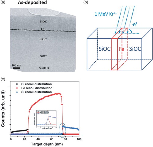
Figure (a) shows a typical cross-sectional bright-field TEM micrograph of marker specimen before Kr irradiation where one Fe layer is in between two amorphous SiOC layers with clear interfaces. The as-deposited Fe marker layer exhibits a typical columnar structure with 7 nm thickness while both SiOC layers show uniform contrast. The selective area diffraction (SAD) pattern of the marker sample is shown as insets of Figure (a) and exhibits a diffuse halo around the central beam, suggesting the amorphous nature of the SiOC layers. Although the contrast of the crystalline ring diffraction pattern is weak because of the thin Fe marker layer, the pattern shows similar interval spacing, indicating the body-centered cubic structure of Fe.
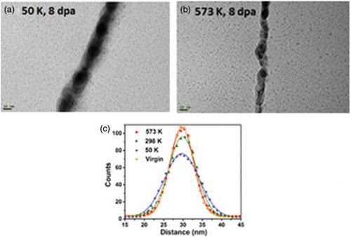
Figure 2. Typical cross-sectional bright-field TEM micrographs of marker specimen (a) before and after (b) 50 K, (c) 298 K, (d) 423 K, (e) 573 K irradiation. (f) The scanning transmission electron microscopy (STEM) image of marker specimen after 573 K irradiation.
To investigate the radiation stability of the Fe/SiOC interface as a function of temperature, in-situ irradiations were performed at 50, 298, 423 and 573 K. The microstructure evolutions of the marker samples after irradiation at 50, 298, 423 and 573 K with dose of 4.5 × 10¹⁵ ions/cm2 are present as Figure (b)–(e), respectively. The most important feature observed from these data is less intermixing and higher radiation stability at elevated temperatures. This is in contrast with metallic and metal-semiconductor systems with negative heat of mixing where the amount of mixing increases with irradiation temperature in the temperature-dependent mixing regime.[Citation6] The Fe/SiOC results suggest that the heat of mixing for this system is positive and the ion mixing mechanism at the Fe/SiOC interface is due primarily to ballistic mixing. In general, as an ion bombards a solid (marker sample in this study), it slows down and transfers nuclear and electronic energy to the solid. Due to the nuclear stopping of this process, target atoms can be displaced permanently from their original lattice sites and relocated a certain distance away. If this process occurs at the boundary of two materials (like Fe/SiOC interface), it leads to ion mixing. The amount of the ion mixing depends on ion species, ion dose and materials properties, etc.[Citation6] When the temperature of irradiation is as low as 50 K, the thermal energy for mixed atoms to diffuse is negligible. Therefore, ballistic effects play a key role in determining the extent of intermixing between Fe and SiOC atoms. At 50 K, the thickness of Fe marker layer broadens from 7 nm to approximate 20 nm, As the irradiation temperature increases, thermal energy is sufficient to enable atomic movement after the collision phase of the cascade, which can allow for demixing.[Citation10] The marker layer thickness at room temperature and 573 K irradiation is 11 and 8 nm, respectively. Comparison with the extensive layer broadening (20 nm) for the 50 K irradiation suggests that intermixed Fe and SiOC atoms de-mix at elevated temperatures indicative of an immiscible system. The Fe/SiOC interfaces are all clearly observed after the 573 K irradiations. The corresponding SAD pattern (inset of Figure (e)) further demonstrates no irradiation-induced mixing or secondary phase formation between the Fe marker layer and the amorphous SiOC layers.
To further examine the composition profile of the marker samples after irradiation, scanning transmission electron microscopy (STEM) and Energy dispersive X-ray spectroscopy (EDS) line scans were conducted. The typical STEM images of the marker sample after 573 K irradiation is shown as Figure (f). In order to quantify the amount of ion mixing between Fe and SiOC under Kr irradiation at different temperatures, EDS line scans were carried out for these marker samples after irradiation. The data in Figure present the EDS line scan yield as a function of scan length for the Fe marker layer irradiated at different temperatures. In this study, we take standard derivation (σ) from Gaussian fitting of the EDS line scans as the spreading of the marker layer. The irradiation-induced spreading can be determined by the change of variance before and after irradiation.
(1)
Figure 3. The typical EDS line scan yield of the Fe marker layer irradiated at different temperatures where a Gaussian function is used to fit these data.
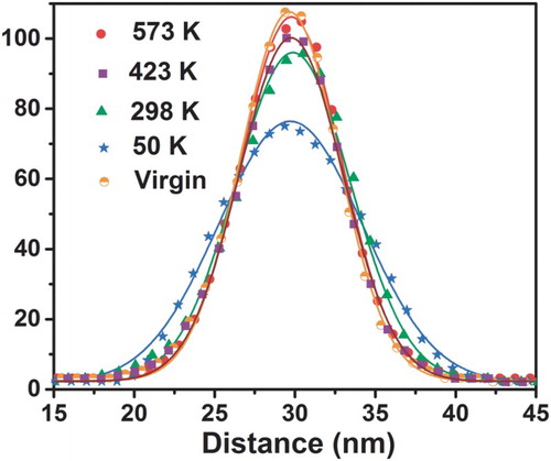
Gaussian fittings give the standard derivation for marker layer before and after irradiation at 573, 423, 298 and 50 K is 3.08, 3.12, 3.31, 3.56, 4.47 nm, respectively. By using Equation (1), layer spreading is calculated as 3.2, 1.8, 1.2, 0.50 nm for irradiation at 50, 298, 423 and 573 K, respectively. The layer spreading at 50 K is similar in magnitude to the mixing predicted by SRIM (Figure (d)).
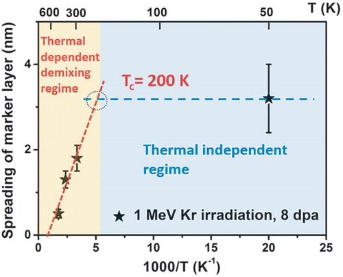
Considering that the Fe marker layers are zigzag due to shadowing effects during sputtering deposition, several EDS line scans were performed at each marker samples after irradiation. The error bar was estimated by taking into account the error from Fe layer spreading at different locations (seen as Figure ). The trend of the amount of ion mixing as a function of irradiation temperature is summarized and plotted as Figure where the results suggest a thermally dependent mixing regime and a thermally independent mixing regime. The transition temperature between the temperature-dependent and temperature-independent mixing regimes is ∼200 K, which is the intercept of the extrapolation of both regimes.
Figure 4. Summary of the amount of ion mixing as a function of irradiation temperature. The results suggest a thermally dependent demixing regime and a thermally independent mixing regime.
In summary, the Fe/SiOC interface exhibits better Kr radiation stability at elevated temperature (573 K) than that at low temperature (50 K). The results suggest the occurrence of temperature-independent mixing and temperature-dependent demixing regimes for Fe/SiOC system. The findings deliver a new understanding of how SiOC/Fe amorphous/crystal interfaces effect, influence, and enhance irradiation tolerance. This information can be used to aid in the potential design of amorphous ceramic/metal composites for service in extreme irradiation environments with significantly improved safety, performance and reliability.
Acknowledgements
The work was carried out in part in the Central Facilities of the Nebraska Center for Materials and Nanoscience. We also thank Peter M. Baldo, Meimei Li and Edward A. Ryan at Argonne National Laboratory for their help and discussion during in situ irradiation experiments. The IVEM facility at Argonne National Laboratory is supported by DOE-NE.
Disclosure statement
No potential conflict of interest was reported by the authors.
Additional information
Funding
References
- Matteson S, Nicolet MA. Ion mixing. Annu Rev Mater Sci. 1983;13:339–362. doi: 10.1146/annurev.ms.13.080183.002011
- Perez A, Abonneau E, Fuchs G, Treilleux M, Mchargue CJ, Joslin DL. Ion-beam mixing of metal ceramic interfaces. Nucl Instrum Methods B. 1992;65:129–138. doi: 10.1016/0168-583X(92)95025-M
- Nordlund K, Ghaly M, Averback RS. Mechanisms of ion beam mixing in metals and semiconductors. J Appl Phys. 1998;83:1238–1246. doi: 10.1063/1.366821
- Nastasi M, Hung LS, Mayer JW. Phase formation by ion-beam mixing in Ni/Al, Pd/Al, and Pt/Al Bilayers. Appl Phys Lett. 1983;43:831–833. doi: 10.1063/1.94511
- Averback RS. Fundamental-aspects of ion-beam mixing. Nucl Instrum Methods B. 1986;15:675–687. doi: 10.1016/0168-583X(86)90391-5
- Nastasi M, Mayer JW. Ion-beam mixing in metallic and semiconductor-materials. Mat Sci Eng R. 1994;12:1–52. doi: 10.1016/0927-796X(94)90005-1
- Cheng YT, Vanrossum M, Nicolet MA, Johnson WL. Influence of chemical driving forces in ion mixing of metallic bilayers. Appl Phys Lett. 1984;45:185–187. doi: 10.1063/1.95163
- Rehn LE, Okamoto PR. Recent progress in understanding ion-beam mixing of metals. Nucl Instrum Methods B. 1989;39:104–113. doi: 10.1016/0168-583X(89)90750-7
- Dereus R, Vredenberg AM, Voorrips AC, Tissink HC, Saris FW. Critical-temperatures for radiation enhanced diffusion and metastable alloy formation in ion-beam mixing. Nucl Instrum Methods B. 1991;53:24–34. doi: 10.1016/0168-583X(91)95441-F
- Fu CC, Dalla Torre J, Willaime F, Bocquet JL, Barbu A. Multiscale modelling of defect kinetics in irradiated iron. Nat Mater. 2005;4:68–74. doi: 10.1038/nmat1286
- Wang ZL, Westendorp JFM, Saris FW. Laser and ion-beam mixing of Cu-Au-Cu and Cu-W-Cu thin-films. Nucl Instrum Methods. 1983;209:115–124. doi: 10.1016/0167-5087(83)90789-5
- Westendorp H, Wang ZL, Saris FW. Ion-beam mixing of Cu-Au and Cu-W systems. Nucl Instrum Methods. 1982;194:453–456. doi: 10.1016/0029-554X(82)90563-8
- Paine BM, Averback RS. Ion-beam mixing - basic experiments. Nucl Instrum Methods B. 1985;7–8:666–675. doi: 10.1016/0168-583X(85)90451-3
- Bolse W. Mechanisms of ion beam induced atomic mixing in solids. Mat Sci Eng A Struct. 1998;253:194–201. doi: 10.1016/S0921-5093(98)00727-8
- Soraru GD, Suttor D. High temperature stability of sol-gel-derived SiOC glasses. J Sol-Gel Sci Technol. 1999;14:69–74. doi: 10.1023/A:1008775830830
- Soraru GD, Dallapiccola E, DAndrea G. Mechanical characterization of sol-gel-derived silicon oxycarbide glasses. J Am Ceram Soc. 1996;79:2074–2080. doi: 10.1111/j.1151-2916.1996.tb08939.x
- Harshe R, Balan C, Riedel R. Amorphous Si(Al)OC ceramic from polysiloxanes: bulk ceramic processing, crystallization behavior and applications. J Eur Ceram Soc. 2004;24:3471–3482. doi: 10.1016/j.jeurceramsoc.2003.10.016
- Rouxel T, Massouras G, Soraru GD. High temperature behavior of a gel-derived SiOC glass: elasticity and viscosity. J Sol-Gel Sci Technol. 1999;14:87–94. doi: 10.1023/A:1008779915809
- Rouxel T, Soraru GD, Vicens J. Creep viscosity and stress relaxation of gel-derived silicon oxycarbide glasses. J Am Ceram Soc. 2001;84:1052–1058. doi: 10.1111/j.1151-2916.2001.tb00789.x
- Nastasi M, Su Q, Price L, et al. Superior radiation tolerant materials: amorphous silicon oxycarbide. J Nucl Mater. 2015;461:200–205. doi: 10.1016/j.jnucmat.2015.02.039
- Colón Santana JA, Mora EE, Price L, Balerio R, Shao L, Nastasi M. Synthesis, thermal stability and the effects of ion irradiation in amorphous Si–O–C alloys. Nucl. Instrum. Methods Phys. Res. Sect B Beam Interact Mater Atoms. 2015;350:6–13. doi: 10.1016/j.nimb.2015.02.074
- Su Q, Cui B, Kirk MA, Nastasi M. Cascade effects on the irradiation stability of amorphous SiOC. Philos. Mag. Lett. 2016;96:60–66. doi:10.1080/09500839.2016.1147655.
- Odette GR, Alinger MJ, Wirth BD. Recent developments in irradiation-resistant steels. Annu Rev Mater Res. 2008;38:471–503. doi: 10.1146/annurev.matsci.38.060407.130315
- Su Q, Price L, Shao L, Nastasi M. Dose dependence of radiation damage in nano-structured amorphous SiOC/crystalline Fe composite. Mater Res Lett. 2016;4:48–54. doi: 10.1080/21663831.2015.1103796
- Su Q, Price L, Colon Santana JA, Shao L, Nastasi M. Irradiation tolerance of amorphous SiOC/crystalline Fe composite. Mater Lett. 2015;155:138–141. doi: 10.1016/j.matlet.2015.04.085
- Su Q, Jian J, Wang H, Nastasi M. Thermal Stability of Amorphous SiOC/Crystalline Fe composite. Philos Mag. 2015;95:3876–3887. doi: 10.1080/14786435.2015.1108527
- Su Q, Cui B, Kirk MA, Nastasi M. In-situ observation of radiation damage in nano-structured amorphous SiOC/crystalline Fe composite. Scr Mater. 2016;113:79–83. doi: 10.1016/j.scriptamat.2015.10.009
- Kraft S, Schattat B, Bolse W, et al. Ion beam mixing of ZnO/SiO2 and Sb/Ni/Si interfaces under swift heavy ion irradiation. J Appl Phys. 2002;91:1129–1134. doi: 10.1063/1.1425439
- Radek M, Bracht H, Posselt M, Liedke B, Schmidt B, Bougeard D. Temperature dependence of ion-beam mixing in crystalline and amorphous germanium isotope multilayer structures. J Appl Phys. 2014;115. doi: 10.1063/1.4861174
- Forbes DV, Coleman JJ, Klatt JL, Averback RS. Temperature-dependence of ion-beam mixing Iii-V semiconductors. J Appl Phys. 1995;77:3543–3545. doi: 10.1063/1.358583
- Ziegler JBB, JF, Littmark U. The stopping and range of ions in solids. New York: Pergamon Press; 1985.