
Abstract
We present a synthesis/processing method for fabricating ferrimagnetic insulator (Bi-doped yttrium iron garnet) thin films with tunable magnetic anisotropy. Since the desired magnetic properties rely on controllable thickness and successful doping, we pay attention to the entire synthesis/processing procedure (nanopowder synthesis, nanocrystalline target preparation and pulsed laser deposition (PLD)). Atomically flat films were deposited by PLD on (111)-orientated yttrium aluminum garnet. We show a significant enhancement of perpendicular anisotropy in the films, caused by strain-induced anisotropy. In addition, the perpendicular anisotropy is tunable by decreasing the film thickness and overwhelms the shape anisotropy at a critical thickness of 3.5 nm.
GRAPHICAL ABSTRACT
IMPACT STATEMENT
Strain-induced perpendicular magnetic anisotropy (PMA) in heavily Bi substituted YIG films for ferrimagnetic insulator based spintronic studies and devices.
High-quality oxide thin films are the basis for a wide range of optical and magnetic devices. Often the films must be doped to obtain the desired functionality, causing intense work on doped thin film growth by a variety of methods, including molecular beam epitaxy, sputtering and pulsed laser deposition (PLD). The popularity of PLD has increased recently because it has relatively low complexity, but is versatile and capable of yielding high-quality epitaxial films. The fundamental challenge in producing doped films is transferring the materials from a target to a substrate with the desired composition. Two different doping approaches are available: (1) using a doped target with desired constituent elements and (2) using multiple targets with different constituents as sources. Both have been successful, but the latter so-called combinatorial method requires more complex instrumentation [Citation1]; and since the cost and complexity of procedures are often the most important factors in the proliferation of materials in applications, the former approach is more desirable.
It is understandable that the PLD target’s characteristics (composition, microstructure and density) should affect film quality; however, there is relatively little work devoted to the processing science of target preparation. There has been some work in this regard in un-doped films. Jakeš et al. [Citation2] used a modified sol-gel (Pechini) technique to make precursors and simultaneously densified and reacted (solid-state reaction) the powders to make lithium niobate targets. They found that thin films prepared from their polycrystalline targets were smoother than those prepared from commercial single crystal targets, suggesting that grain boundaries play a positive role in film growth. Similarly, Kim et al. [Citation3] examined the effect of target density on PLD growth of polycrystalline TiO2 thin films, finding that higher density targets yielded smoother films. In work where successful doping was crucial, Sharma et al. [Citation4] demonstrated ferromagnetism in Mg-doped ZnO thin films. The films were grown by PLD from solid-state reacted sintered pellets; attention to detail in target preparation was important, since too high a sintering temperature resulted in the loss of ferromagnetism. In contrast to these previous studies, we ensure proper doping and phase homogeneity throughout the procedure,that is, from powder to bulk target to film. To obtain high-quality material, we opted for a chemical route for the synthesis of fine, nanocrystalline and homogeneously doped powder and then densified the powders to produce a dense PLD target without causing excessive grain growth using current-activated pressure-assisted densification (CAPAD).[Citation5] We then used this homogenous, highly dense nanocrystalline target in PLD.
The ferrimagnetic insulator yttrium iron garnet, Y3Fe5O12 (YIG), has drawn considerable attention for use in magneto-optical [Citation6,Citation7] and insulator-based spintronic devices.[Citation8–12] For spintronics, bilayer or multilayer structures containing YIG and a conducting material are often used and such structures require smooth films and high-quality interfaces. A common approach is to grow smooth epitaxial thin films on other garnet substrates (often yttrium aluminum garnet (YAG) or gadolinium gallium garnet (GGG)) by PLD. Due to lattice constant match, this results in the easy magnetic direction in the plane of the film dictated by the shape anisotropy. Recently, we have shown the well-controlled growth of atomically flat YIG films that display in-plane magnetization.[Citation13] For many fundamental studies as well as device applications, it is beneficial to have the magnetization out of plane, that is, induced perpendicular magnetic anisotropy (PMA). For example, in heterostructures of magnetic insulators and graphene, the exchange interaction provided by the magnetic insulator with PMA is expected to modify the electronic band structure of graphene, which consequently causes new physical phenomena such as the quantized anomalous Hall effect.[Citation14] Hence, controlling and tuning magnetic anisotropy have been a goal for various applications.[Citation10,Citation15] In this work, we report a synthesis and processing procedure to engineer magnetic anisotropy in YIG-based films using the dual approach of strain induced by doping and substrate thermal expansion mismatch. We chose the heavily doped Bi1.5Y1.5Fe5O12 stoichiometry to achieve this goal, for reasons discussed below.
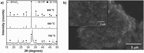
A polymeric solution-based, organic/inorganic entrapment route was employed to synthesize Bi-substituted YIG powders, Bi1.5Y1.5Fe5O12. This route has been reported previously for other oxide-based systems.[Citation16,Citation17] Commercially available yttrium nitrate hexahydrate, Y(NO3)36H2O; iron nitrate nonahydrate, Fe(NO3)39H2O; and bismuth nitrate pentahydrate, Bi(NO3)35H2O, all from Alfa Aesar® were the precursor sources of the cations. The polymeric solution contains 5 wt% of 80% hydrolyzed polyvinyl alcohol (PVA, Sigma-Aldrich®) dissolved in ultra-high pure water by stirring for 24 h at room temperature. Stoichiometric amounts of chemical precursors were also dissolved and stirred for 24 h before the addition of the polymeric solution. The ratio of nitrate precursors to the PVA solution was chosen in such a way that there were four times more positively charged valences from the cations than negatively charged functional end groups of the PVA (i.e. −OH groups). This ensures that there were more cations in the solution than the hydroxyl functional groups of the polymer with which they could chemically bond. Then, the precursor solutions were mixed with the polymeric solution and a few drops of nitric acid(HNO3) were added to the solution to ensure that the pH of the solution was maintained around 0.25 to prevent gelation or precipitation during the reaction. Continuous stirring resulted in complete dissolution of the precursors and the clear solution was then heated on a hot plate (∼300°C) with continuous stirring until the water in the solution formed a thick dark brown resin. The aerated resin formed was then vacuum dried at 125°C for 24 h. The vacuum drying process resulted in a brownish dried crisp foam, which was first ground using an agate mortar and pestle and then heat-treated in air at 700°C for 30 min. We used thermal analysis (Differential Scanning Calorimetry/Thermogravimetric Analysis (TGA), TA Instruments) with a heating rate of 20°C/min in flowing air to understand the decomposition temperature regime, weight loss and crystallization temperature. Removing all the volatile matter is of paramount importance to obtain a dense target as well as to employ it in a high vacuum chamber for PLD. The TGA curve of the as-synthesized resin shows no weight loss observed above 700°C, indicating that all volatile material are removed at that temperature (data not shown here). The effect of annealing temperature on phase formation is shown in Figure (a). X-ray diffractometry (XRD) was performed with Cu Kα radiation (PANalytical Empyrean diffractometer) at room temperature using a step size of 0.013 and 30.60 s per step. XRD analysis of the powders calcined at 700°C for 30 min indicates primarily Bi-substituted perovskite phase (Bi:YIP) and Bi-substituted garnet as the secondary phase (Bi:YIG). The formation of YIP phases is commonly observed during the YIG synthesis due to its low energy of formation. Upon further heat treatment, the powders completely converted into the desired garnet structure (Bi:YIG) at temperatures of 800°C and higher with no remanence of the perovskite structure (Bi:YIP). There is also evidence of minor BiFeO3 present at 800°C and 900°C, which is not observed at 700°C. This is likely caused by these temperatures being near to or higher than the melting point of Bi2O3 (817°C), causing high reactivity of Bi2O3 with excess Fe2O3 associated with the formation of YIP. The advantage of working with the chemical precursor route is the excellent mixing of the starting precursors and high purity of the resultant oxides.[Citation18,Citation19] Good mixing of the starting materials ensures low processing temperature compared to conventional routes, which leads to fine crystallite size. This is visible in Figure (b) showing scanning electron microscopy (SEM, FEI NNS450) micrographs of powders calcined at 700°C for 30 min. The porous microstructure of the powder is typical of the steric entrapment synthesis method and facilitates the grinding process.[Citation17] Low-magnification SEM (images are not shown here) reveals that the particles are irregular in shape after initial grinding, ranging from 0.1 to 30 µm with majority being ∼0.5 µm. However, a higher magnification SEM micrograph of the particles revealing nanoscale features ranging from 54 to 190 nm can be seen in the inset in Figure (b).
Figure 1. Characterization of nanocrystalline Bi:YIG powder produced using the organic/inorganic entrapment route. (a) XRD of the powders heat-treated at various temperature for 30 min in air. (b) SEM images of the powders calcined at 700°C for 30 min. The inset is a higher magnification image of a powder particle revealing nanometer-size grains.
Powders calcined at 700°C were chosen for densification since they offer a good compromise between desired phases and grain size. The powders were then further grinded in order to reduce the particle sizes and to increase the specific surface area in preparation for bulk target processing. A graphite die of 19 mm diameter, with inside cavity wrapped with thin graphite foil, was employed to consolidate the crushed powders. Two thin graphite spacers were placed between the powder compact and the top and bottom plungers. The assembly was loaded into a custom-built, CAPAD setup,[Citation5] also known as spark plasma sintering, and 105 MPa pressure was uniaxially applied for 1 min. The pressure was maintained while the assembly was heated to 700°C at the rate of 150°C/min, held for 5 min and cooled down to room temperature at the same rate. This processing technique takes advantage of the benefits of the simultaneous application of electric current and pressure, which allows for dramatically decreased processing time and temperatures, making it possible to retain the nanostructure.[Citation20]
Figure (a) depicts the various stages of the consolidation involved during CAPAD after removing the equipment compliance under 105 MPa. In stage I, the compacted powders thermally expand due to the heat treatment involved. During stage II, when the die temperature is ∼275°C, densification starts to overcome the thermal expansion, resulting in major shrinkage. The sample continues to densify through the final temperature (700°C) until it reaches an asymptote at the end of the final stage III. In general, conventional processing of the Bi:YIG system over a range of Bi concentration on YIG requires either a high temperature (above 900–1,400°C), multiple heat treatments or holding for a longer time ranging from 1 to 24 h.[Citation21–23] By contrast, in the present work, the high heating rate combined with the applied pressure allowed full densification in less than 600 s at 700°C.
Figure 2. Characterization of nanocrystalline Bi:YIG dense targets processed using CAPAD. (a) Response of the powder compact during CAPAD processing under 105 MPa at the rate of 150°C/min. (b) XRD of densified specimen (Bi:YIG target) shows high homogeneity after the densification. The inset shows a magnified maximum intensity peak with a corresponding reference YIG peak (red color). (c) SEM micrograph of the fractured surface of the bulk sample revealing grain size ranging from 80 to 280 nm, with an average of 186 nm. The inset shows a picture of the target. (d) Hysteresis loop of the dense target showing soft magnetic behavior.
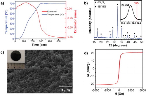
The XRD pattern of the CAPAD-processed target (Figure (b)) indicates the complete phase transformation to Bi:YIG (no evidence of Bi:YIP or BiFeO3 phases) during consolidation with minor Bi2O3 phase segregation. The absolute density of the bulk, dense material measured is 6.15 g/cm3, which corresponds to 97.3% of the theoretical density. The theoretical density of 6.32 g/cm3 is obtained using lattice parameter values measured on the powder samples heat-treated at 900°C for 30 min. Parameters from the powder sample rather than the bulk sample were used to avoid the influence of micro-strain, which could possibly deviate the lattice parameter values by peak broadening. The inset in Figure (b) shows the major peak of the consolidated sample in comparison with the standard YIG reference peak (red line); it clearly reveals that the substitution of Bi+3 on Y+3 site resulted in an increased lattice constant and shifted the peak toward a lower angle.
Microstructures of the fractured surface of the CAPAD-processed bulk sample are shown in Figure (c), revealing a fine-grained microstructure with some fine pores (≤1 µm); the average grain size is 186 nm (ranging from 80 to 280 nm). The inset in Figure (c) is a picture of the target (scale in cm). Back Scattered Electron images of polished surfaces (not shown here) showed no noticeable phase segregation. We attribute the fine homogenous microstructure to the optimized processing conditions, especially to the low densification temperature. Using higher temperatures and conventional solid-state processing would surely cause significant grain growth and possibly a heterogeneous microstructure since liquid phase sintering is the active densification mechanism (melting temperature of Bi2O3 is 817°C).[Citation22,Citation24]
The magnetic properties of the CAPAD-processed dense specimen were measured using a vibrating sample magnetometer (VSM) at room temperature with an applied magnetic field up to 10 kOe. Figure (d) shows a hysteresis curve of the Bi:YIG, indicating a soft magnetic behavior as expected. The saturation magnetization (Ms) is 21.1 emu/g, remanence (Mr) is 2.9 emu/g and an intrinsic coercive force (Hc) is 54 Oe. These values are consistent with previously reported values for the Bi:YIG system with similar compositions.[Citation18,Citation23]
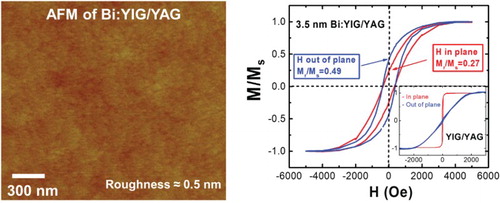
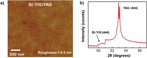
High-quality ultraflat Bi:YIG thin films were grown on (111)-oriented YAG substrates by the PLD system using the CAPAD-processed Bi:YIG targets. The substrates were first cleaned with acetone followed by isopropyl alcohol and deionized water. Prior to deposition, the substrates were annealed at moderate temperature ∼200°C overnight in high vacuum at the level of 10−7 Torr. After gradually increasing the substrate temperature to about 800°C and oxygen pressure with 12 wt% ozone to 1.5 mTorr, the KrF excimer laser pulses of 248 nm in wavelength with power of 150 mJ struck the target at a repetition frequency of 1 Hz. The deposition rate is estimated to be 1 Å/min. After deposition, the film was annealed under the same oxygen pressure for half an hour in order to enhance the crystalline structure before slowly decreasing the heater temperature and oxygen pressure. Atomic Force Microscopy (AFM) analysis (Figure (a)) indicates that atomically flat films with low roughness (∼0.5 nm) and no pin holes were found on films. XRD of the 7-nm thick Bi:YIG thin film grown on the YAG substrate shows the major YAG single crystal peak as expected, in addition to the Bi:YIG (444) peak (Figure (b)). In addition, the analysis reveals that the films contain no secondary phases (the peak at ∼51° is due to the YAG substrate).
Figure 3. Structural characterization of Bi:YIG films (a) AFM surface profile for Bi1.5Y1.5Fe3O12 YIG film with a root-mean-square roughness about 0.5 nm across a 2 µm × 2 µm scan area. (b) XRD pattern of the same Bi-doped YIG films grown on YAG (111).
In YIG thin films grown on the YAG substrate, magnetic anisotropy Ku is dominated by the shape anisotropy, resulting in the easy axis directed in-plane, as seen in the inset of Figure (a). One could tune the magnetic anisotropy by introducing a lattice-constant mismatch-induced magnetostriction.[Citation15,Citation25] Along the <111> orientation of cubic crystals, the magnetostriction effect-induced effective perpendicular anisotropy field is described as,[Citation26] where λ111, σ|| and Ms are the magnetostriction constant, in-plane stress and saturation magnetization, respectively. The negative value of λ111 (−4.45 × 10⁻⁶) in garnet films requires a tensile stress (σ|| > 0) in order to produce a positive perpendicular anisotropy field, needed for PMA. The stress is given by
, where
is the lattice constant perpendicular to the film, Y is Young’s modulus, µ is Poisson’s ratio and ao is the unstrained lattice parameter of the film. In BixY1−xFe3O12 films,[Citation27] in the regime where the Bi doping is light, it is found that an increasing Bi content x results in a larger perpendicular lattice constant based on a homogeneous elastic compression because of the small lattice mismatch. However, in the regime of heavy doping of Bi (x ≥ 1.5), the stress is accommodated by dislocations, especially at elevated growth temperatures. Due to the thermal expansion difference between the film and the substrate as the film is cooled back to room temperature, stress is built up at the interface at room temperature (region 2 in ref. [Citation27]). The strained lattice constant, in such heavily Bi-doped YIG is
, where
and
are the thermal expansion coefficient for the films and substrates, respectively, and ΔT is the difference between growth and room temperature.[Citation27] In this case, the films are subjected to a tensile strain, owing to the larger coefficient for the BixY1−xFe3O12 films
than that of substrates
. Therefore, in the large Bi-doping regime such as the x = 1.5 stoichiometry chosen here, it is promising to generate PMA in Bi:YIG films grown on YAG, thanks to the larger tensile strain.
Figure 4. (a) Normalized magnetic hysteresis loops for both field out-of-plane and in-plane geometries of 3.5 nm Bi1.5Y1.5Fe3O12 film grown on (111)-oriented YAG after removing the diamagnetic background of the substrates. Inset: normalized magnetic hysteresis loops for both out-of-plane and in-plane geometries of undoped YIG films grown on (111)-oriented YAG after removing the diamagnetic background of the substrates showing a strong in-plane anisotropy. (b) The thickness dependence of the squareness for Bi1.5Y1.5Fe3O12 films on YAG for both in-plane and out-of-plane indicating the enhancement of PMA for thinner films.
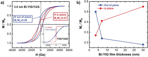
The magnetic property of the as-grown thin films was then measured using VSM and a superconducting quantum interference device (SQUID) Magnetometer. Figure (a) shows the normalized magnetic hysteresis loop of a 3.5 nm Bi1.5Y1.5Fe3O12 film grown on (111)-oriented YAG for both field out-of-plane and in-plane geometries after removing the diamagnetic background of the substrates. In contrast to similarly grown YIG films on YAG (inset of Figure (a)), the out-of-plane curve is comparable to the in-plane curve, clearly indicating an increase in PMA of the Bi:YIG film. We attribute the increase in PMA to interfacial strain caused by the difference in thermal expansion coefficients as discussed above. It is also a possibility that a Dzyaloshinskii–Moriya interaction (DMI) could contribute. In thin film heterostructures, DMI usually arises from the inversion symmetry broken at the interface. Both the DMI and PMA, to first approximation, are proportional to the strength of spin orbit coupling. In another set of experiments (not shown here), we have deposited Bi:YIG films on GGG, yielding similar results. In addition, we have deposited other rare earth iron garnets (Tm3Fe5O12) on the same combination of substrates (YAG and GGG) which also show strain-tunable PMA.[Citation28] Similar findings among different rare earth garnets on different substrates strongly suggest that interfacial strain is dominant over possible DMI. In order to further confirm that increase in PMA is an interfacially induced effect, we conducted a thickness dependence study. Figure (b) shows the Bi:YIG thickness dependence of the squareness of magnetic hysteresis loops defined as the ratio of remanence Mr over saturation magnetization Ms for both in-plane and out-of-plane. A strong enhancement of the squareness for out-of-plane and suppression of squareness for in-plane when Bi:YIG films become thinner suggest that the increase in PMA is caused by the interfacial strain. The PMA increases with a decrease in film thickness and overwhelms the shape anisotropy at a thickness of 3.5 nm.
In summary, we have presented an efficient method for the production of thin Bi:YIG films grown from well-doped nanocrystalline targets which were made from high-quality nanocrystalline powders. The films have strain-induced PMA from a combination of the Bi doping and thermal expansion mismatch. These results should be useful for the continued development of ferrimagnetic insulator-based spintronic studies and devices where PMA is important.
Disclosure statement
No potential conflict of interest was reported by the authors.
ORCiD
Pathikumar Sellappan http://orcid.org/0000-0002-7819-6336
Additional information
Funding
References
- Sposito A, Gregory SA, de Groot PAJ, Eason RW. Combinatorial pulsed laser deposition of doped yttrium iron garnet films on yttrium aluminium garnet. J Appl Phys. 2014;115:053102. Available from: http://scitation.aip.org/content/aip/journal/jap/115/5/10.1063/1.4864134. doi: 10.1063/1.4864134
- Jakeš V, Rubešová K, Erben J, Nekvindová P, Jelínek M. Modified sol–gel preparation of LiNbO3 target for PLD. Opt Mater (Amst). 2013;35:2540–2543. Available from: http://www.sciencedirect.com/science/article/pii/S0925346713004011. doi: 10.1016/j.optmat.2013.07.019
- Kim J-H, Lee S, Im H-S. The effect of target density and its morphology on TiO2 thin films grown on Si(100) by PLD. Appl Surf Sci. 1999;151:6–16. Available from: http://www.sciencedirect.com/science/article/pii/S016943329900269X. doi: 10.1016/S0169-4332(99)00269-X
- Sharma P, Gupta A, Rao KV, et al. Ferromagnetism above room temperature in bulk and transparent thin films of Mn-doped ZnO. Nat Mater. 2003;2:673–677. doi:10.1038/nmat984.
- Garay JE. Current-Activated, pressure-assisted densification of materials. Annu Rev Mater Res. 2010;40:445–468. Available from: http://www.annualreviews.org/doi/abs/10.1146/annurev-matsci-070909-104433. doi: 10.1146/annurev-matsci-070909-104433
- Nur-E-Alam M, Vasiliev M, Kotov Va, Alameh K. Highly bismuth-substituted, record-performance magneto-optic garnet materials with low coercivity for applications in integrated optics, photonic crystals, imaging and sensing. Opt Mater Express. 2011;1:413–427. doi: 10.1364/OME.1.000413
- Galstyan O, Lee H, Babajanyan A, Hakhoumian A, Friedman B, Lee K. Magneto-optical visualization by Bi:YIG thin films prepared at low temperatures. J Appl Phys. 2015;117:163914. Available from: http://scitation.aip.org/content/aip/journal/jap/117/16/10.1063/1.4918907. doi: 10.1063/1.4918907
- Sun Y, Song YY, Chang H, et al. Growth and ferromagnetic resonance properties of nanometer-thick yttrium iron garnet films. Appl Phys Lett. 2012;101:082405. Available from: http://link.aip.org/link/APPLAB/v101/i8/p082405/s1&Agg=doi. doi: 10.1063/1.4747465
- Onbasli MC, Kehlberger A, Kim DH, et al. Pulsed laser deposition of epitaxial yttrium iron garnet films with low Gilbert damping and bulk-like magnetization. APL Mater. 2014;2:106102. Available from: http://scitation.aip.org/content/aip/journal/aplmater/2/10/10.1063/1.4896936.
- Kehlberger A, Richter K, Onbasli MC, et al. Enhanced magneto-optic Kerr effect and magnetic properties of CeY2Fe5O12 epitaxial thin films. Phys Rev Appl. 2015;4:014008. Available from: http://link.aps.org/doi/10.1103/PhysRevApplied.4.014008. doi: 10.1103/PhysRevApplied.4.014008
- Jin L, Zhang D, Zhang H, et al. Spin valve effect of the interfacial spin accumulation in yttrium iron garnet/platinum bilayers. Appl Phys Lett. 2014;105:132411. Available from: http://scitation.aip.org/content/aip/journal/apl/105/13/10.1063/1.4897359. doi: 10.1063/1.4897359
- Jungfleisch MB, Lauer V, Neb R, Chumak AV, Hillebrands B. Improvement of the yttrium iron garnet/platinum interface for spin pumping-based applications. Appl Phys Lett. 2013;103:022411. Available from: http://scitation.aip.org/content/aip/journal/apl/103/2/10.1063/1.4813315. doi: 10.1063/1.4813315
- Tang C, Aldosary M, Jiang Z, et al. Exquisite growth control and magnetic properties of yttrium iron garnet thin films. Appl Phys Lett. 2016;108:102403. Available from: http://scitation.aip.org/content/aip/journal/apl/108/10/10.1063/1.4943210. doi: 10.1063/1.4943210
- Qiao Z, Yang SA, Feng W, et al. Quantum anomalous hall effect in graphene from Rashba and exchange effects. Phys Rev B. 2010;82:161414. Available from: http://journals.aps.org/prb/abstract/10.1103/PhysRevB.82.161414. doi: 10.1103/PhysRevB.82.161414
- Kubota M, Shibuya K, Tokunaga Y, et al. Systematic control of stress-induced anisotropy in pseudomorphic iron garnet thin films. J Magn Magn Mater. 2013;339:63–70. Available from: http://linkinghub.elsevier.com/retrieve/pii/S030488531300139X. doi: 10.1016/j.jmmm.2013.02.045
- Gülgün MA, Kriven WM, Nguyen MH. Processes for preparing mixed metal oxide powders [Internet]. United States Patent; 2002 [cited 2002 Nov 19]. Available from: http://www.google.com/patents/US6482387.
- Ribero D, Kriven WM. Synthesis of LiFePO4 powder by the organic–inorganic steric entrapment method. J Mater Res. 2015;30:2133–2143. Available from: http://journals.cambridge.org/abstract_S0884291415001818. doi: 10.1557/jmr.2015.181
- Fu Y-P, Cheng C-W, Hung D-S, Yao Y-D. Formation enthalpy and magnetic properties of Bi-YIG powders. Ceram Int. 2009;35:1509–1512. Available from: http://www.sciencedirect.com/science/article/B6TWH-4TBGF04-4/2/bf6766d31e3093b4d650993ae2206916. doi: 10.1016/j.ceramint.2008.08.005
- Lee H, Yoon Y, Kim S, et al. Preparation of bismuth substituted yttrium iron garnet powder and thin film by the metal-organic decomposition method. J Cryst Growth. 2011;329:27–32. Available from: http://linkinghub.elsevier.com/retrieve/pii/S0022024811005756. doi: 10.1016/j.jcrysgro.2011.06.048
- Gaudisson T, Acevedo U, Nowak S, et al. Combining soft chemistry and spark plasma sintering to produce highly dense and finely grained soft ferrimagnetic Y3Fe5O12 (YIG) ceramics. J Am Ceram Soc. 2013;96:3094–3099. doi:10.1111/jace.12452
- Wu YJ, Zhang T, Li J, Chen XM. Effects of bi-substitution on dielectric and ferroelectric properties of yttrium iron garnet ceramics. Ferroelectrics. 2014;458:25–30. Available from: http://www.tandfonline.com/doi/abs/10.1080/00150193.2013.849963. doi: 10.1080/00150193.2013.849963
- Zhao H, Zhou J, Li B, Gui Z, Li L. Microstructure and densification mechanism of low temperature sintering Bi-Substituted yttrium iron garnet. J Electroceram. 2008;21:802–804. Available from: http://link.springer.com/10.1007/s10832-007-9300-6. doi: 10.1007/s10832-007-9300-6
- Wu YJ, Yu C, Chen XM, Li J. Magnetic and magnetodielectric properties of Bi-substituted yttrium iron garnet ceramics. J Magn Magn Mater. 2012;324:3334–3337. Available from: http://linkinghub.elsevier.com/retrieve/pii/S0304885312004635. doi: 10.1016/j.jmmm.2012.05.045
- Zhao H, Zhou J, Bai Y, Gui Z, Li L. Effect of Bi-substitution on the dielectric properties of polycrystalline yttrium iron garnet. J Magn Magn Mater. 2004;280:208–213. doi: 10.1016/j.jmmm.2004.03.014
- Paoletti A, editor. Physics of magnetic garnets: Proceedings of the international school of physics proceedings, 1977. Amsterdam: Elsevier Science; 1978.
- Heinz DM. Mobile cylindrical magnetic domains in epitaxial garnet films. J Appl Phys. 1971;42:1243. Available from: http://scitation.aip.org/content/aip/journal/jap/42/4/10.1063/1.1660200. doi: 10.1063/1.1660200
- Chern M-Y, Liaw J-S. Study of BixY3-xFe5O12 thin films grown by pulsed laser deposition. Jpn J Appl Phys. 1997;36:1049–1053. Available from: http://iopscience.iop.org/article/10.1143/JJAP.36.1049. doi: 10.1143/JJAP.36.1049
- Tang C, Sellappan P, Liu Y, Garay JE, Shi J. Anomalous Hall effect in Tm3Fe5O12/Pt with engineered perpendicular magnetic anisotropy. Phys Rev Lett. 2016.