
ABSTRACT
Co-deformation behavior is a key issue for plasticity stability of heterogeneous nanolayered materials. Using indentation testing, we investigated the plastic deformation behavior of a Cu–Au nanolayered composite (NLC) with an individual layer thickness of 50 nm. We found that the softer Au layer exhibited less deformability than the harder Cu layer in the initial stage of deformation, while this abnormal phenomenon started to gradually disappear as the constituent layers were severely thinned down to thicknesses less than about 10 nm. The basic mechanism for the observed co-deformation behavior at different length scales of the Cu–Au NLC will be discussed.
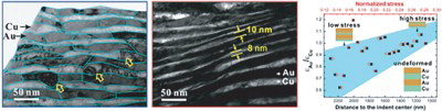
GRAPHICAL ABSTRACT
IMPACT STATEMENT
An abnormal phenomenon of reduced deformability of Au layers compared to Cu layers in Cu–Au NLCs gradually disappeared as the constituent layer thicknesses were thinned plastically to less than 10 nm.
Introduction
Different combinations of materials with a large difference in physical properties can be used to produce ultrastrong nanolayered composites (NLCs) [Citation1], such as metal–ceramics, metal–amorphous alloy, and metal–metal. Mismatches of physical properties between two layer constituents in NLCs, such as the elastic modulus or lattice parameter, can lead to an extra strengthening effect [Citation1,Citation2], but the ductility of the materials is often reduced due to plastic deformation instability [Citation3,Citation4] or the premature fracture of the hard component [Citation5–7]. Whether the two constituent layers can be continuously and coordinately deformed is an important factor in controlling the ductility of heterogeneous NLCs [Citation8] and nanomaterials [Citation9]. However, the plastic deformation mechanism of the composites at nanoscales is still not fully understood even if the strengthening mechanisms from bulk to nanoscale materials have been well established [Citation10–12].
It has been accepted that the strength of the metallic NLCs strongly depends on the thickness of the constituent layers. When the layer thickness decreases from several hundred nanometers to few nanometers, the activity of dislocations will change from dislocation pile-up at the interface to single dislocation slip in the constrained layer, and finally dislocations crossing the interface [Citation12]. Such a transition of the strengthening mechanisms also indicates that there is a variation of the plastic deformation behavior for different length scales. To unveil plastic deformation behavior of metallic NLCs, a number of investigations have been conducted using different loading modes, such as nano/microindentation [Citation3,Citation13–15], in situ indentation in the transmission electron microscopy (TEM) [Citation16] and scanning electron microscopy (SEM) [Citation17], micropillar compression [Citation18–20], cold rolling [Citation21,Citation22], scratching, and cyclic sliding [Citation23,Citation24]. Shear banding, as a dominant deformation behavior, causes plastic deformation instability of the NLCs [Citation14,Citation20,Citation25,Citation26]. Thus, unstable shear banding limits the deformability of the metallic NLCs, and even induces mixing behavior in NLCs [Citation21,Citation27]. Some ultrastrong NLCs even show a cracking tendency under severe plastic deformation [Citation5,Citation28,Citation29]. Deformation instabilities are related to the localized strain transfer process between the different layers, which depends on the type of interface.
Owing to the difference between the two layer constituents, the lattice mismatch may cause coherency stresses or residual stresses in the different layers [Citation30]. At the semi-coherent and incoherent interfaces, the misfit dislocations release the coherency stress and cause work hardening in the absence of dislocation cell structure formation [Citation31]. In the plastic deformation process of NLCs, the interaction among dislocations in the two constituent layers and the interface may exhibit different behaviors, leading to incompatible deformation. The interface barrier strength for the transmission of a dislocation across the interface varies with the core structure of a dislocation within the interface and the discontinuity of the slip planes [Citation32,Citation33]. Furthermore, the difference in stacking fault energy, which defines the ability of twin formation, may also affect the compatible deformation by twinning/detwinning [Citation34].
In this work, the co-deformation behavior of Cu–Au NLCs subjected to microindentation loading was investigated. The strain analysis for the Cu and Au layers shows an abnormal phenomenon: the softer Au layer was observed to exhibit less deformability compared to the harder Cu layer in the layer thickness range of 10s of nanometers, while the difference in the plastic strain between the constituent layers decreased when the individual layer thickness was further reduced. The possible mechanisms for the observed co-deformation behavior of the nanoscale Cu–Au NCLs will be discussed.
Experimental design
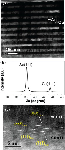
1 µm-thick Cu–Au NLCs with an individual layer thickness of 50 nm were deposited onto 525 µm-thick single crystal Si substrates passivated by a SiNx layer (about 50–320 nm thick) using DC magnetron sputtering. The sputtering deposition was at a rate of 0.3 nm/s with 10−7 Torr vacuum pressure and 0.4 Pa working pressure at 78°C. To minimize oxidation effects, the top surface layer of the NLC consists of Au. Both Au and Cu layers consist of columnar grains with an in-plane size of 79.3 ± 24.5 nm (Figure (a)), and have strong {111} out-of-plane textures, as characterized by X-ray diffraction (XRD) θ-2θ scans in Figure (b). High-resolution transmission electron microscopy (HRTEM) of the Cu–Au interface in Figure (c) reveals that the interface orientation relationship between Cu and Au layers typically follows {111}Cu//{111}Au and <110>Cu//<110>Au. To locally introduce a large plastic deformation in the Cu/Au NLC, microindentation testing was conducted at a load of 0.5N with 5s holding time. Cross-sectional TEM samples of the indented regions were prepared through mechanical grinding and then thinning further by a precision ion polishing system (Gatan 691) at −100°C. Microstructures were examined by a field-emission gun TEM (FEI Tecnai F20) operating at 200 kV.
Figure 1. (a) TEM cross-sectional image of the as-deposited Cu–Au NLCs with individual layer thickness of 50 nm, (b) XRD scans, (c) HRTEM image of interface region in the as-deposited Cu–Au NLCs.
Results and discussion
Figure (a) shows a TEM cross-sectional image of the deformation zones (DZ) of the Cu–Au NLCs beneath an indent. The cross-section was not prepared exactly in the indent center due to the difficulty in exactly locating the indent center during the mechanical grinding and subsequent ion-milling of the TEM sample, but the typical severe DZ close to the indent tip was obtained. Two regions I and II indicated by the blue and red rectangles, respectively, in Figure (a) were carefully characterized. In region I further away from the indent center, shown in Figure (b), columnar grain boundaries and the layer interfaces were outlined by light blue lines. Both the Cu and the Au layers appear thinner and wavy due to non-uniform plastic deformation of some grains. Some dislocation line contrasts were observed, as indicated by arrows in Figure (b). It is worth noting that the Cu layers seem to be thinned more than the Au layers in region I. Figure (c) shows a close observation on deformation region II, which is closer to the indent center than region I. Both the Cu and Au layers were thinned to about 10 nm, and the plastic deformation of each layer tends to be more uniform than that in region I, revealing a better co-deformation behavior. The interface structure in the deformation region was confirmed to be the same as in the as-deposited material (Figure (c)), as characterized by a selected-area electron diffraction pattern shown in Figure (d) and HRTEM observation shown in Figure (e).
Figure 2. (a) TEM cross-sectional images of the indentation-induced deformation region of the 50 nm Cu–Au NLCs, and close observations of (b) region I and (c) region II, (d) selected-area electron diffraction pattern of the deformation region, and (e) HRTEM image of the interface region in the deformation region.
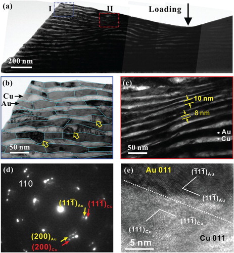
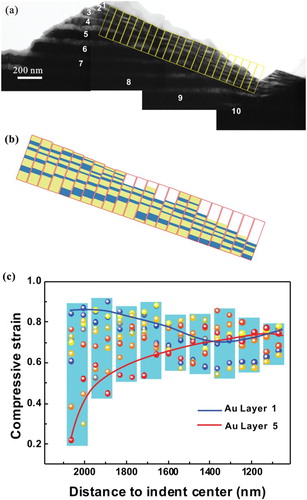
Figure (a) shows another typical TEM cross-sectional image of the indentation-induced plastic DZ in the NLCs beneath the indent, where the cross section almost exactly passed through the indent center. To measure the variation in the layer thickness, the deformation region beneath the indent was subdivided into a set of DZ as shown by the series of yellow rectangles in Figure (a). Each bilayer-period of the film was numbered by 1–10 in a sequence from the top layer to the bottom layer. By measuring the thicknesses of the Cu and Au layers of each bilayer-period in every DZ, we can map the actual thickness of each layer, as shown in Figure (b), where yellow and light blue blocks represent the Au layers and Cu layers, respectively. Based on the difference between the layer thickness before and after deformation, the plastic strain () of each constituent layer along the normal direction (out-of-plane direction) of the layer in different DZs was calculated by
(1)
where λ0 and λ are the individual layer thickness before (Figure (a)) and after (Figure (a)) deformation, respectively. Since the top and the bottom layers could not be distinguished, their strains were not calculated. Figure (c) presents the variation of the normal compressive strain of the Au and Cu layers in each bilayer-period as a function of the DZ distance to the indent center along the layer direction (in-plane direction). The light blue columns in Figure (c) depict the range of variation of the data at a certain distance to the indent center. Overall, the strain of the layers increases with decreasing DZ distance to the indent center. Furthermore, the layers close to the surface of the NLC, such as Au layer 1 was subjected to a larger plastic strain than the layers closer to the substrate, such as Au layer 5, as indicated by the blue and red lines, respectively, in Figure (c). Thus, two strain–stress gradients can be seen, for example, both along the directions parallel and normal to the layers in the NLCs.
Figure 3. (a) TEM cross-sectional image of a typical deformation region beneath the indent of the 50 nm Cu–Au NLCs, (b) schematic illustration of the layer thickness measurement in different DZ based on the TEM cross-sectional observation in (a), (c) compressive strain of each layer along the normal direction of the layers vs. the distance of the DZ to the indent center. The light blue columns show the range of variation of the data points at the different distances to the indent center.
To further evaluate the plastic deformation ability of the Au and Cu layers in the different DZs, we estimated the distribution of the normal compressive stress and shear stress beneath the indent using a 2D linear-elastic finite-element (FE) analysis assuming a plane strain model. The indenter was modeled as a rigid body with a 70.3° semi-apex angle. A 2D linear elastic model is used for both the NLCs and the substrate. The NLC was modeled as several sub-layers that were assigned the material properties of Cu and Au, with Au as the top surface layer. The material properties used in the simulation are listed in Table .
Table 1. Parameters of Au, Cu, and Si used in the FE simulation.
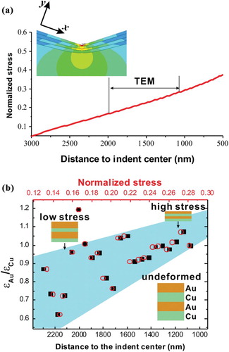
Although the stress values obtained in a purely elastic simulation are unrealistically high, the variation of the stress over the distance from the indent center can be helpful in understanding the microstructural changes we observed. Figure (a) shows that the stress normalized by the maximum in the normal direction (y direction) of the contact surface is nearly linear in the corresponding DZ location studied by TEM (Figure (a)). The inset in Figure (a) shows the FE stress contours of the von Mises stress in the cross section of the NLCs and substrate underneath the microindentation. In order to quantitatively characterize the extent of the co-deformation of the Au and Cu layers in Figure (a), the ratio of the compressive strain () of the two layer types was calculated and plotted in Figure (b). The black solid data points represent the variation of
with the DZ distance to the indenter center. The red open symbols in Figure (b)) correlate the variation of
with the normalized stress determined by the ANSYS. It is found that there is a significant difference in plastic compressive strain between the Au and the Cu layers (
) when the DZ was at a distance of >2100 nm from the indent center, while this difference decreased when the DZ was closer to the indent center. At the same time, the compressive stress increased and the layers were more severely thinned until finally
reached a value of ∼1.0 in the DZ less than about 1400 nm away from the indent center. Since Au has a lower shear modulus [Citation35], stacking fault energy [Citation36,Citation37] and twin boundary energy [Citation34,Citation36] than Cu, the Au layers should be expected to experience more plastic deformation. However, the evaluation of
shows a contrary trend as the Cu layers became much thinner than the Au layers during indentation loading. In what follows, we will discuss the possible origin of this abnormal co-deformation behavior.
Figure 4. (a) Variation of the stress normalized by the maximum in the normal direction of the contact surface estimated by the FEM with DZ distance to the indent center, and (b) compressive strain ratio of the Au layer to the Cu layer () vs. DZ distance to the indent center.
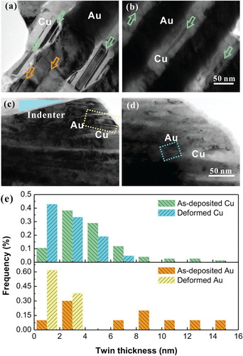
First, one may question whether deformation twinning is one of dominant deformation mechanisms because Au has low stacking fault energy. A comparison of twins is presented in Figure (a,b) for the as-deposited NLCs and in Figure (c,d) for the deformed NLCs, as characterized by TEM. Some growth twins parallel to the interface were found in both the Au (orange arrow) and Cu layers (green arrow) in the as-deposited NLCs. After deformation under microindentation, twins were hardly observed in the layers, which were thinned during indentation to less than 10 nm thickness, whereas twins can still be found within the thicker layers shown in Figure (c,d). Twins that were not parallel to the interface were hardly observed after deformation. For the twins parallel to the interface, Figure (e) indicates that the twin thickness in Cu changes slightly after deformation, while that in Au decreases, indicating the occurrence of detwinning. Yan et al. [Citation34] suggested that detwinning in the Au layers was attributed to the residual compressive stress and the low stacking fault energy of Au. In our study, not only are the twins in both the as-deposited and the deformed Cu–Au NLCs distributed sparsely over the TEM cross sections, but also twinning or detwinning behaviors induced by partial dislocations in Cu–Au NLCs is almost parallel to the interface (perpendicular to the loading direction). Thus, it is expected that deformation involving twinning processes is not the predominant deformation mechanism in Cu–Au NLCs.
Figure 5. TEM cross-sectional view of twins in the Cu–Au NLCs (a) and (b) as-deposited, (c) and (d) deformed; and (e) comparison of frequency of twins with different thicknesses before and after deformation in Cu and Au layers.
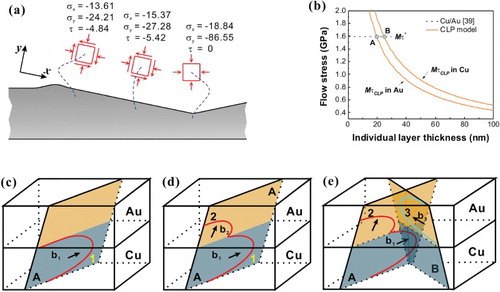
Second, Figure (a) presents the stress state beneath the indent estimated by the FE method. The DZ in Figure (a) is actually subjected to a triaxial compressive stress with a shear stress component corresponding to the middle stress state schematic in Figure (a). To simplify the stress analysis, we only consider the normal compressive stress along the out-of-plane direction (y direction) in the condition of two-dimensional plane strain. According to the linear elastic theory, equals to the strain ratio in the y direction,
(2)
where E is Young’s modulus,
and
are the normal compressive stresses along x and y directions, respectively, and
is Poisson’s ratio. Substituting ECu = 130 GPa, EAu = 78 GPa,
, and
, the theoretical value of
is found to be in the range of 1.41–1.67. However, the experimentally determined
value is less than 1.2. Thus, the elastic theory cannot explain why the Cu layer was subjected to more plastic deformation than the Au layer.
Figure 6. Schematic illustration of (a) stress state in the different zones beneath the indent (stresses given in GPa), (b) variation of flow stress with the individual layer thickness of Cu or Au layers, schematic illustration of (c) initial CLS of dislocations in Cu layers, (d) confined layer glide loop 1 on slip plane A spanning over the Cu layer into the neighboring Au layer to generate dislocation loop 2 on same slip plane A in the Au layer, and (e) interaction between dislocation loop 2 in slip plane A and dislocation loop 3 in slip plane B in the Au layer.
Third, residual stresses in the constituent layers can be generated by a coherency stress due to the lattice mismatch and a thermal stress induced during the film growth. The theoretical (111) plane spacing (a0) of the Cu layer is a0 = 2.0860 Å and that of the Au layer is a0 = 2.3548 Å, while the actual (111) plane spacing (a) was measured by the XRD analysis as aCu = 2.0848 Å and aAu = 2.3573 Å, which reflects the existence of the residual stress. Assuming that the NLCs are in the plane stress state, the strain perpendicular to the film plane can be obtained by
(3)
According to the plane stress–strain analysis in the isotropic material [Citation35], the in-plane residual stress is
(4)
Thus, the in-plane residual stresses in the Au and Cu layers are estimated as −0.118 and 0.227 GPa, respectively. They are lower than the stress introduced by microindentation loading by one order of magnitude. This indicates that the out-of-plane deformation of the Au layer should be suppressed by such in-plane residual compressive stress, and the Cu layer should be deformed more under the in-plane residual tensile stress during indentation. After recalculation of the strain ratio
considering these in-plane residual stresses,
is still more than 1.5 when the stress perpendicular to the film plane is more than 5 GPa. Therefore, the residual stress does not have a significant effect on the strain ratio.
The deformation morphology of the constituent layers in deformation region I far from the indent center (Figure (b)) shows that the Cu–Au NLCs was not deformed uniformly. Some dislocation activities were found in Figure (b) resulting from the activation of dislocations in the nanoscale layers. It has been observed that although the residual stress is low, the source operation of dislocations in the constituent layer with tensile stress may occur when the individual layer thickness is in the range of 10 nm [Citation38]. The Cu layers in Cu–Au NLCs just have in-plane residual tensile stress during indentation, which could favor the dislocation source activation, and consequently the Cu layers would deform more easily than the Au layers. This is the first possible explanation why the Cu layers were subjected to more plastic deformation than the Au layers.
Forth, it is expected that the confined layer slip (CLS) is the main strengthening mechanism when the individual layer thickness is 50 nm. The shear stress for CLS is estimated by [Citation38]
(5)
where G, b, ν and h′ are the shear modulus, the magnitudes of Burgers vectors, Poisson’s ratio and the distance on the slip plane between adjacent interfaces, respectively. The relationship of h′ and the single layer thickness h is
(6)
where φ = 70.5° is the angle between slip plane (111) and the interface, substituting μ, b, ν of Au and Cu with 31 and 48 GPa, 0.288 and 0.256 nm, 0.44 and 0.34, respectively. The flow stresses (σf) of the Au and Cu layers are obtained by τCLS multiplied by a Taylor factor (M) of 3.06. The two solid curves in Figure (b) show the variation of σf with h. The dashed line in Figure (b) shows the peak strength(
), which is determined by the interface barrier strength (τ*) to a single dislocation crossing the interface, that is, τ* = 0.53 GPa for the present Au–Cu NLCs [Citation39]. Two solid curves cross the dashed line, forming two intersection points A and B for the Au and Cu layers. In the process of the indentation-induced thinning of the layers from 50 nm to less than 10 nm, it is expected that there is a transition of the plastic deformation mechanism from CLS to the slip transmission across the interface since the flow stress of the CLS reaches
at points A and B. The length scale corresponding to points A and B indicates that the transition can occur earlier in the Cu layers than in the Au layers. In addition, some barriers to the CLS, for example grain boundaries, may make the mechanism transition happen earlier. This represents another mechanism, which can explain why the Cu layer was subjected to more plastic deformation than the Au layer.
Fourth, the ratio of the dislocation energy (U) in Au to that in Cu can be estimated by [Citation36]
(7)
where the magnitudes of the shear modulus (μAu and μCu) and Burgers vectors (bAu and bCu) are the same as in Equation (5). We can find that UAu/UCu = 0.82, which also indicates that it might be easier for the dislocation to move from the Cu layer into the Au layer than from the Au layer to the Cu layer. This would be the third reason.
Figure (c–e) schematically illustrates the dislocation behaviors in Cu–Au NLCs according to the three processes described above, which are likely to cause the observed differences in plastic deformation behaviors. With compressive deformation induced by indentation, the layer thicknesses continuously decrease causing the change of the predominant deformation mechanisms. In the 50 nm-thick layers, it is expected that the CLS of dislocation loops (dislocation loop 1 in Figure (c)) would occur, preferentially in the Cu layer. The dislocation glide is then stopped by the columnar grain boundary triggering glide loop 1 on slip plane A to span over the Cu layer into the neighboring Au layer to generate dislocation loop 2 on the same slip plane A instead of just moving within the Cu layer as the layers are being thinned (as schematically shown in Figure (d)). The formation of dislocation loop 2, as a product of the dislocation transmission across the interface, leads to the strain transfer from one layer to the other one. In this case, the dislocation 2 on slip plane A may interact with the activated CLS dislocation 3 on slip plane B, and block the CLS in the Au layer, as schematically illustrated in Figure (e). As shown in Figure (b), the transition from the CLS mechanism to slip transmission across the interface occurs earlier in Cu layers than in Au layers; thus the preferential transmission of dislocations from Cu to Au layers may result in hardening of the Au layers due to such an interaction (of dislocation loops 2 and 3 in Figure (e)). This kind of strain hardening in the Au layer may lead to the abnormal decrease in under the initial stage of indentation loading.
With further loading, as the layer thickness was thinned down to about 10 nm or less, as observed in Figure (e), the morphology of the Cu and Au layers exhibits more uniform co-deformation and is about 1.0 (Figure (b)). For even thinner layers, when the range of a few nanometers is reached, the CLS of the dislocation loops becomes increasingly difficult and the transmission of dislocations across the interface takes over, becoming the predominant plastic deformation mechanism [Citation12]. Thus, the co-deformation behavior and the strain transfer fully depend on the activity of dislocations crossing the interface. In this case, the uniform co-deformation in Cu–Au NLCs may happen through the shear stress-driven refreshing capability of plastic deformation under indentation loading [Citation40].
Conclusion
The co-deformation behaviors of 50 nm Cu–Au NLCs were investigated by indentation loading combined with careful TEM characterizations. Our results reveal an abnormal co-deformation behavior. The Cu layers experienced more out-of-plane compressive strain than the Au layers during the initial stage of plastic deformation, while such a difference in the compressive strain between the Cu and the Au layers gradually decreased, as the layers were heavily thinned down to about 10 nm or less. Three mechanisms causing this unexpected behavior are conceivable: (i) The residual tensile stress in the Cu layers, (ii) the larger critical length scale for the transition from the CLS to the interface transmission, and (iii) the higher dislocation energy of Cu would make it easier for dislocations to cross the interface from the Cu layers to the Au layers. These crossing dislocations block the CLS in the Au layers, leading to an additional hardening of the Au layers. With further decrease in the layer thickness down to only few nanometers during deformation, the deformation mechanism of the Cu–Au NLCs may change to relatively uniform co-deformation through dislocation crossing-induced strain transfer.
Disclosure statement
No potential conflict of interest was reported by the authors.
Additional information
Funding
References
- Koehler JS. Attempt to design a strong solid. Phys Rev B. 1970;2:547–551. doi: 10.1103/PhysRevB.2.547
- Rao S, Hazzledine P, Dimiduk D. Interfacial strengthening in semi-coherent metallic multilayers. MRS proceedings; Cambridge Univ Press; 1994. p. 67.
- Li YP, Zhu XF, Zhang GP, et al. Investigation of deformation instability of Au/Cu multilayers by indentation. Philos Mag. 2010;90:3049–3067. doi: 10.1080/14786431003776802
- Li YP, Zhu XF, Tan J, et al. Comparative investigation of strength and plastic instability in Cu/Au and Cu/Cr multilayers by indentation. J Mater Res. 2009;24:728–735. doi: 10.1557/jmr.2009.0092
- Yan JW, Zhu XF, Zhang GP, et al. Evaluation of plastic deformation ability of Cu/Ni/W metallic multilayers. Thin Solid Films. 2013;527:227–231. doi: 10.1016/j.tsf.2012.11.052
- Zhang JY, Zhang X, Liu G, et al. Dominant factor controlling the fracture mode in nanostructured Cu/Cr multilayer films. Mater Sci Eng A. 2011;528:2982–2987. doi: 10.1016/j.msea.2010.12.054
- Mara NA, Li N, Misra A, et al. Interface-driven plasticity in metal–ceramic nanolayered composites: direct validation of multiscale deformation modeling via in situ indentation in TEM. JOM. 2016;68:143–150. doi: 10.1007/s11837-015-1542-1
- Ashby M. The deformation of plastically non-homogeneous materials. Philos Mag. 1970;21:399–424. doi: 10.1080/14786437008238426
- Utyashev FZ. Strain compatibility and nanostructuring of bulk metallic materials via severe plastic deformation. Mater Sci Forum: Trans Tech Publ; 2010. p. 45–9.
- Greer JR, De Hosson JTM. Plasticity in small-sized metallic systems: intrinsic versus extrinsic size effect. Prog Mater Sci. 2011;56:654–724. doi: 10.1016/j.pmatsci.2011.01.005
- Arzt E. Overview no. 130—size effects in materials due to microstructural and dimensional constraints: a comparative review. Acta Mater. 1998;46:5611–26. doi: 10.1016/S1359-6454(98)00231-6
- Misra A, Hirth JP, Hoagland RG. Length-scale-dependent deformation mechanisms in incoherent metallic multilayered composites. Acta Mater. 2005;53:4817–24. doi: 10.1016/j.actamat.2005.06.025
- Wang F, Huang P, Xu M, et al. Shear banding deformation in Cu/Ta nano-multilayers. Mater Sci Eng A. 2011;528:7290–4. doi: 10.1016/j.msea.2011.06.019
- Zhang GP, Liu Y, Wang W, et al. Experimental evidence of plastic deformation instability in nanoscale Au/Cu multilayers. Appl Phys Lett. 2006;88:013105. doi: 10.1063/1.2159581
- Li YP, Zhu XF, Tan J, et al. Two different types of shear-deformation behaviour in Au-Cu multilayers. Phil Mag Lett. 2009;89:66–74. doi: 10.1080/09500830802613147
- Li N, Wang J, Misra A, et al. Direct observations of confined layer slip in Cu/Nb multilayers. Microsc Microanal. 2012;18:1155–1162. doi: 10.1017/S143192761200133X
- Rzepiejewska-Malyska K, Parlinska-Wojtan M, Wasmer K, et al. In-situ SEM indentation studies of the deformation mechanisms in TiN, CrN and TiN/CrN. Micron. 2009;40:22–27. doi: 10.1016/j.micron.2008.02.013
- Mara NA, Beyerlein IJ. Review: effect of bimetal interface structure on the mechanical behavior of Cu–Nb fcc–bcc nanolayered composites. J Mater Sci. 2014;49:6497–516. doi: 10.1007/s10853-014-8342-9
- Zhang JY, Liu G, Sun J. Comparisons between homogeneous boundaries and heterophase interfaces in plastic deformation: nanostructured Cu micropillars vs. nanolayered Cu-based micropillars. Acta Mater. 2013;61:6868–6681. doi: 10.1016/j.actamat.2013.07.065
- Knorr I, Cordero NM, Lilleodden ET, et al. Mechanical behavior of nanoscale Cu/PdSi multilayers. Acta Mater. 2013;61:4984–4995. doi: 10.1016/j.actamat.2013.04.047
- Wang Z, Perepezko JH, Larson D, et al. Mixing behaviors in Cu/Ni and Ni/V multilayers induced by cold rolling. J Alloys Compd. 2015;643:S246–S249. doi: 10.1016/j.jallcom.2014.11.106
- Anderson PM, Bingert JF, Misra A, et al. Rolling textures in nanoscale Cu/Nb multilayers. Acta Mater. 2003;51:6059–75. doi: 10.1016/S1359-6454(03)00428-2
- Ghosh SK, Limaye PK, Swain BP, et al. Tribological behaviour and residual stress of electrodeposited Ni/Cu multilayer films on stainless steel substrate. Surf Coat Technol. 2007;201:4609–4618. doi: 10.1016/j.surfcoat.2006.09.314
- Luo ZP, Zhang GP, Schwaiger R. Microstructural vortex formation during cyclic sliding of Cu/Au multilayers. Scr Mater. 2015;107:67–70. doi: 10.1016/j.scriptamat.2015.05.022
- Mara NA, Bhattacharyya D, Hirth JP, et al. Mechanism for shear banding in nanolayered composites. Appl Phys Lett. 2010;97:021909. doi: 10.1063/1.3458000
- Li YP, Zhu XF, Tan J, et al. Comparative investigation of strength and plastic instability in Cu/Au and Cu/Cr multilayers by indentation. J Mater Res. 2011;24:728–735. doi: 10.1557/jmr.2009.0092
- Guo W, Jägle EA, Choi P-P, et al. Shear-induced mixing governs codeformation of crystalline-amorphous nanolaminates. Phys Rev Lett. 2014;113:035501. doi: 10.1103/PhysRevLett.113.035501
- Misra A, Kung H, Hammon D, et al. Damage mechanisms in nanolayered metallic composites. Int J Damage Mech. 2003;12:365–376. doi: 10.1177/105678903036227
- Zhu XF, Zhang GP, Yan C, et al. Scale-dependent fracture mode in Cu–Ni laminate composites. Philos Mag Lett. 2010;90:413–421. doi: 10.1080/09500831003745241
- Mirkarimi P, Barnett S, Hubbard KM, et al. Structure and mechanical properties of epitaxial TiN/V0. 3Nb0. 7N (100) superlattices. J Mater Res. 1994;9:1456–1467. doi: 10.1557/JMR.1994.1456
- Misra A, Zhang X, Hammon D, et al. Work hardening in rolled nanolayered metallic composites. Acta Mater. 2005;53:221–226. doi: 10.1016/j.actamat.2004.09.018
- Rao SI, Hazzledine PM. Atomistic simulations of dislocation–interface interactions in the Cu-Ni multilayer system. Philo Mag A. 2000;80:2011–2040. doi: 10.1080/01418610008212148
- Wang J, Misra A, Hoagland RG, et al. Slip transmission across fcc/bcc interfaces with varying interface shear strengths. Acta Mater. 2012;60:1503–1513. doi: 10.1016/j.actamat.2011.11.047
- Yan JW, Zhang GP. Revealing the tunable twinning/ detwinning behavior in 25 nm Cu/Au multilayers. Appl Phys Lett. 2013;102:211905. doi: 10.1063/1.4808036
- Meyers MA, Chawla KK. Mechanical behavior of materials. Cambridge: Cambridge University Press; 2009.
- Hirth J, Lothe J. Thoery of dislocations. 2nd ed. New York: John Wiley; 1982.
- Venables J. The electron microscopy of deformation twinning. J Phys Chem Solids. 1964;25:685–692. doi: 10.1016/0022-3697(64)90177-5
- Anderson P, Foecke T, Hazzledine P. Dislocation-based deformation mechanisms in metallic nanolaminates. MRS Bull. 1999;24:27–33. doi: 10.1557/S0883769400051514
- Li YP, Zhang GP. On plasticity and fracture of nanostructured Cu/X (X=Au, Cr) multilayers: the effects of length scale and interface/boundary. Acta Mater. 2010;58:3877–3887. doi: 10.1016/j.actamat.2010.03.042
- Yan JW, Zhu XF, Yang B, et al. Shear stress-driven refreshing capability of plastic deformation in nanolayered metals. Phys Rev Letts. 2013;110:155502. doi: 10.1103/PhysRevLett.110.155502