
ABSTRACT
It is shown by finite element modeling that under high-pressure torsion of water-atomized pure iron powder a zone with high shear strain and high density develops first in a layer adjacent to the moving anvil. The finite element simulation results and an analytical calculation using the minimum plastic energy extremum principle both show that with further deformation the compacted zone extends progressively in the radial and axial directions throughout the specimen.
GRAPHICAL ABSTRACT
IMPACT STATEMENT
The strain non-uniformities that appear during compaction of a metallic powder by high pressure torsion can be properly modeled and the results can be used for material processing.
Introduction
High-pressure torsion (HPT) is an effective severe plastic deformation (SPD) process for producing materials with exceptionally small grain sizes (∼100 nm), and also for consolidating powder materials [Citation1]. Grain refinement also occurs when powders are processed by HPT.
The majority of HPT studies are conducted on solid materials. However, there are obvious advantages of the HPT-assisted powder compaction for fabricating new materials. This technology not only provides efficient powder consolidation—even for hard-to-deform powders—but it also promotes the formation of strong contacts between particles, causes intensive mass transfer in materials that deform, activates phase transformations and chemical reactions [Citation2]. These advantages recently generated a number of studies on HPT of powder materials (see, e.g. [Citation3,Citation4]).
The strain and porosity distributions in the volume of the specimen are very important for powder consolidation because these parameters determine the properties of the obtained materials. So far, this topic is quite scarcely studied. Experimental results on HPT consolidated water-atomized commercially pure iron powder were presented in Refs. [Citation5,Citation6]. In [Citation5] it was reported that the porosity of the iron metallic powder saturates at about 3% under uniaxial compression. Torsion under axial pressure leads to further porosity reduction, up to tenths of a percent. In [Citation6] it was shown that there is considerable strain heterogeneity in the axial direction of an HPT consolidated powder.
Mathematical modeling, employing, in particular, the finite-element technique, can provide useful information on HPT processing. Strain-induced phase transformations under compression and torsion in rotational diamond anvils were simulated using a finite-element approach in [Citation7,Citation8]. Significant heterogeneity was found and strong shear strain localization near the contact surface between the sample and the anvil was quantified. The effects of the elastic deformation of the anvil and the sample on the process were studied in [Citation9]. The effect of friction, the thickness-to-diameter ratio of the specimen, and the rheology of the material on the stress–strain state of the sample during semi-constrained HPT were examined in [Citation10,Citation11]. The results showed that there is a tendency for flow localization during processing and this becomes more obvious during the processing of perfectly plastic or flow-softening materials or when processing samples having high thickness-to-diameter ratios. The analysis demonstrates the effects of the material condition, the disk aspect ratio, and the friction between the disks and the anvil walls. It has been shown that strain is non-uniform, not only in the radial but also in the axial direction of the sample. Extreme strain heterogeneity was reported in [Citation12] where even a dead metal zone was found.
The elastic-plastic and rigid-plastic models are usually used for stress–strain state calculation in HPT. For example, the dislocation cell-based rigid-plastic model presented in [Citation13] was used in [Citation14]. A micro–macro-mechanical material model was employed in [Citation15] for HPT simulations. None of the above-mentioned models allow investigating the evolution of the porosity during HPT of a powder material. The model in [Citation7,Citation8] takes into account the phase transformation with volume reduction, but the physical mechanism of volume change during the phase transformation is different from the one during shear of powders under pressure.
In HPT powder compaction, one has to take care about fully constraining the powder sample [Citation1]. Unfortunately, all the above studies were done in unconstrained or semi-constrained conditions.
In this paper, we model the HPT of already pre-compacted powder specimens under fully constrained conditions; see previous publications of our group in [Citation5,Citation6]. For the simulation of the porosity distribution, we employ the model of [Citation16]. Its main feature is that it takes into account the reduction of voids as well as the formation of new ones. The results show that by increasing the rotation angle of the anvil, the frontier of a high density area is spreading throughout the specimen. It starts from the edge of the rotating piston and moves in both radial and axial directions in the sample volume. We borrowed two model parameters from [Citation16] for modeling the experimental results obtained in our group [Citation5,Citation6]. Good correspondence between theory and experiments was obtained concerning the strain and porosity distributions in the sample.
Modeling conditions
Several rheological models can be used in the finite-element method for the simulation of plastic deformation of powder materials (see a review in [Citation17]. The most commonly used are the modified Drucker–Prager model (see e.g. [Citation18]) and the Shima—Oyane model [Citation19] that are available in the ABAQUS and DEFORM software. In the present work, we apply the Beygelzimer model (see [Citation16,Citation20,Citation21]), which combines the features of the Drucker–Prager model and the Shima-Oyane model. This model takes into account the reduction of voids as well as the formation of new ones. The basic equations of the model are the following (see e.g. [Citation16]):
(1)
(2)
(3)
(4)
where
and
are the components of the stress and strain rate tensors,
and
are the hydrostatic stress and the volume strain rate, respectively, while
and
denote the square root of the second invariant of the deviatoric stress and strain rate tensors, respectively;
is the porosity;
is the generalized cohesion parameter and
is the generalized internal friction parameter from the Drucker–Prager model;
,
,
are the generalized parameters from the Shima–Oyane model. The technique to determine the parameters of the Beygelzimer model is presented in [Citation16,Citation21].
According the Beygelzimer model, the parameter describes the structural ability of the material elements to accommodate each other. In the case when a complete accommodation of the elements is possible: α = 0. The value of α increases with the increase of difficulties to accommodate the plastic deformation. That is, the smaller the capacity of strain accommodation is, the higher the α is.
According to Zhao et al. [Citation5], the porosity of pre-compacted pure iron powder was close to 3% before starting the rotation of the anvil. Torsion under pressure leads to a further reduction of the porosity. Therefore, the relative change in volume cannot be more than 0.03. Such a low porosity has a very small effect on the flow stress and the stress–strain state if there is no instability. Instabilities were not examined in our study. For this reason, the calculation of the stress–strain state of the sample was done using the approximation of a rigid-plastic incompressible body. The porosity was determined from the kinetic equation of the stress–strain state.
For materials with a low porosity and for compact materials, the value of the is in the order of 0.01–0.001,
is in the order of 0.1–0.01, and
, where
is the flow stress of the basic material (see e.g. [Citation16]). Considering this, when
, one can obtain from Equations (1) to (4), in the first approximation, the following equation system:
(5)
(6)
(7)
where
is the strain rate and
is the true strain (von Mises strain).
The kinetic equation (6) is similar to the Shima–Oyane model [Citation22] for the case when , however, it differs from it by the term
on the right-hand side. This term is very important for HPT modeling because it take into account the formation of new pores during large shear strain.
According to Equations (5) and (7), one can find the stress–strain state of the specimen using the von Mises model for rigid-plastic incompressible materials (see, e.g. [Citation23]). After that, the porosity of the material can be obtained by solving the kinetic equation (Equation (6)). This is, however, not possible when there is a loss of stability of the material because of the formation of shear bands (see e.g. [Citation16,Citation21]). We do not consider these regimes in this work.
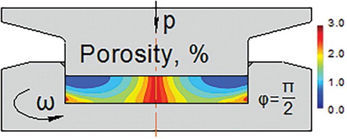
The above-presented problem was solved by the finite element methods using the commercial software package DEFORM-2D/3D, V11.0 [Citation24]. shows the schematic geometry of the constrained HPT process.
Figure 1. Schematic geometry of the constrained HPT process for powder consolidation.
We have carried out a simulation of the HPT consolidation process according to the experimental conditions of our recent experiments published in [Citation5,Citation6]. The geometrical parameters of the simulations were the following: ,
. According to Beigelzimer et al. [Citation16], the
and a parameters for pure iron can be taken as
and
. The stress–strain curve obtained in our experiments [Citation6] during the compaction of pure iron powder was built-in into the FE code (). The boundary conditions on the anvils were considered as perfect adherence of the powder to the flat contact surfaces, and the Tresca-type friction law
was used on the cylindrical surfaces (where
is the friction coefficient; the value of
was 0.25). Additionally, we suppose that there is no outward material flow during constrained HPT (see ). For this reason, the height of the specimen is not reduced during HPT. Under these conditions, a 2D axisymmetric torsion configuration could be used for the numerical calculations in the DEFORM software. The number of initial meshes of the workpiece was 10,000, which was sufficient to explore the local deformation behavior. There was no need to update the mesh in the DEFORM software because the mesh remained undistorted during the use of the 2D axisymmetric torsion model in DEFORM. The upper anvil was rotated at an angular speed of 0.1 rad/s up to two turns under a constant pressure of p = 1.1 GPa.
Figure 2. Stress–strain curve obtained in our group [Citation3] for compaction of pure iron powder.
![Figure 2. Stress–strain curve obtained in our group [Citation3] for compaction of pure iron powder.](/cms/asset/d7050940-603d-473c-b925-2852d46cb412/tmrl_a_1241318_f0002_c.jpg)
The porosity distribution was calculated using Equation (6) in 1000 nodes of the uniformly distributed square mesh. The results were examined in the axial cross-section of the specimen. The average porosity of the sample was calculated by the formula:
(8)
Results and discussion
The true strain distribution in the axial cross-section of the sample is shown in . This figure shows that the HPT powder compaction process presents strong strain heterogeneities, not only in the radial direction, but also in the axial one. This result is in good agreement with our experiments [Citation6]. For quantitative comparison, the calculated shear strain distribution at a distance of 9.61 mm from the axis of the sample after a rotation angle of π/2 is compared with the experimental one (see ). The discrepancy between experimental and theoretical strain near the top of the specimen (when z is small) may be due to (i) a large experimental error in the strain in this area (see Ref. [Citation6]) and (ii) the slippage at the contact surface of the anvil.
Figure 3. The true strain (a), the porosity (b), and the strain rate (c) distributions in the axial cross-section of the sample under a compression pressure of p = 1.1 GPa for increasing rotation angles π/4, π/2, 2π, and 4π, obtained by simulation.
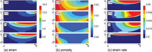
Figure 4. The simulated and experimental true strain distributions (see our previous work [Citation6]) during HPT compaction of iron powder at a distance of 9.61 mm from the sample axis after a rotation of π/2.
![Figure 4. The simulated and experimental true strain distributions (see our previous work [Citation6]) during HPT compaction of iron powder at a distance of 9.61 mm from the sample axis after a rotation of π/2.](/cms/asset/0c275aa8-b149-4edf-95e3-704f94ea2edb/tmrl_a_1241318_f0004_c.jpg)
In order to examine the movement of the compacted powder zone, we take the true strain of 1.0 as a nominal value to define the border of a zone with large plastic deformation. Assuming proportional radial dependence of the shear strain, the true strain is defined for HPT by the following equation:
(9)
where β is the rotation angle of the anvil and r is the distance from the z-axis (see ). shows that this border moves in both the radial and axial directions with increasing rotation angle. Thus, the borderline depends on both r and z, meaning that Equation (9) is not valid for powder processing by HPT. It is not even valid for the r-dependence on the top surface of the disk where the
borderline should be at the radial positions of 6.61, 3.31, and 0.83 mm for the rotation angles of π/4, π/2, and 2π, while in the simulation it is at 5.5, 3.0, and 1.0 mm, respectively (see data in , at z = 0).
Figure 5. The movement of the border zone (defined by a true strain of 1.0) during large plastic deformation of pure iron powder by HPT as a function of the imposed rotation angle of the upper anvil.
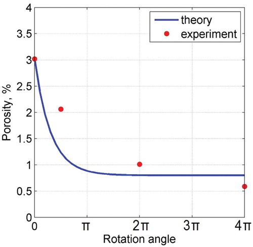
The model predicts a decrease in the average porosity with saturation at a level larger than zero. This is in quite good agreement with the experiment (see ). Note that the use of the non-modified kinetic equation of Ref. [Citation22], which does not account for the appearance of porosity at large shear strain, leads to a very rapid decrease of the porosity. This is inconsistent with the experiments.
Figure 6. The average porosity after different anvil rotation angles.
In the following, it will be shown that the movement of the border in the axial direction follows from the extremum principles of the theory of plasticity. Due to a small change in volumetric strain in comparison with deviatoric strain, it is possible to use the principle of minimum properties of an actual velocity field for incompressible material (see, e.g. [Citation23]). According to this principle, the actual velocity field belongs to the minimum of the functional of the power dissipation of all admissible fields, which can be written for the present case as follows:
(10)
Here the first integral is taken over the volume of the deformable body and the second is on the surface of its contact with the tool where there is friction between the deformable material and the tool.
is a kinematically admissible velocity field,
is its projection onto the surface
,
is the friction stress and
is the von Mises strain rate corresponding to the kinematically admissible velocity field. The kinematically admissible velocity field must satisfy the boundary conditions for the velocity and also the incompressibility condition defined by
(see, e.g. [Citation23]). Therefore, it can be taken in the form:
(11)
where
is the unit vector in the direction of the tangential
axis of the cylindrical coordinate system
(see ),
is the rotation rate of the upper anvil and
is an arbitrary smooth function of z, satisfying the boundary conditions:
(12)
One can verify by direct calculation that the velocity field defined by Equation (11) satisfies the condition of incompressibility . The boundary conditions in Equation (12) express the condition that the material is sticking to the flat upper surface of the anvil and that there is only a tangential velocity component on the cylindrical surface at
. When
, we obtain the velocity field usually used for HPT. We generalize the expression of
by defining
(13)
where
is a parameter. In the following, we will find out the value of
using the principle of minimum properties of an actual velocity field described above. For this purpose, we introduce the following dimensionless variables:
(14)
Here is the flow stress of the material at the start of the rotation of the anvil. One can then show that the strain rate for the kinematically admissible velocity field has the form:
(15)
The projection of the velocity to the surface is given by
(16)
One can rewrite then Equation (10) by using Equations (14)–(16) and the Tresca-type friction law :
(17)
At the start of the rotation of the anvil, the flow stress of the material is , therefore
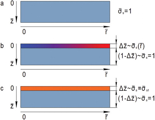
throughout the volume of the sample (see (a)).
Figure 7. One half of the axial section of the specimen: (a) before HPT, (b) nonuniform hardened layer after rotation at a small angle Δβ, and (c) approximation by a thin uniform hardened layer with
.
One can get from Equation (17) for the start of the rotation of the anvil:
(18)
By increasing , the right-hand side of this ratio decreases monotonically, approaching to
when
. The dependence of the function
on z when
(for
) is shown in .
Figure 8. The function for different values of the index k. The case k = 1 corresponds to the velocity field usually used for HPT, for uniform strain distribution along the axial direction.
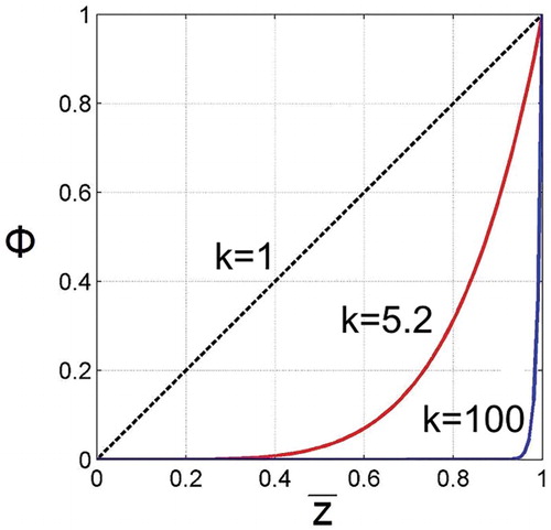
It is clear from that only a thin material layer with a thickness of adjacent to the upper anvil is mainly deformed at the start of the rotation of the upper anvil. Plastic deformation leads to a nonuniform strain hardened layer ((b)). We represent it as a homogeneous layer with an average flow stress of
((c)). The integrals over z in Equation (17) were done in two steps; over a segment
, then over a segment
. In this case, one can obtain from Equation (17):
(19)
For the case when , this relation reads:
(20)
The minimum of is defined by the condition:
(21)
leading to
(22)
When hardening is weak, , thus
. In this case, the velocity field becomes very heterogeneous and the deformation remains localized in the top thin layer. If the material hardens rapidly, the value of
is reducing according to Equation (22). For example, when
and
(the values of other parameters in Equation (22) are given above), one can get from Equation (22):
. For this case, the
function is displayed in . One can see that for this value of k, the non-uniform torsion covers almost half of the height of the sample. Thus, the formation of a thin layer of the hardened material leads to the spread of the plastic deformation along the axial direction of the sample. Moreover, the strain rate in the hardened layer adjacent to the rotating anvil is significantly reduced.
As can be seen in , the flow stress of the material is saturated at large strains. Therefore, at large strains, the flow stress becomes nearly uniform within the sample volume. This effect begins in the upper layer, where the strain is the largest. It is well known that low hardening rate can lead to strain localization. For these reasons, both at small and at high rotation angles, the deformation is localized (see ). One can see that only a thin material layer adjacent to the upper anvil is strongly deformed at the start of the rotation, followed by plastic deformation in the whole volume, finally, at large rotation angles, the deformation localizes again in the upper layer of the specimen.
The above-discussed development of the plastic deformation in constrained HPT testing follows from the principle of minimum power dissipation. Since this analysis is based on the von Mises model, the obtained results are valid not only for low porous materials but for bulk materials too.
Conclusions
By employing the Beygelzimer model of a structurally inhomogeneous porous body (see [Citation16,Citation20,Citation21]) in the commercial DEFORM-2D/3D V11.0 finite element software, it is shown in this paper that the strain under constrained HPT is non-uniform in both the radial and axial directions. For initially homogeneous samples, the deformation is concentrated in a thin layer adjacent to the rotating anvil when rotation starts. If the material does not display strain hardening, the deformation remains localized in a thin layer during further rotation. In contrast, if the material is strain hardening, the plastic deformation penetrates into the sample progressively as a function of the rotation of the anvil. The border of the plastic zone with large strain moves in both the radial and axial directions by increasing the angle of the anvil rotation. The obtained effects are valid for both powder and bulk materials. These effects are associated with the friction on the lateral surface of the sample with the anvil and follow from the principle of minimum power dissipation.
The mathematical simulation predicts a decrease in the average porosity with saturation at a level more than zero. This is in quite good agreement with our experiments recently published in [Citation6].
Disclosure statement
No potential conflict of interest was reported by the authors.
Additional information
Funding
References
- Zhilyaev AP, Langdon TG. Using high-pressure torsion for metal processing: fundamentals and applications. Prog Mater Sci. 2008;53(6):893–979. doi: 10.1016/j.pmatsci.2008.03.002
- Beygelzimer Y, Estrin Y, Kulagin R. Synthesis of hybrid materials by severe plastic deformation: a new paradigm of SPD processing. Adv Eng Mater. 2015;17(12):1853–1861. doi: 10.1002/adem.201500083
- Borchers C, Garve C, Tiegel M, et al. Nanocrystalline steel obtained by mechanical alloying of iron and graphite subsequently compacted by high-pressure torsion. Acta Mater. 2015;97:207–215. doi: 10.1016/j.actamat.2015.06.049
- Bachmaier A, Pippan R. Generation of metallic nanocomposites by severe plastic deformation. Int Mater Rev. 2013;58(1):41–62. doi: 10.1179/1743280412Y.0000000003
- Zhao Y, Massion R, Toth LS, et al. Contribution of shear deformation to grain refinement and densification of iron powder consolidated by high pressure torsion. IOP Conf Series Mat Sci Eng. 2014;63:012032. doi: 10.1088/1757-899X/63/1/012032
- Zhao Y, Massion R, Grosdidier T, et al. Gradient structure in high pressure torsion compacted iron powder. Adv Eng Mater. 2015;17(12):1748–1753. doi: 10.1002/adem.201500012
- Levitas VI, Zarechnyy OM. Numerical study of stress and plastic strain evolution under compression and shear of a sample in a rotational anvil cell. High Pressure Res. 2010;30(4):653–669. doi: 10.1080/08957959.2010.534990
- Levitas VI, Zarechnyy OM. Modeling and simulation of strain-induced phase transformations under compression and torsion in a rotational diamond anvil cell. Phys Rev B. 2010;82:174124. doi: 10.1103/PhysRevB.82.174124
- Kim HS. Finite element analysis of high pressure torsion processing. J Mater Process Technol. 2001;113(1):617–621. doi: 10.1016/S0924-0136(01)00709-9
- Figueiredo RB, Aguilar MTP, Cetlin PR, et al. Analysis of plastic flow during high-pressure torsion. J Mater Sci. 2012;47(22):7807–7814. doi: 10.1007/s10853-012-6506-z
- Kawasaki M, Figueiredo RB, Langdon TG. Twenty-five years of severe plastic deformation: recent developments in evaluating the degree of homogeneity through the thickness of disks processed by high-pressure torsion. J Mater Sci. 2012;47(22):7719–7725. doi: 10.1007/s10853-012-6507-y
- Lee DJ, Yoon EY, Park LJ, et al. The dead metal zone in high-pressure torsion. Scr Mater. 2012;67(4):384–387. doi: 10.1016/j.scriptamat.2012.05.024
- Tóth LS, Molinari A, Estrin Y. Strain hardening at large strains as predicted by dislocation based Polycrystal plasticity model. J Eng Mater Technol. 2002;124(1):71–77. doi: 10.1115/1.1421350
- Yoon SC, Horita Z, Kim HS. Finite element analysis of plastic deformation behavior during high pressure torsion processing. J Mater Process Technol. 2008;201(1):32–36. doi: 10.1016/j.jmatprotec.2007.11.204
- Larijani N, Kammerhofer C, Ekh M. Simulation of high pressure torsion tests of pearlitic steel. J Mater Process Technol. 2015;223:337–343. doi: 10.1016/j.jmatprotec.2015.04.018
- Beigelzimer JE, Efros BM, Varyukhin VN, et al. Continuum model of the structural-inhomogeneous porous body and its application for the study of stability and viscous fracture of materials deformed under pressure. Eng Fract Mech. 1994;48(5):629–640. doi: 10.1016/0013-7944(94)90170-8
- Cocks ACF, Sinka IC. Constitutive modelling of powder compaction – I. Theoretical concepts. Mech Mater. 2007;39(4):392–403. doi: 10.1016/j.mechmat.2006.09.003
- Resende L, Martin JB. Formulation of Drucker–Prager cap model. J Eng Mech. 1985;111(7):855–881. doi: 10.1061/(ASCE)0733-9399(1985)111:7(855)
- Shima S, Oyane M. Plasticity theory for porous metals. Int J Mech Sci. 1976;18(6):285–291. doi: 10.1016/0020-7403(76)90030-8
- Beigel’zimer YE. Plastic deformation of porous solids at low porosity. Sov Powder Metall Met Ceram. 1987;26(3):193–195. doi: 10.1007/BF00797013
- Beygelzimer Y, Varyukhin V, Efros B. Physical mechanics of hydrostatic treatment of materials. Donetsk: DonFTI NANU; 2000 (in Russian).
- Oyane, M, Shima, S, Tabata, T. Consideration of basic equations, and their application in the forming of metal powders and porous metals. Rev J Mech Work Technol. 1978;1:325–341. doi: 10.1016/0378-3804(78)90036-0
- Kachanov LM. Foundations of the theory of plasticity. Amsterdam/London: North-Holland Publishing Company; 1971.
- DEFORM v11.0. Scientific forming technologies corporation.