
ABSTRACT
A gradient nanostructured (GNS) surface layer was generated on an ultrahigh strength bearing steel (AISI 52100) by surface mechanical rolling treatment (SMRT). The initial martensite plates with cementite and retained austenite were transformed into nanograined martensite with a mean size of ∼24 nm at the topmost surface. Axial tension–compression fatigue tests showed that an enhanced fatigue property was achieved on the GNS sample due to the suppressed fatigue crack initiation at the surface. Effects from hardness, microstructure, and residual stress in the GNS surface layer were discussed in relation with the fatigue mechanism of the SMRT sample.
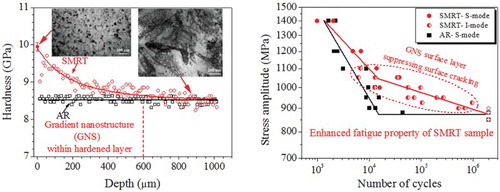
GRAPHICAL ABSTRACT
IMPACT STATEMENT
A gradient nanostructured surface layer was generated on an ultrahigh strength bearing steel, and significantly improved the fatigue property of the steel by suppressing surface crack initiation at lower stresses.
Introduction
Increasing strength is generally applied to improve the fatigue properties of steels. However, the fatigue ratio (fatigue limit relative to tensile strength) becomes smaller as the tensile strength exceeds 1200 MPa, and even lower fatigue strength might be obtained with increasing tensile strength above 1600 MPa (e.g. in bearing steels). This originates from the presence of inclusions and other defects that might act as micro-notches generating fatigue cracks in high-strength materials with high notch sensitivities [Citation1–4].
Fatigue failures are sensitive to the structure and properties of a material’s surface, and the formation of a nanostructured surface layer with higher strength, that is, surface nanocrystallization [Citation5,Citation6], is able to enhance fatigue properties of metals. With such techniques as surface mechanical attrition treatment (SMAT) and surface mechanical grinding treatment [Citation7–9], a gradient nanostructured (GNS) surface layer has been produced on various metals, in which the mean grain size is in the nanometer scale at the topmost surface and gradually increases to submicron and micron scales with increasing depth. Remarkably enhanced fatigue properties have been observed on pure Cu [Citation10], Ni-based Hastelloy [Citation11], and 316L stainless steel [Citation12] with GNS layers. Furthermore, it was noticed that the fatigue ratio increases, accompanied with a significantly enhanced strength in a GNS 316L stainless steel [Citation9].
However, previous studies concentrated on the fatigue properties of GNS materials with low or medium strength, while the surface state might play a more important role in the fatigue behavior of materials with high strength due to their larger notch sensitivities [Citation13]. Therefore, forming GNS surface layers on bearing steels is expected to achieve further increased fatigue properties than by increasing strength. In fact, some previous works have studied the fatigue behavior of bearing steels processed by some traditional surface modification approaches, such as shot peening and deep rolling [Citation14–16]. And the results indicated that the fatigue property and fracture mode might be influenced by surface hardening and compressive residual stress. However, the affected layers with distinct hardening are relatively thin (<200 µm) after these treatments, and microstructure details in them have not been characterized. Therefore, the relationship between surface microstructure and fatigue behavior is still unclear in bearing steels. In addition, these fatigue tests were mostly under rotary bending with a high frequency for the concerns of very high cycle fatigue (VHCF, roughly >107 cycles) behavior, while rotary bending and high frequency have been confirmed to affect the experimental results by involving a smaller volume under damaging stresses and elevating sample temperature, respectively [Citation3,Citation17,Citation18].
In the present study, we utilized a newly developed technique, surface mechanical rolling treatment (SMRT), to generate a thick GNS surface layer on an ultrahigh strength bearing steel. Subsequently, the fatigue property of the GNS sample was studied under axial pull–push loading with a low frequency, and effects of the GNS surface layer and residual stress on the fatigue mode were analyzed.
Experimental details
AISI 52100 bearing steel with chemical compositions (in wt%) of 0.97C, 1.55Cr, 0.40Mn, 0.27Si, 0.02Cu, 0.01Ni, and balance Fe was used in this work. The initial material was hot-forged, oil-quenched after austenitization at 845°C for 30 min, and finally tempered at 150°C for 120 min. Fatigue specimens with an hourglass shape (with a minimum diameter of 5 mm and an arc radius of 75 mm) were prepared from the billet, for SMRT processing and for as-received (AR) reference samples.
Detailed descriptions of the SMRT set-up and procedure were reported previously in refs. [Citation9,Citation19]. In brief, the treated sample turned around its axis against a polished WC–Co cermet ball, which was confined (rotatable) on a tool tip. The turning velocity (ν1) of the rod sample was 600 revolutions per minute, the moving velocity (ν2) of the ball along the sample axis was 0.1 mm s−1, and the preset penetration depth (ap) of the ball into the sample surface was 50 µm. The SMRT procedure was repeated 3 times, while the processing parameters ν1 and ν2 were kept the same and ap increased 50 µm each time. Cycling oil was applied to lubricate and cool the ball and the sample during SMRT.
Morphologies of different samples were observed by using scanning electronic microscopy (SEM) on an FEI Nova NanoSEM 430 unit. Detailed microstructures were observed by using transmission electron microscopy (TEM) on a JEOL-2010 unit. Phase constitutions were characterized by using a Rigaku D/max-2400 X-ray diffractometer. Meanwhile, in-depth distributions of residual stress (along the axial direction) in surface layers of different samples were determined by combing X-ray diffraction (XRD) with iterative electrolytic sectioning.
Axial tension–compression fatigue tests were performed at room temperature by using an Instron 8850 electro-hydraulic testing machine. The stress control fatigue behavior was studied with a zero mean stress (R = −1) and a frequency of 15 Hz. The in-depth microhardness distributions were measured on cross-sectional samples before and after fatigue tests by using a Qness Q10 A+ tester.
Formation of the GNS surface layer
The initial microstructure of the AR sample is a typical martensitic structure, in which dispersive cementite particles distribute in the plate-like martensite matrix. TEM observations (see Figure (a)) revealed that dense dislocations exist in the fine martensite plates. And the average size of the carbides is ∼450 nm. In addition, few retained austenite phases co-exist in the quenched and tempered steel (see Figure (b)).
Figure 1. (a) A typical TEM image of the AISI 52100 bearing steel in the quenched and tempered state, and (b) XRD patterns of the samples before and after SMRT. A carbide particle is pointed by an arrow on (a). (c) Bright-field and (d) dark-field TEM images of the topmost surface layer of the SMRT sample. Insert in (c) shows the corresponding SAED pattern, on which (d) is taken from the (110) diffraction. Insert in (d) shows the statistical distribution of grain size.
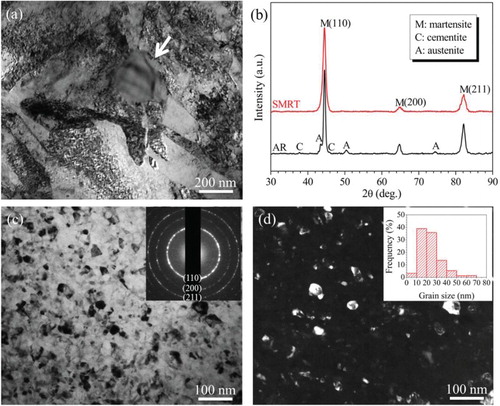
After SMRT, nano-sized grains with random crystallographic orientations have been formed in the topmost surface layer, as shown in Figure (c,d). The grains are nearly equiaxed with a mean size of ∼24 nm. In addition, cementite particles and retained austenite are difficult to observe in the surface layer by using TEM and the corresponding selected area electron diffraction (SAED) pattern. This is also confirmed by XRD analyses in Figure (b).
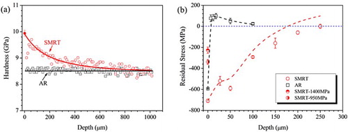
Figure (a) shows that a hardened surface layer of ∼600 µm in thickness has been formed on the SMRT sample. The microhardness reaches a maximum value of ∼9.9 GPa at the treated surface, and gradually decreases to the matrix value (∼8.5 GPa) with increasing depth. In addition, pronounced compressive residual stresses have been introduced in the SMRT surface layer. As shown in Figure (b), the compressive residual stress reaches ∼700 MPa at the topmost surface, and gradually decreases with increasing depth. The total thickness of the surface layer with compressive residual stress is ∼180 µm. In comparison, although a compressive residual stress was introduced at the surface of the AR sample by mechanical grinding, it transformed into a slight tensile state within a very thin (∼5 µm) layer.
Figure 2. In-depth distributions of (a) microhardness and (b) residual stress in the samples before and after SMRT. The solid point in (a) was averaged from values measured at the SMRT surface of a plane-view sample. The dashed lines in (b) show residual stress distributions after modifications by considering the stress redistribution as a result of the removal of a thin surface layer after each step. SMRT-1400 MPa and SMRT-950 MPa denote the SMRT samples after fatigue tests at 1400 and 950 MPa, respectively.
Bearing steels such as 52100 possess ultrahigh strength in quenched and tempered states owing to the fine and C-supersaturated martensite with a high density of dispersive carbides and dislocations. However, their ductility is rather low [Citation18,Citation20], so that it is difficult to further refine their microstructures via plastic deformation, and no work has reported the formation of nanostructured grains in bulk specimens of such steels to the authors’ knowledge. It is clear that grain sizes have been refined into nano-scale in the surface layer of the 52100 steel by SMRT. And the gradient distribution in microhardness along depth corresponds to the gradient distribution of grain sizes in the surface layer, that is, a GNS surface layer has been fabricated in this work.
During the SMRT process, lubrication and cooling were applied and thermal effects were diminished to the most extent. Therefore, the formation of the GNS surface layer is expected to be predominately induced by dislocation activities (i.e. mechanically induced [Citation21]) in the initial martensite structure, similar to the microstructural refinement processes in a P92 ferritic steel by SMAT [Citation22] and a Z5CND16-4 martensitic steel by SMRT [Citation19]. This has also been confirmed by the measured hardness distribution in the SMRT sample: the microhardness increases gradually with decreasing depth (see Figure (a)). And a good agreement was found between the measured data on the SMRT surface and the Hall–Petch plot of microhardness vs. grain size previously reported on the surface of a SMAT 52100 steel [Citation23], on which ferrite/martensite grains with a mean size of ∼8 nm were predominately formed by dislocation activities from a spheroidizing annealed sample. In contrast, the in-depth hardness profile in the SMRT sample is different from the results usually observed in thermally induced white-etching layers formed by such processes as hard turning, grinding, drilling, and under prolonged rolling contact fatigue [Citation18,Citation21,Citation24,Citation25]. Although grain sizes in the order of tens of nanometers might also be obtained in thermally induced white-etching layers, a region with a much lower hardness than in the matrix was usually formed, possibly due to dynamic recrystallization and phase transformation as consequences of dramatic adiabatic deformation heating.
In addition, high strains with high rates result in the refinement/dissolution of carbides and the transformation of retained austenite into martensite in the SMRT surface layer. As demonstrated by Zhou et al. [Citation26] and Hosseini et al. [Citation21], cementite particles might be plastically deformed when the matrix grains were refined to a critical size. Accumulated multiple dislocations gliding progressively refined cementite into nano-sized particles, subsequently led to the dispersion of nano-sized carbides and diffusion-based carbide refinement. Meanwhile, the retained austenite in the initial microstructure might be transformed into martensite due to its mechanical instability, and gradually be refined into nano-sized grains during SMRT. For example, most of the retained austenite in a quenched and tempered 52100 steel was decomposed into martensite at strains below 0.05 [Citation27].
Some traditional surface modification processes might also introduce hardening and compressive residual stress in the surface layer of bearing steel [Citation14,Citation15,Citation28]. As compared in , it is clear that the hardened surface layer in the SMRT sample is much thicker than those formed by traditional processes. This indicates the GNS or microstructure-refined layers produced by SMRT are much thicker, due to a higher accumulated strain being achieved by multiple processes. Furthermore, it is noticed that the thickness of the surface layer with obvious compressive residual stress (∼180 µm) is less than 1/3 of that with evident hardening in the SMRT surface layer, while the values are comparable in other surface-modified samples. This might be due to the residual stress distribution being changed by multiple plastic deformations during SMRT.
Table 1. Distributions of microhardness and compressive residual stress in the SMRT sample, in comparison with data in the same material (52100 or SUJ2 steel in the typically quenched and tempered state) processed by other surface modification routes from references.
Fatigue properties and mechanism
The axial tension–compression fatigue property of the SMRT sample has been compared with that of the AR sample. As shown in Figure (a), while there is no evident difference between the fatigue lifetimes of both samples at the stress amplitude of ∼1400 MPa, the fatigue lifetime of the SMRT sample is higher than that of the AR sample at a lower stress amplitude, and the difference increases with decreasing stress amplitude. An increment of almost 2 orders of magnitude was obtained in the lifetime of the SMRT sample than that of the AR sample at 900 MPa. Furthermore, it is noticed that the S–N curve of the SMRT sample does not follow a single straight line as predicted by Basquin relation, but exhibits two distinct sections with different slopes: one corresponding to the short lifetime regime at a higher stress level (>1050 MPa) and the other corresponding to the long lifetime regime at a lower stress level. In comparison, the S–N curve can be approximated by using a single straight line, with a knee defining the fatigue limit at ∼880 MPa. It should be noted that only the conventional low and high cycle fatigue behavior was considered in the present work, although fracture might occur in the VHCF regime. In this case, previous works [Citation4,Citation29,Citation30] indicated that interior inclusions and other defects usually act as crack initiation sites, so that fatigue behavior depends rarely on the surface state, and no evident difference exists between fatigue properties of the surface-strengthened and the un-treated samples.
Figure 3. (a) S–N curves of the SMRT sample and the AR sample. S-mode and I-mode denote the fatigue fracture occurring in the surface mode and the interior mode, respectively, as defined in the text. Open symbols denote tests terminated without fracture after 2 × 10⁶ cycles. (b) The relationship between depth of crack nucleation and number of cycles to failure. HL and RSL denote the hardened layer and the layer with compressive residual stress, respectively, in the SMRT sample. The dashed lines along data of the SMRT sample are given to guide the eye.
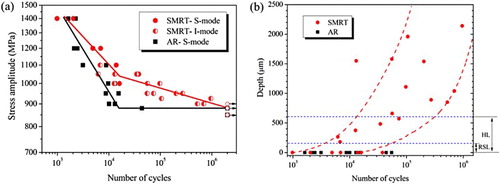
Observations of fracture surfaces showed that the sites of fatigue crack initiation change from predominately at surfaces under stress amplitudes above 1050 MPa to at subsurface (or interior) zones under stress amplitudes below 1050 MPa in the SMRT samples. In comparison, fatigue cracks always initiate at surfaces on the AR samples. As shown in Figure , an internal crack initiates at ∼1.5 mm below the surface and leads to the fracture after ∼2.0 × 10⁵ cycles in the SMRT sample at 950 MPa, while a crack initiates at the surface and leads to the fracture after ∼8.6 × 10³ cycles on the AR sample at the same stress amplitude. Detailed analyses on all fractured samples, combining microstructure and chemical composition observations, revealed that the sites of internal crack initiation are characterized by such defects as coarse grains, inclusions, chemical inhomogeneities, and even micro-cracks, which were also typically observed in bearing steels in previous works [Citation4,Citation17,Citation18,Citation29,Citation30]. Furthermore, the whole region of internal crack initiation and early propagation usually exhibits a pattern of a ‘fish-eye’, inside which a relatively rough region presents around the defect (see Figure (c)). And the size of the fish-eye zone is independent of fatigue lifetime, with a mean diameter of 138 ± 18 µm.
Figure 4. SEM morphologies of fracture surface of (a) the SMRT sample and (b) the AR sample after fatigue tests at a stress amplitude of 950 MPa. (c) and (d) Showing the magnified images of the boxed zones on (a) and (b), respectively. The regions of crack initiation and the fish-eye are marked by I and F, respectively.
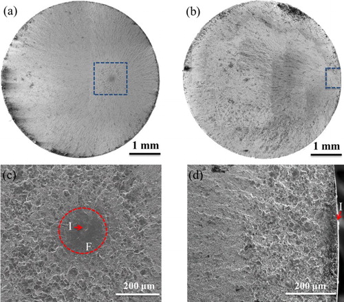
The summarized relationship between the depth of the crack initiation site and the fatigue lifetime (see Figure (b)) indicates that a transition exists in the fatigue mode of the SMRT sample with increasing lifetime: cracks mostly initiate at surface at lifetimes below ∼104 (i.e. in the surface mode), and tend to initiate from the subsurface layer or interior at longer lifetimes (i.e. in the interior mode). Furthermore, the depth value seems to increase with increasing lifetime, and all the cracks initiate at sites deeper than the hardened surface layer at lifetimes above 5 × 10⁴. It is noted that such a transition in fatigue mode and the dependence of fatigue lifetime on crack initiation site might result in the fact that a fatigue limit could not be determined in the SMRT sample.
As the SMRT sample has a comparable surface roughness (Ra within 0.1−0.2 µm) with the AR sample, the effect of surface quality on the fatigue property can be neglected. Therefore, the enhanced fatigue property, mostly related with the suppressed surface-mode failure, is expected to be resulted from the formation of the GNS surface layer and evident surface compressive residual stresses on the SMRT sample, as discussed below.
On the AR sample, surface extrusions and intrusions might form due to slip bands under cyclic loading during a fatigue test [Citation31], and some surface defects (i.e. inclusions and machining flaws) might exist before the test. Therefore, a fatigue failure is expected to initiate from the surface due to a higher initial stress-intensity factor (SIF) range (ΔK). For example, ΔK for a surface defect (ΔKdef,s) and an internal one (ΔKdef,i) can be estimated from
(1)
and
(2)
respectively [Citation16], where σa is the nominal stress amplitude, and
is the size of the defect. For the same defect size, the ΔKdef,s value exceeds the threshold SIF value (ΔKth, ∼4 MPa m1/2 [Citation17]) under a much smaller stress amplitude than the ΔKdef,i value does, leading into the surface-mode failure.
In the GNS surface layer with enhanced hardness and strength, slip bands are suppressed, so that surface extrusions and intrusions are difficult to form on the SMRT sample during fatigue. In addition, cross-sectional SEM observations confirmed that interior inclusions and other defects possibly acting as fatigue crack nuclei are significantly refined and a higher structural homogeneity is obtained in the GNS surface layer. Therefore, a higher stress amplitude is required to enable the surface-mode failure at stress >1050 MPa according to Equation (1). Otherwise, the fatigue failure transforms into the interior mode if the initial SIF around an internal defect reaches the critical value to enable the formation of a fish-eye zone and the crack growth, when the surface-mode failure is suppressed at stress <1050 MPa. And a much higher stress amplitude is required according to Equation (2).
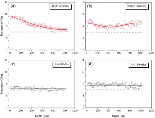
It is noticed that the enhancement in fatigue property becomes smaller at stresses >1050 MPa (see Figure (a)). This is induced by the significant cyclic hardening in the sample interior during fatigue under a higher stress amplitude. As shown in Figure (a), the increment in the matrix hardness of the SMRT sample is only ∼0.2 GPa after the fatigue failure at 950 MPa, and the hardness distribution along depth maintains a similar trend to that of the as-SMRT sample, so that fatigue failure occurs in the interior mode. In comparison, the matrix hardness of the SMRT sample increases from ∼8.5 to ∼9.3 GPa and the hardness difference between the surface and the matrix decreased markedly after the fatigue failure at 1400 MPa (see Figure (b)). In this case, the surface roughening process might become more distinct, so that fatigue failure transforms from interior mode to surface mode. In the AR sample, a comparable hardness of the surface layer and the matrix is kept after fatigue under both the higher and lower stress amplitudes, as shown in Figure (c,d), so that the fatigue failure remains in the surface mode.
Figure 5. In-depth distributions of microhardness in the SMRT sample after fatigue fracture at (a) 950 MPa for ∼2.0 × 10⁵ cycles and (b) 1400 MPa for ∼2.0 × 10³ cycles, and in the AR sample after fatigue fracture at (c) 950 MPa for ∼8.6 × 10³ cycles and (d) 1400 MPa for ∼2.2 × 10³ cycles. The dashed line in each plot shows microhardness distribution in the AR sample for a reference.
In addition, residual stress (σr) acts on the fatigue behavior as a mean stress and affects the crack initiation and propagation in the tension side [Citation16]. And Equation (1) is rewritten as [Citation32]
(3)
That is to say, the initial SIF range of a surface defect will be further decreased by a compressive residual stress. As shown in Figure (b), almost no crack initiated within the surface layer with obvious compressive residual stresses, while some initiated from regions beyond the layer with compressive residual stresses but within the hardened layer in the SMRT sample. This suggests the importance of compressive residual stress on suppressing surface-mode failure.
The compressive residual stress will relax during fatigue cycling under higher stress amplitudes, also contributing to a transition in fatigue mode. As shown in Figure (b), the residual stress at the topmost surface layer of the SMRT sample decreased to ∼230 MPa after fatigue fracture at 1400 MPa. Significant relaxations of compressive residual stress and even conversion to tensile residual stress were observed during fatigue in materials processed by shot peening [Citation16,Citation33]. And the results showed that the relaxation usually reached a saturated level at an earlier stage (∼0.2 of the fatigue life). Therefore, the initial SIF value at the sample surface will be increased according to Equation (3), and a transition in failure mode from the interior to the surface is facilitated in the SMRT sample.
While the compressive residual stress also significantly relaxed under the stress amplitude of 950 MPa, the fatigue fracture still occurred in the interior mode. Considering the evidences that the hardness difference between the surface and the interior remained almost unchanged in the SMRT-950 MPa sample but became much smaller in the SMRT-1400 MPa sample, one may infer a minor importance of the compressive residual stress than of the increased hardness in the GNS layer on suppressing surface fatigue cracking.
Conclusions
In this work, a GNS surface layer has been produced on a quenched and tempered 52100 bearing steel by means of SMRT. The initial microstructure of martensite plates with cementite and retained austenite was transformed into martensite grains with a mean size of ∼24 nm at the top surface layer. The formation mechanism of the GNS layer is predominated by dislocation activities under high strains and strain rates. In comparison with traditional surface treatments (i.e. shot peening and deep rolling), SMRT produced a hardened surface layer with much larger thickness (∼600 µm).
Axial tension–compression fatigue tests showed that an enhanced fatigue property was achieved on the SMRT sample within the conventional low and high cycle fatigue regimes. The fatigue fracture in the mode of surface crack initiation and propagation was suppressed at a critical stress amplitude of ∼1050 MPa, below which a mode of internal crack initiation and propagation dominated the fatigue fracture and led to a much larger fatigue lifetime. The enhanced fatigue property accompanied by the suppressed surface-mode fracture in the SMRT sample might be related to the decreased initial SIF value in the GNS surface layer, mostly due to its higher strength and structural homogeneity. In addition, the remarkable compressive residual stress decreased the SIF value at the surface and also enhanced the fatigue property.
Acknowledgements
The authors are grateful to Profs. S.X. Li and Z.F Zhang for valuable discussion.
Disclosure statement
No potential conflict of interest was reported by the authors.
Additional information
Funding
References
- Schijve J. Fatigue of structures and materials. New York (NY): Springer; 2009.
- Furuya Y, Matsuoka S. Improvement of gigacycle fatigue properties by modified ausforming in 1600 and 2000 MPa-class low-alloy steels. Metall Mater Trans. 2002;33:3421–3431. doi: 10.1007/s11661-002-0329-5
- Zhao A, Xie J, Sun C, et al. Effects of strength level and loading frequency on very-high-cycle fatigue behavior for a bearing steel. Int J Fatigue. 2012;38:46–56. doi: 10.1016/j.ijfatigue.2011.11.014
- Li SX. Effects of inclusions on very high cycle fatigue properties of high strength steels. Int Mater Rev. 2012;57:92–114. doi: 10.1179/1743280411Y.0000000008
- Lu K, Lu J. Surface nanocrystallization (SNC) of metallic materials – presentation of the concept behind a new approach. J Mater Sci Technol. 1999;15:193–201. doi: 10.1179/026708399101505707
- Lu K, Lu J. Nanostructured surface layer on metallic materials induced by surface mechanical attrition treatment. Mater Sci Eng. 2004;375–377:38–45. doi: 10.1016/j.msea.2003.10.261
- Tao NR, Wang ZB, Tong WP, et al. An investigation of surface nanocrystallization mechanism in Fe induced by surface mechanical attrition treatment. Acta Mater. 2002;50:4603–4616. doi: 10.1016/S1359-6454(02)00310-5
- Fang TH, Li WL, Tao NR, et al. Revealing extraordinary intrinsic tensile plasticity in gradient nano-grained copper. Science. 2011;331:1587–1590. doi: 10.1126/science.1200177
- Huang HW, Wang ZB, Lu J, et al. Fatigue behaviors of AISI 316L stainless steel with a gradient nanostructured surface layer. Acta Mater. 2015;87:150–160. doi: 10.1016/j.actamat.2014.12.057
- Yang L, Tao NR, Lu K, et al. Enhanced fatigue resistance of Cu with a gradient nanograined surface layer. Scripta Mater. 2013;68:801–804. doi: 10.1016/j.scriptamat.2013.01.031
- Villegas JC, Shaw LL, Dai K, et al. Enhanced fatigue resistance of a nickel-based Hastelloy induced by a surface nanocrystallization and hardening process. Phil Mag Lett. 2005;85:427–438. doi: 10.1080/09500830500311705
- Roland T, Retraint D, Lu K, et al. Fatigue life improvement through surface nanostructuring of stainless steel by means of surface mechanical attrition treatment. Scripta Mater. 2006;54:1949–1954. doi: 10.1016/j.scriptamat.2006.01.049
- Peterson RE. Stress concentration factors. New York: John Wiley & Sons; 1974.
- Lu LT, Shiozawa K, Jiang Y. Influence of deeply rolling process on ultra-long life fatigue behavior of high carbon-chromium bearing steel. Acta Metall Sin. 2006;42:515–520.
- Shiozawa K, Lu L. Very high-cycle fatigue behaviour of shot-peened high-carbon–chromium bearing steel. Fatigue Fract Eng Mater Struct. 2002;25:813–822. doi: 10.1046/j.1460-2695.2002.00567.x
- Shiozawa K, Murai M, Shimatani Y, et al. Transition of fatigue failure mode of Ni–Cr–Mo low-alloy steel in very high cycle regime. Int J Fatigue. 2010;32:541–550. doi: 10.1016/j.ijfatigue.2009.06.011
- Shiozawa K, Hasegawa T, Kashiwagi Y, et al. Very high cycle fatigue properties of bearing steel under axial loading condition. Int J Fatigue. 2009;31:880–888. doi: 10.1016/j.ijfatigue.2008.11.001
- Bhadeshia HKDH. Steels for bearings. Prog Mater Sci. 2012;57:268–435. doi: 10.1016/j.pmatsci.2011.06.002
- Huang HW, Wang ZB, Yong XP, et al. Enhancing torsion fatigue behaviour of a martensitic stainless steel by generating gradient nanograined layer via surface mechanical grinding treatment. Mater Sci Technol. 2013;29:1200–1205. doi: 10.1179/1743284712Y.0000000192
- Guo YB, Liu GR. Mechanical properties of hardened AISI 52100 steel in hard machining processes. J Manuf Sci Eng. 2002;124:1–9. doi: 10.1115/1.1413775
- Hosseini SB, Klement U, Yao Y, et al. Formation mechanisms of White layers induced by hard turning of AISI 52100 steel. Acta Mater. 2015;89:258–267. doi: 10.1016/j.actamat.2015.01.075
- Wang LM, Wang ZB, Lu K. Grain size effects on the austenitization process in a nanostructured ferritic steel. Acta Mater. 2011;59:3710–3719. doi: 10.1016/j.actamat.2011.03.006
- Zhou L, Liu G, Han Z, et al. Grain size effect on wear resistance of a nanostructured AISI52100 steel. Scripta Mater. 2008;58:445–448. doi: 10.1016/j.scriptamat.2007.10.034
- Li JG, Umemoto M, Todaka Y, et al. A microstructural investigation of the surface of a drilled hole in carbon steels. Acta Mater. 2007;55:1397–1406. doi: 10.1016/j.actamat.2006.09.043
- Mitamura N, Hidaka H, Takaki S. Microstructural development in bearing steel during rolling contact fatigue. Mater Sci Forum. 2007;539–543:4255–4260. doi: 10.4028/www.scientific.net/MSF.539-543.4255
- Zhou L, Liu G, Ma XL, et al. Strain-induced refinement in a steel with spheroidal cementite subjected to surface mechanical attrition treatment. Acta Mater. 2008;56:78–87. doi: 10.1016/j.actamat.2007.09.003
- Stickels CA, Peters CR. Compressive strain-induced austenite transformation in 52100 steel. Metall Mater Trans. 1977;8:1193–1195. doi: 10.1007/BF02667406
- Kong L, Lao Y, Xiong T, et al. Nanocrystalline surface layer on AISI 52100 steel induced by supersonic fine particles bombarding. J Therm Spray Technol. 2013;22:1007–1013. doi: 10.1007/s11666-013-9934-7
- Sakai T, Sato Y, Oguma N. Characteristic S–N properties of high-carbon-chromium-bearing steel under axial loading in long-life fatigue. Fatigue Fract Eng Mater Struct. 2002;25:765–773. doi: 10.1046/j.1460-2695.2002.00574.x
- Li W, Sakai T, Li Q, et al. Effect of loading type on fatigue properties of high strength bearing steel in very high cycle regime. Mater Sci Eng. 2011;528:5044–5052. doi: 10.1016/j.msea.2011.03.020
- Mughrabi H. Specific features and mechanisms of fatigue in the ultrahigh-cycle regime. Int J Fatigue. 2006;28:1501–1508. doi: 10.1016/j.ijfatigue.2005.05.018
- Tanaka K, Akiniwa Y. Fatigue crack propagation behaviour derived from S–N data in very high cycle regime. Fatigue Fract Eng Mater Struct. 2002;25:775–784. doi: 10.1046/j.1460-2695.2002.00547.x
- Dalaei K, Karlsson B, Svensson L-E. Stability of shot peening induced residual stresses and their influence on fatigue lifetime. Mater Sci Eng. 2011;528:1008–1015. doi: 10.1016/j.msea.2010.09.050